Narrow Bandpass Filters (FNP) - Millitech
Narrow Bandpass Filters (FNP) - Millitech
Narrow Bandpass Filters (FNP) - Millitech

Create successful ePaper yourself
Turn your PDF publications into a flip-book with our unique Google optimized e-Paper software.
Millimeter-Wave Technology & Solutions<br />
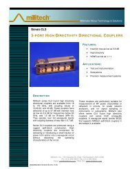
SERIES <strong>FNP</strong><br />
NARROW BANDPASS FILTERS<br />
FEATURES:<br />
<br />
<br />
<br />
Low insertion loss<br />
High selectivity<br />
Custom designed to meet specific<br />
requirements<br />
APPLIC ATIONS:<br />
<br />
<br />
<br />
Pre-selector filter<br />
Spurious mode suppression<br />
Instrumentation<br />
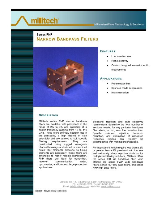
DESCRIPTION<br />
<strong>Millitech</strong> series <strong>FNP</strong> narrow bandpass<br />
filters are available with passbands in the<br />
range of 2% to 4% and operating at a<br />
center frequency ranging from 18 to 110<br />
GHz. These filters offer low insertion loss in<br />
the passband, a high degree of skirt<br />
selectivity and are tailored to suit specific<br />
filtering requirements. They are<br />
constructed using rugged waveguide<br />
channel housings and etched or machined<br />
circuit filter elements. Because no tuning<br />
elements are necessary, these filters are<br />
amenable to highly reliable reproduction.<br />
<strong>FNP</strong> filters are ideal for transmitter,<br />
receiver, communication, radar,<br />
upconverter, and low-cost, large production<br />
applications.<br />
Stopband rejection and skirt selectivity<br />
requirements determine the total number of<br />
sections needed for any particular bandpass<br />
filter which, in turn, sets filter insertion loss.<br />
Specific sideband rejection, harmonic<br />
reduction, and elimination of undesired<br />
frequency regions can typically be<br />
accomplished with minimal insertion loss.<br />
For applications which require less than a 2%<br />
or greater than a 4% passband with low loss<br />
and extremely sharp rejection skirts or for<br />
multiplexed filtering solutions, <strong>Millitech</strong> offers<br />
the series FIB iris bandpass filter. Also<br />
offered are series FWP wide bandpass<br />
filters, series FLP low pass filters, and series<br />
FHP high pass filters.<br />
IS000051 REV03 ECO#1302-06-05<br />
<strong>Millitech</strong>, Inc. • 29 Industrial Dr. East • Northampton, MA 01060<br />
Ph. (413) 582-9620 • Fax (413) 582-9622<br />
Email: info@millitech.com • Web Site: www.millitech.com
ATTENUATION (dB)<br />
Millimeter-Wave Technology & Solutions<br />
Figure 1 - General Characteristics of <strong>Narrow</strong> <strong>Bandpass</strong> Fillers.<br />
0<br />
IL<br />
BW<br />
L RL<br />
L RH<br />
f RL<br />
f RH<br />
1.5BW<br />
1.5BW<br />
Legend<br />
BW = bandwith<br />
F C = center frequency<br />
F RL = (f C – 1.5 BW); low side<br />
rejection frequency<br />
F RH = (f C + 1.5 BW); high side<br />
rejection frequency<br />
L RL = rejection at f RL<br />
L RH = rejection at f RH<br />
f C<br />
FREQUENCY<br />
ELECTRIC AL SPECIFICATIONS<br />
Model Number <strong>FNP</strong>-42 <strong>FNP</strong>-28 <strong>FNP</strong>-22 <strong>FNP</strong>-19 <strong>FNP</strong>-15 <strong>FNP</strong>-12 <strong>FNP</strong>-10 <strong>FNP</strong>-08<br />
Insertion Loss (dB) (max) *1 2% 1.8 1.8 1.8 1.8 2.0 2.0 2.2 *3<br />
4% 1.6 1.6 1.6 1.6 1.6 1.8 2.0 *3<br />
Low side rejection level (dB)<br />
2<br />
at F RL (min)*<br />
40 40 40 40 40 40 40 *3<br />
High side rejection level (dB)<br />
2<br />
at F RH (min)*<br />
30 30 30 30 30 30 30 *3<br />
Passband VSWR (typ) 1.5:1 1.5:1 1.5:1 1.5:1 1.5:1 1.5:1 1.5:1 *3<br />
*1 – Data is based upon a 5-section filter. Upper limit is ~6% bandwidth and 8 sections.<br />
*2 – Standard rejection frequencies (F RL and F RH ) are calculated at center frequency ± (1.5 x bandwidth in GHz).<br />
*3 – Please consult <strong>Millitech</strong> for further information.<br />
NOTE: Other bandwidth percentages are available upon request. See series FIB for other bandwidth<br />
requirements and options, or contact <strong>Millitech</strong> for more information.<br />
IS000051 REV03 ECO#1302-06-05<br />
<strong>Millitech</strong>, Inc. • 29 Industrial Dr. East • Northampton, MA 01060<br />
Ph. (413) 582-9620 • Fax (413) 582-9622<br />
Email: info@millitech.com • Web Site: www.millitech.com
Millimeter-Wave Technology & Solutions<br />
OUTLINE DR AWINGS*<br />
*The outlines shown may not reflect the latest information. Please contact <strong>Millitech</strong> for current outline drawings.<br />
MECHANICAL SPECIFICATIONS<br />
Model Number <strong>FNP</strong>-42 <strong>FNP</strong>-28 <strong>FNP</strong>-22 <strong>FNP</strong>-19 <strong>FNP</strong>-15 <strong>FNP</strong>-12 <strong>FNP</strong>-10 <strong>FNP</strong>-08<br />
A (in/mm) 0.88/22.4 0.75/19.1 1.13/28.7 1.13/28.7 0.75/19.1 0.75/19.1 0.75/19.1 0.75/19.1<br />
B (in/mm) *1 *1 *1 *1 *1 *1 *1 *1<br />
Flange MIL.F-3922 /54-001 *2 /54-003 *2 /67B-006 /67B-007 /67B-008 /67B-009 /67B-010 /67B-M08<br />
*1 - Dimensions vary depending upon filter requirements. Please contact <strong>Millitech</strong> for more information.<br />
*2 – With #4-40 threaded holes.<br />
HOW TO ORDER<br />
Specify Model Number* 1<br />
<strong>FNP</strong>-XX-AABØC<br />
XX = Waveguide Band<br />
WR – number<br />
AA = Bandwidth* 2<br />
Example:<br />
03 - 3% bandwidth<br />
B = Flange Type<br />
R – round (WR-28 through WR-08 only)<br />
S – square (WR-42 through WR-22 only)<br />
C = Other Options<br />
N – nonstandard (specify requirements)<br />
Ø – standard rejection levels<br />
*1 – Please specify center frequency when ordering.<br />
*2 – Bandwidth expressed as a percentage of center frequency - 12% maximum.<br />
IS000051 REV03 ECO#1302-06-05<br />
<strong>Millitech</strong>, Inc. • 29 Industrial Dr. East • Northampton, MA 01060<br />
Ph. (413) 582-9620 • Fax (413) 582-9622<br />
Email: info@millitech.com • Web Site: www.millitech.com