Download Millitech's Standard Products Catalog in Adobe .pdf format
Download Millitech's Standard Products Catalog in Adobe .pdf format
Download Millitech's Standard Products Catalog in Adobe .pdf format

You also want an ePaper? Increase the reach of your titles
YUMPU automatically turns print PDFs into web optimized ePapers that Google loves.
Millimeter-Wave Technology & DesignJune 2013MISSION STATEMENTABOUT MILLITECHTo establish Millitech as the leader <strong>in</strong> our<strong>in</strong>dustry by committ<strong>in</strong>g ourselves to thesuccess of our customers, team members,and other bus<strong>in</strong>ess associates through acont<strong>in</strong>uous focus on <strong>in</strong>tegrity and excellence<strong>in</strong> everyth<strong>in</strong>g we do.Millitech specializes <strong>in</strong> the design, eng<strong>in</strong>eer<strong>in</strong>g andmanufactur<strong>in</strong>g of components, assemblies,subsystems and fully <strong>in</strong>tegrated systems forapplications <strong>in</strong> satellite communications, radiometry,radar and remote sens<strong>in</strong>g. Our broad productportfolio, <strong>in</strong> conjunction with the wide range oftechnologies and markets served, enables thecompany to monitor emerg<strong>in</strong>g applications, quicklydevelop prototypes, and create high qualitymillimeter-wave products and technologies for thespace, military and commercial fields.We are dedicated to help<strong>in</strong>g our customersachieve their quality, performance and cost objectives.For over three decades, our Millimeter-Wave<strong>Products</strong> Division has had a reputation for provid<strong>in</strong>gthe highest quality millimeter-wave products <strong>in</strong>the world. We offer the broadest selection of standardmillimeter-wave components and assemblies<strong>in</strong> the 18 to 325 GHz range. In addition, <strong>Millitech's</strong>extensive experience <strong>in</strong> advanced products andsystem design results <strong>in</strong> expertise <strong>in</strong> all millimeterwaveapplications and products.Millitech uses state-of-the-art software such asHFSS, ADS, GRASP and SolidWorks Simulationplus many other model<strong>in</strong>g programs for antennasand Gaussian optics to enable the design ofanyth<strong>in</strong>g from m<strong>in</strong>iaturized <strong>in</strong>tegrated hybridassemblies to complete subsystems. Depend<strong>in</strong>gon customer requirements, we are able to achievequick turnaround time and smooth transitions tovolume manufactur<strong>in</strong>g for most designs.For over ten years, our Manufactur<strong>in</strong>g ServicesDivision has been provid<strong>in</strong>g contract manufactur<strong>in</strong>gand test services for antennas, antenna pedestalsystems, radars and other high frequency systemsfor both military and commercial customers. Hav<strong>in</strong>gsupplied thousands of high frequency subsystems tomilitary, space and commercial programs, Millitechhas established itself as an award-w<strong>in</strong>n<strong>in</strong>gmanufactur<strong>in</strong>g partner.QUALITY STANDARDSMillitech’s Quality Management System is registeredto AS9100, ISO 9001, OHSAS 18001, and ISO14001 standards that are <strong>in</strong>corporated <strong>in</strong>to all of ourbus<strong>in</strong>ess processes. The <strong>in</strong>tegration of the Sales,Eng<strong>in</strong>eer<strong>in</strong>g, Procurement and Manufactur<strong>in</strong>gDepartments <strong>in</strong>to our Quality System ensuresproduct <strong>in</strong>tegrity from <strong>in</strong>itial receipt of an <strong>in</strong>quirythrough design and manufactur<strong>in</strong>g.PRODUCT/SPECIFICATION CHANGESThe <strong>in</strong><strong>format</strong>ion <strong>in</strong> this catalog is current at the timeof release. However, Millitech reserves the right tomake changes without notice. Please consult ourwebsite for the most current <strong>in</strong><strong>format</strong>ion.(www.millitech.com)1Millitech, Inc. •Tel: (413) 582-9620 • Fax: (413) 582-9622 • Email: <strong>in</strong>fo@millitech.com
TitleMillimeter-Wave Technology & DesignTable of ContentsAdvanced <strong>Products</strong> 3Applications Experience 4AEHF and WGS Frequency Conversion Systems 5Advanced Antenna <strong>Products</strong> 6Manufactur<strong>in</strong>g Services Division (MSD) 8Antenna and Quasioptical <strong>Products</strong> 9(SFH) Scalar Feed Horn(CRA) Cassegra<strong>in</strong> Reflector Antenna(GOA) Gaussian Optics Antenna(GFS) Freestand<strong>in</strong>g Wire Grid Polarizer(OMT) Orthomode Transducer(POL) L<strong>in</strong>earCircular Polarizer(WAC) Circular-Rectangular Waveguide Adapter (WRJ) Rotary Jo<strong>in</strong>t(SGH) <strong>Standard</strong> Ga<strong>in</strong> Horn(MPC) Monopulse ComparatorMixers and Detectors 14(MXP) Balanced Mixer(MB1) Biasable Balanced Mixer(DET) General Purpose Detector(MSH) Subharmonic Mixer(MHP) General Purpose Harmonic Mixer(MUP) Upconverter(MIQ) I/Q MixerMultiplier <strong>Products</strong> 19(MUD) Fullband Frequency Doubler(MUT) Fullband Frequency Tripler(AMC) Active Multiplier Cha<strong>in</strong>Amplifier and Oscillators 24(GDM) Mechanically-Tuned Gunn Oscillator (GDV) Voltage-Controlled Gunn Oscillator(LNA) Low Noise Amplifier(AMP) Power AmplifierControl Components 27(PSP) SPST PIN Switch(PSH) High Speed SPST PIN Switch(PDT) SPDT PIN Switch(PS3) SP3T PIN Switch(VCA) Voltage-Controlled Variable AttenuatorFerrite and Filter <strong>Products</strong> 30(FBI) Fullband Isolator(JFD) Ferrite Isolator and Circulator(WBI) Wide Band Isolator(FLP) Low Pass Filter(FIB) Iris Bandpass Filter(FNP) Narrow Bandpass Filter(FHP) High Pass Filter(HPC) High Power CirculatorPassive Waveguide <strong>Products</strong> 35(CGC) Crossguide Coupler(CL3) 3-Port High Directivity Directional Coupler(CMT) Magic Tee Hybrid Coupler(CSS) Short Slot Hybrid Coupler(FXA) Gen. Purpose & Precision Fixed Attenuator (LSA) Level Set Attenuator(VPS) Variable Phase Shifter(WTR) Term<strong>in</strong>ation(TLD) Tunable Load(TSC) Tunable Short(WCA) Waveguide to Coax AdapterTest and Measurement <strong>Products</strong> 40(DRA) Direct Read<strong>in</strong>g Attenuator, Precision (MWA) Motorized Waveguide Attenuator<strong>Standard</strong> Circular Waveguide Sizes Table 42<strong>Standard</strong> Rectangular Waveguide Specification & MIL Specification Cross Reference 43Antenna and Quasioptical Product Capability Plots 44Page2Millitech, Inc. •Tel: (413) 582-9620 • Fax: (413) 582-9622 • Email: <strong>in</strong>fo@millitech.com
Millimeter-Wave Technology & DesignAdvanced <strong>Products</strong>Millitech has over 25 years experience <strong>in</strong> provid<strong>in</strong>g a wide range of technical solutions meet<strong>in</strong>g specializedrequirements. We work closely with customers from concept development through production. <strong>Millitech's</strong> advancedproduct capabilities <strong>in</strong>clude modifications to our standard catalog component designs, fabrication andcharacterization of specialized components, <strong>in</strong>tegration of multifunctional modules, and the design and <strong>in</strong>tegration ofturn-key systems such as radars, <strong>in</strong>terferometers, radiometers and reflectometers.Major Customers and ProjectsBall Aerospace / NASA GSFC / SAOSWAS (Sub – Millimeter-Wave AstronomySatellite) Space Qualified 490/550 GHzRadiometer SystemGMI 89, 166, 183 GHz ReceiversAlenia SpazioContraves Space Qualified Ka-Band MultiplierJPL Space Qualified K- & Ka-Band MixersHIFI, Space Qualified W-Band IsolatorsNorthrop Grumman Space TechnologyAEHF, Space Qualified 60 GHz PowerComb<strong>in</strong>ers and other waveguide componentsNorthrop Grumman Electronic SystemsSSMIS, Space Qualified V- & W-Band MixersAMSU-A, Space Qualified Gunn OscillatorATMS, Space Qualified V- & W-BandBoe<strong>in</strong>g Space and Intelligence SystemsCMIS, Space Qualified 166/183 GHzFront-End FAB-T, RF Converter ModulesMitsubishi Electronic Corporation (MELCO)Space Qualified W-Band Local OscillatorQ<strong>in</strong>etiQTarsier Radar W-Band Front EndCaterpillarW-Band Scann<strong>in</strong>g Radar SystemLockheed Mart<strong>in</strong> Commercial Space SystemsSpace Qualified V-Band Power Comb<strong>in</strong>ersViaSatGapfiller Gateway ConvertersNaval Research LabMIS 54, 89, 166, 183 GHz ReceiversMMW SubSystems ExperienceMMW Po<strong>in</strong>t-to-Po<strong>in</strong>tRadiosMMW WidebandDownconverterSubSystemsPo<strong>in</strong>t-to-Po<strong>in</strong>t RadioMonopulse/Track<strong>in</strong>g RadarCoherent Pulsed RadarFMCW RadarInterferometersReflectometersW-Band FOD RadarLevel Sens<strong>in</strong>g RadarPerimeter DetectionFOD DetectionSignal IntelligenceTest and MeasurementV-Band and E-BandMeasurementPlasma Imag<strong>in</strong>g3Millitech, Inc. •Tel: (413) 582-9620 • Fax: (413) 582-9622 • Email: <strong>in</strong>fo@millitech.com
Applications ExperienceMillimeter-Wave Technology & DesignRadar - Millitech has over 20 years experience develop<strong>in</strong>g radars fornumerous applications cover<strong>in</strong>g a frequency range from 18 to 140 GHz.We developed the first commercial vehicle radar at 77 GHz for Daimler-Benz <strong>in</strong> 1996, and have the experience and flexibility to developsolutions for challeng<strong>in</strong>g sens<strong>in</strong>g applications, especially where size andresolution are critical. Our frequency multiplier technology is ideallysuited for coherent radar applications <strong>in</strong>clud<strong>in</strong>g frequency-agile andFMCW radar. Millitech also has the requisite expertise and high powerMMW circulators to <strong>in</strong>tegrate TWTA’s or other high power devices <strong>in</strong>tocurrent or custom designed radar systems. Please consult Millitech formore <strong>in</strong><strong>format</strong>ion on our radar capabilities or to discuss specificrequirements.Power Dividers/Comb<strong>in</strong>ers and SSPAs - Millitech has developed anumber of solutions for highly efficient millimeter-wave power divid<strong>in</strong>gand comb<strong>in</strong><strong>in</strong>g. These units are ideal for low-loss isolated powercomb<strong>in</strong><strong>in</strong>g for commercial, military and satellite applications. Theselow-loss comb<strong>in</strong>ers are used <strong>in</strong> our Solid State Power Amplifiers(SSPAs). Millitech utilizes both electroform<strong>in</strong>g and CNC mach<strong>in</strong><strong>in</strong>gtechniques to achieve low <strong>in</strong>sertion loss, high po<strong>in</strong>t-to-po<strong>in</strong>t isolation,and excellent phase balance. Millitech also offers a number of theseunits as standard products and can accommodate a wide variety ofcomb<strong>in</strong><strong>in</strong>g requirements.Multi-Component Assemblies - From rapid prototyp<strong>in</strong>g tothe qualification of <strong>in</strong>tegrated or discrete componentdesign, Millitech has extensive capabilities <strong>in</strong> the area ofsubsystem design and test. In addition to measur<strong>in</strong>g theperformance characteristics and test parameters requiredfor our standard millimeter-wave products and subsystems,the performance of high reliability <strong>in</strong>tegrated hardware canbe fully characterized. To support millimeter-wave systemsfor specific commercial, space or military applications,Millitech has the facilities and necessary equipment topermit real life test <strong>in</strong> true application scenarios. Fieldtest<strong>in</strong>g and on-site verification of millimeter-wave systemsis one of <strong>Millitech's</strong> unique capabilities.4Millitech, Inc. •Tel: (413) 582-9620 • Fax: (413) 582-9622 • Email: <strong>in</strong>fo@millitech.com
Millimeter-Wave Technology & Design20, 30 and 45 GHz AEHF and WGSFrequency Conversion SystemsAEHF / WGS UpconverterInternal viewInstalled WGSConverter SystemAEHF / WGS / GBSDownconverter, Internal viewMillitech is at the forefront <strong>in</strong> the production of conversion systems for the next generation of militarysatellites. Millitech has been awarded contracts, and is currently produc<strong>in</strong>g systems for both the AEHF andWGS satellites. These major converter awards cover Army, Navy and Air Force specifications and meet allof the strict RF and environmental requirements. The systems are modular and span the completeupconversion cha<strong>in</strong> to Q- and Ka-Band and downconversion cha<strong>in</strong> from K-Band. The systems <strong>in</strong>cludeprecise level control to and from an external modem.At a time when many potential satellite users are merely def<strong>in</strong><strong>in</strong>g system requirements, Millitech hasalready produced the conversion systems required for these applications. These exist<strong>in</strong>g designs caneasily be modified for custom applications. Our converters benefit from Millitech’s experience andreputation for quality <strong>in</strong> the Military SATCOM <strong>in</strong>dustry. Utilization of Millitech converters will result <strong>in</strong> costand schedule sav<strong>in</strong>gs, and can substantially reduce technical risk on any new satellite, ground, mobile orairborne system.Receiver IF Control ModuleTransmit IF Control Module5Millitech, Inc. •Tel: (413) 582-9620 • Fax: (413) 582-9622 • Email: <strong>in</strong>fo@millitech.com
Millimeter-Wave Technology & DesignAdvanced Antenna <strong>Products</strong>Millitech is a lead<strong>in</strong>g supplier of millimeter-wave antennas and associated products for frequencies rang<strong>in</strong>g from 7 to325 GHz and beyond. The Millitech design team <strong>in</strong>cludes experienced millimeter-wave antenna and mechanicaleng<strong>in</strong>eers who provide custom designed antenna and radome solutions for specific applications. These antennascan be <strong>in</strong>tegrated with millimeter-wave component assemblies to provide the highest level of <strong>in</strong>tegration. Below area few of our supported technology areas and application specific product examples. Please contact our salesdepartment to discuss your specific needs.ArraysMillitech has developed designs for array antennas that are be<strong>in</strong>g used for satellite, radar and LOScommunications. Our experience <strong>in</strong>cludes a Ka-Band multi-use, multipolarization phased array for radar andcommunication.The major advantage of quasioptics is low loss,particularly at near millimeter and submillimeterwavelengths. The actual loss <strong>in</strong> propagationbetween focus<strong>in</strong>g elements can be made arbitrarilysmall by proper system design. The reflection lossfrom metal mirrors is virtually immeasurablethroughout the millimeter region, while the loss fromproperly designed lenses is only a few percent.Another important advantage of free spacetransmission versus waveguide is the ability tosupport all polarizations. Very high isolation (on theorder of 40 dB) can be ma<strong>in</strong>ta<strong>in</strong>ed betweenorthogonal polarizations. Gaussian optics can alsosupport more than one spatial mode, which isuseful for both imag<strong>in</strong>g and monopulse feedsystems.Gaussian OpticsMillitech has a history of over 25 years <strong>in</strong> design<strong>in</strong>g high performance Gaussian optic, or quasioptic antennasystems. Applications <strong>in</strong>clude radar, surveillance, remote sens<strong>in</strong>g, material studies, avionics, radio astronomy andplasma diagnostics.6Millitech, Inc. •Tel: (413) 582-9620 • Fax: (413) 582-9622 • Email: <strong>in</strong>fo@millitech.com
Millimeter-Wave Technology & DesignMonopulse AntennasMillitech has developed monopulse antennas with waveguide feeds and dual polarization monopulse antennas forlenses and reflectors. The most important attributes of these antennas are their compact size and low loss. Thefigure below shows a 4” dual polarization, dual channel (AZ/EL) Gaussian Optical Antenna monopulse for Ka-Band.Multiband Antenna FeedsMillitech has designed dual polarization multiband feeds for satellite communications (SATCOM) antennas. Thesefeeds reduce the mechanical complexity for new generation SATCOM antennas while <strong>in</strong>creas<strong>in</strong>g thecommunications capacity of exist<strong>in</strong>g SATCOM antennas. Mobile “on the move” applications have size and weightlimitations. These feeds enable s<strong>in</strong>gle aperture mobile coverage.Antenna Test<strong>in</strong>gMillitech has an <strong>in</strong>door Compact Antenna Test Range for test<strong>in</strong>gantennas from 2 <strong>in</strong>ches to 10 feet <strong>in</strong> diameter. The compact antenna isoptically focused to produce accurate far field simulation from 7 GHzthrough 220 GHz. Our positioner can handle any load up to 1000 lbs.and our test capability runs 24/7, <strong>in</strong> a climate controlled environment.<strong>Millitech's</strong> capabilities measur<strong>in</strong>g high ga<strong>in</strong> millimeter wave antennasare unsurpassed with our Near-field Range (NFR). We are currentlyequipped with a Nearfield Systems 5' x 5' planar Near-field AntennaRange with a granite base for added stability. Our Near-field Rangeallows us to test <strong>in</strong> an <strong>in</strong>door controlled sett<strong>in</strong>g and measure large highga<strong>in</strong> antennas with sidelobes <strong>in</strong> some cases 50 dB below the peak,and beam po<strong>in</strong>t<strong>in</strong>g to the 1/100th of a degree. We can coverfrequencies from 8GHz to 225GHz us<strong>in</strong>g phase coherent Millitechfrequency extenders.7Millitech, Inc. •Tel: (413) 582-9620 • Fax: (413) 582-9622 • Email: <strong>in</strong>fo@millitech.com
Millimeter-Wave Technology & DesignManufactur<strong>in</strong>g Services Division (MSD)The Millitech Manufactur<strong>in</strong>g Services Division specializes <strong>in</strong> contract manufactur<strong>in</strong>gof complex and high value-added assemblies for both military and commercialmarkets. MSD operates out of two manufactur<strong>in</strong>g facilities total<strong>in</strong>g over 36,000square feet of production space located <strong>in</strong> South Deerfield, MA. Millitech’s MSDteam has considerable experience manufactur<strong>in</strong>g two and three axis positionersand antenna assemblies for the satellite communications market, radars and highfrequency sens<strong>in</strong>g systems.MSD manufactures, <strong>in</strong>tegrates and characterizes antennas, antenna pedestals andantenna pedestal systems, radars and other high frequency systems for bothmilitary and commercial applications. The MSD team has experience with antennasizes rang<strong>in</strong>g from two <strong>in</strong>ches to over ten feet <strong>in</strong> diameter. Millitech has a longheritage <strong>in</strong> the design, development and production of highly reliable complex X-,Ku-, K, Ka- and Q-Band antenna assemblies for a wide range of applications<strong>in</strong>clud<strong>in</strong>g satellite communications, radar systems, surveillance and air trafficcontrol equipment. Millitech has manufactured the vast majority of the EHFantenna pedestal assemblies presently deployed by the US Navy.The MSD team utilizes an <strong>in</strong>door Compact Antenna Test Range (CATR) with a six footquiet zone that is ideal for the characterization of a wide array of microwave andmillimeter-wave antennas. The range is housed <strong>in</strong> an absorber l<strong>in</strong>ed room that has beenoptimized for high microwave and millimeter-wave frequencies. The large test zone (quietzone) allows for characterization of antenna systems <strong>in</strong> the 7 to 220 GHz frequencyrange with aperture size rang<strong>in</strong>g from 2” to 10 feet <strong>in</strong> diameter and can handleassemblies weigh<strong>in</strong>g up to 455 kilograms (1000 pounds). The CATR also provides aclimate controlled environment to ensure optimum performance and allows for test<strong>in</strong>gregardless of unpredictable weather. It is one of the few compact ranges <strong>in</strong> the world withthe capability to test at very high millimeter-wave frequencies.In addition to the CATR, the facilities conta<strong>in</strong> production space specially suitedfor mechanical, electromechanical and RF antenna system subassembly work.All MSD RF subassemblies <strong>in</strong>clud<strong>in</strong>g feeds, waveguide assemblies and signalpolarizers are fabricated, tuned and tested <strong>in</strong> these labs by highly skilledelectromagnetic and mechanical technicians. Millitech also has clean roomfaciltities available for contam<strong>in</strong>ation sensitive assemblies such as submar<strong>in</strong>esystems and bear<strong>in</strong>g subassemblies. The <strong>in</strong>tegration area <strong>in</strong>cludes a 14-foothigh bay outfitted with an overhead crane system for the assembly of largecast<strong>in</strong>gs and weldments that are typically used <strong>in</strong> pedestal configurations andother large positioner applications. Millitech provides environmental stressscreen<strong>in</strong>g services through the use of four on-site thermal chambers and shakertables.For over 25 years, Millitech has participated <strong>in</strong> numerous military and commercial programs and has supplied thousandsof antennas and antenna systems for use <strong>in</strong> applications rang<strong>in</strong>g from off-the-shelf communications systems to fullyoutfitted military satellite communications term<strong>in</strong>als. MSD is the leader <strong>in</strong> the assembly and test of superior quality, costeffective microwave and millimeter-wave satellite communications antenna systems. Start<strong>in</strong>g with the development andprototype phase, to multiyear production <strong>in</strong>clud<strong>in</strong>g depot and repair work, Millitech has proven itself as a dedicatedpartner, ensur<strong>in</strong>g the success of the product throughout its lifecycle.Our capabilities extend beyond satellite communications to other demand<strong>in</strong>g electromechanical build-to-pr<strong>in</strong>t productionprograms. Millitech’s MSD team has the manufactur<strong>in</strong>g discipl<strong>in</strong>e, quality management program, materials managementand overall system controls to ensure success <strong>in</strong> the most challeng<strong>in</strong>g applications.8Millitech, Inc. •Tel: (413) 582-9620 • Fax: (413) 582-9622 • Email: <strong>in</strong>fo@millitech.com
Millimeter-Wave Technology & DesignAntenna and Quasioptical <strong>Products</strong>MODEL PRODUCT NAME PERFORMANCE/CAPABILITY SUMMARYSFH Scalar Feed Horn The series SFH is a conical horn antenna with corrugation on the <strong>in</strong>side walls.This feature provides symmetrical radiation patterns <strong>in</strong> E- and H-planes. Thisantenna also provides lower sidelobes as compared to the series CHA, conicalhorn antenna. The standard design has a 3 dB beamwidth of 25° (typical) from18 to 220 GHz. The series SFH is offered with circular or rectangularwaveguide output. The circular waveguide output version can support multiplepolarization and be used <strong>in</strong> conjunction with other Millitech products such asthe POL, SPL and WAC series.CRA Cassegra<strong>in</strong> Reflector Antenna The series CRA Cassegra<strong>in</strong> reflector antennas are available for operation over18 to 325 GHz with standard reflector diameters rang<strong>in</strong>g from 6”/15.24 cm to48"/121.92 cm, depend<strong>in</strong>g on the frequency. The ma<strong>in</strong> reflector has a highlyaccurate metalized surface and is constructed of either carbon fiber sk<strong>in</strong> withhoneycomb core or mach<strong>in</strong>ed alum<strong>in</strong>um. The sub-reflector is a mach<strong>in</strong>edalum<strong>in</strong>um hyperboloid which is rigidly supported by struts. These struts aredesigned to have m<strong>in</strong>imal cross-section with reduced aperture blockage, andhence, produce low sidelobe levels (typically 18 dB).GOA Gaussian Optics Antenna The series GOA is a Gaussian optics lens antenna that provides high efficiencyand low sidelobes. It offers symmetric antenna patterns <strong>in</strong> E- and H-planes.The antenna is available <strong>in</strong> frequencies rang<strong>in</strong>g from 18 to 220 GHz. The ga<strong>in</strong>and 3 dB beamwidth depend on the aperture size of the lens and thefrequency. The antenna can be configured <strong>in</strong> a number of ways to offerpolarization diversity.GFS Freestand<strong>in</strong>g Wire Grid Polarizer The series GFS freestand<strong>in</strong>g wire grid polarizer consists of an array of parallelwires stretched tightly <strong>in</strong>to a planar surface and affixed to a mount<strong>in</strong>g frame.The closely spaced wires reflect essentially 100% of the electric fieldcomponents parallel to the direction of the wires and transmit the component ofthe field perpendicular to the wires.OMT Orthomode Transducer The series OMT orthomode transducer is used to comb<strong>in</strong>e or separate twoorthogonal l<strong>in</strong>early polarized signals simultaneously. Typically, the output (or<strong>in</strong>put) port is <strong>in</strong> the circular waveguide, which can support l<strong>in</strong>ear polarization.Isolation is greater than 25 dB between the two l<strong>in</strong>ear polarizations, and narrowerband versions with greater isolation are also available. This transducercan be used <strong>in</strong> conjunction with the series POL polarizer to handle circularpolarized signals.POL L<strong>in</strong>ear-to-Circular Polarizer The series POL l<strong>in</strong>ear-circular polarizer converts a polarized signal from l<strong>in</strong>earto circular, or the reverse. The frequency range is 10% maximum of centerfrequency, with a low axial ratio of 1 dB. The series POL l<strong>in</strong>ear-circularWACCircular-to-RectangularWaveguide Adapterpolarizer offers low <strong>in</strong>sertion loss with broadband operation.The series WAC circular-to-rectangular waveguide adapter provides transitionfrom standard rectangular to circular waveguide. The adapter can be used withconical and scalar feed horns, and provides wide bandwidths with low loss andlow VSWR. The series WAC adapter is available <strong>in</strong> a complete range of flangepatterns.WRJ Rotary Jo<strong>in</strong>t The series WRJ rotary jo<strong>in</strong>t allows the transmission of RF signals fromstationary to 360˚ rotat<strong>in</strong>g rectangular waveguide. Common applications<strong>in</strong>clude scann<strong>in</strong>g antennas of any k<strong>in</strong>d used <strong>in</strong> radar and radiometer systems.SGH <strong>Standard</strong> Ga<strong>in</strong> Horn The series SGH standard ga<strong>in</strong> horns, offered as conical and pyramidal, areused to measure ga<strong>in</strong> of other antennas. These horns are offered from 18 to325 GHz <strong>in</strong> twelve waveguide bands. The SGH horns are ideally suited forreference sources <strong>in</strong> dual channel antenna test receivers, and can be used aspickup horns for radiation monitor<strong>in</strong>g.MPC Monopulse Comparator The series MPC monopulse comparator features unrivaled <strong>in</strong>sertion lossperformance far superior to typical <strong>in</strong>dustry counterparts. The comparator is a5-port device that can be used <strong>in</strong> target acquisition and track<strong>in</strong>g systems.9Millitech, Inc. •Tel: (413) 582-9620 • Fax: (413) 582-9622 • Email: <strong>in</strong>fo@millitech.com
Millimeter-Wave Technology & Design(SFH) Scalar Feed HornElectrical SpecificationsPerformance ParameterFrequency rangeBeam angles, HPBWGa<strong>in</strong>SidelobesVSWRCross polarization isolationSFH Range Available18 to 220 GHz 25° dB (nom)5 to 23 dBi (nom)-30 dB (typ)1.5:1 (typ)>30 dB For other frequencies, please consult Millitech. 10 to 60 possible, 25 standard. 5 to 23 dBi standard, depend<strong>in</strong>g on beam angle.For more product <strong>in</strong><strong>format</strong>ion search series SFH at www.millitech.com(CRA) Cassegra<strong>in</strong> Reflector AntennaElectrical SpecificationsPerformanceParameterFrequency Range(GHz)<strong>Standard</strong> ReflectorDiameters (<strong>in</strong>)*Beamwidth (degrees)(nom)RangeAvailable18 to 3256, 10, 12, 18, 24,36, 480.1 to 3.0RemarksPractical range forwaveguide feeds.Other diameters available ascustom products.Beamwidth depends onfrequency and diameterselected.Ga<strong>in</strong> (dBi) (nom) 35 to 60Sidelobes (dB) (typ) 18Depend<strong>in</strong>g on the frequencyand diameter selected.Typical value for standardproduct. Blockage bysubreflector determ<strong>in</strong>essidelobe level.VSWR (typ) 1.5:1Note: Larger, non-standard reflector diameters are available. Please consultMillitech for details.For more product <strong>in</strong><strong>format</strong>ion search series CRA at www.millitech.com10Millitech, Inc. •Tel: (413) 582-9620 • Fax: (413) 582-9622 • Email: <strong>in</strong>fo@millitech.com
Millimeter-Wave Technology & Design(GOA) Gaussian Optics AntennaPerformanceParameterFrequency rangeLens diametersBeam anglesGa<strong>in</strong>RangeAvailable18 to 220 GHz 3 <strong>in</strong> / 7.62 cm6 <strong>in</strong> / 15.24 cm9 <strong>in</strong> / 22.86 cm12 <strong>in</strong> / 30.48 cm0.1 to 10° (typ)25.0 to 53.9 dBi(typ)RemarksPractical range for waveguidefeeds.Other diameters available ascustom products.Depend<strong>in</strong>g on lens diameterselected and frequency ofoperation.Depend<strong>in</strong>g on lens diameterselected and frequency ofoperation.Sidelobes23 dB (typ)Depend<strong>in</strong>g on lens size andrequirements.VSWR 1.5:1 (typ) Return loss 14 dB (typ)Cross polarizationisolation, (dualpolarizationversion)Electrical Specifications>30 dBScalar feed with polarizer gridprovides very high crosspolarization isolation Other ranges available upon request. Please consult Millitech.For more product <strong>in</strong><strong>format</strong>ion search series GOA at www.millitech.com(GFS) Freestand<strong>in</strong>g Wire Grid PolarizerTheoretical Grid Performance (max grid size 10”)Electrical SpecificationsWirediameter(<strong>in</strong>/μm)Wiresper<strong>in</strong>chMaximumoperation (GHz)Typical power transmission atmaximum frequencyE Fieldperpendicular towiresE Fieldparallel towires0.002 / 50 200 220 >0.99
Performance ParameterFrequency rangeSpecification18 to 100 GHz Bandwidth ----Isolation VSWR (OMT) Orthomode TransducerPower handl<strong>in</strong>gElectrical Specifications25 to 40 dB1.4:1 (typ)100 Watts, CW Higher frequencies quoted upon request. Please contact Millitech to discuss bandwidth options. Depend<strong>in</strong>g on requirements. Lower VSWR options may be available depend<strong>in</strong>g onMillimeter-Wave Technology & DesignFor more product <strong>in</strong><strong>format</strong>ion, search series OMT at www.millitech.com(POL) L<strong>in</strong>ear-to-Circular Polarizer(WAC) Circular - to - Rectangular Waveguide AdapterPerformance ParameterElectrical SpecificationsL<strong>in</strong>ear-CircularPolarizerCircular-to-RectangularWaveguide AdapterFrequency range (GHz) 18 to 170 18 to 170Axial ratio, 10% bandwidth(max)1.0 dB ---Cross polarization isolation (dB)(typ)--- >25VSWR (typ) 1.3:1 1.15:1For more product <strong>in</strong><strong>format</strong>ion, search series POL or WAC at www.millitech.com(WRJ) Rotary Jo<strong>in</strong>tElectrical SpecificationsPerformanceUnitsWRJ-10 WRJ-12 WRJ-15Frequency Range 79 – 105 60 – 90 50 – 75 GHzInsertion Loss (typ) 1.1 1.0 1.0 dBInput VSWR (typ) 1.8:1 1.5:1 1.5:1Output VSWR (typ) 1.8:1 1.5:1 1.5:1Max Power (Watts, CW) 290 950 1400 WFor more product <strong>in</strong><strong>format</strong>ion, search series WRJ at www.millitech.com12Millitech, Inc. •Tel: (413) 582-9620 • Fax: (413) 582-9622 • Email: <strong>in</strong>fo@millitech.com
(SGH) <strong>Standard</strong> Ga<strong>in</strong> HornMillimeter-Wave Technology & DesignModel NumberFrequency bandand range (GHz)Electrical SpecificationsPyramidal HornsSGH-42 SGH-28 SGH-22 SGH-19 SGH-15 SGH-12 SGH-10 SGH-08 SGH-06 SGH-05 SGH-04 SGH-03K Ka Q U V E W F D G - -18-26.5 26.5-40 33-50 40-60 50-75 60-90 75-110 90-140 110-170 140-220 170-260 220-325Ga<strong>in</strong> (dB) 24 24 24 24 24 24 24 24 24 24 24 24VSWR 1.2:1 1.2:1 1.2:1 1.2:1 1.2:1 1.2:1 1.2:1 1.25:1 1.25:1 1.25:1 1.25:1 1.25:1Conical HornsGa<strong>in</strong> (dB) 21 21 21 21 21 21 21 21 21 21 21 21VSWR 1.2:1 1.2:1 1.2:1 1.2:1 1.2:1 1.2:1 1.2:1 1.25:1 1.25:1 1.25:1 1.25:1 1.25:1Note: All specifications listed are typical values.For more product <strong>in</strong><strong>format</strong>ion, search series SGH at www.millitech.comMPC-10(MPC) Monopulse ComparatorModel MPC-10 MPC-28Frequency range (GHz) 94 to 96 34 to 36Insertion loss (dB) (typ)VSWRElectrical Specifications1.0, Σ port 1.0, Σ portSum (Σ) port (typ) 1.6:1 1.6:1Δ Az port (Σ Az) (typ) 1.8:1 1.8:1Δ El port (Σ El) (typ) 1.8:1 1.8:1Null Depth Null depth (dB) (typ) 20 20Note: Custom frequencies available upon request.Please consult Millitech for details.When measured with a typical scalar feedhorn.MPC-28For more product <strong>in</strong><strong>format</strong>ion please consult Millitech.13Millitech, Inc. •Tel: (413) 582-9620 • Fax: (413) 582-9622 • Email: <strong>in</strong>fo@millitech.com
Millimeter-Wave Technology & DesignMixers & DetectorsMODEL PRODUCT NAME PERFORMANCE/CAPABILITY SUMMARYMXP Balanced Mixer The MXP is a high performance broadband balanced mixer <strong>in</strong> acompact size that offers low conversion loss and noise figureover a wide range of local oscillator and IF frequencies. Thisbalanced mixer covers a frequency range of 18 to 110 GHz <strong>in</strong>seven waveguide bands. The MXP mixer can operate with lowlocal oscillator power, typically 10 to 13 dBm.MB1 Biasable Mixer The series MB1 mixers are DC biased to operate with low localoscillator power levels on the order of +3 dBm. These arebalanced mixers with low conversion loss over broad RF and LObandwidths and an IF range which extends up to 18 GHz.DET General Purpose Detector The series DET detector, utiliz<strong>in</strong>g Schottky Barrier Beam LeadDiodes, provides a very economical solution for power detectionover the 18 to 170 GHz range. Both high sensitivity and fullwaveguide bandwidths are achieved simultaneously withoutexternal DC bias or adjustments.MSH Subharmonic Mixer The series MSH subharmonic mixer operates at a second orthird harmonic of the local oscillator frequency, offer<strong>in</strong>g broadRF, IF and LO frequency coverage. Four standard models areoffered cover<strong>in</strong>g 50 to 200 GHz <strong>in</strong> four waveguide bands.MHPMUPGeneral Purpose HarmonicMixerS<strong>in</strong>gle SidebandUpconverterThe series MHP harmonic mixer is ideally suited fordownconvert<strong>in</strong>g millimeter-wave frequencies to <strong>in</strong>termediatefrequencies below 2 GHz by us<strong>in</strong>g a local oscillator <strong>in</strong> themicrowave frequency range of 2 to 18 GHz. The MHP is offered<strong>in</strong> seven waveguide bands spann<strong>in</strong>g 18 to 110 GHz, with full RFwaveguide band coverage. The harmonic mixer features highsensitivity and low loss, and is available with or without afrequency diplexer.The series MUP upconverter is used for translat<strong>in</strong>g a microwaveor low frequency signal to millimeter-wave frequency output.S<strong>in</strong>gle or double sideband models are available <strong>in</strong> sevenwaveguide bands from 18 to 110 GHz. Both offer low conversionloss and high output power, typically +3 dBm <strong>in</strong> s<strong>in</strong>gle sidebandoperation (<strong>in</strong>clud<strong>in</strong>g a rejection filter).MIQ I/Q Mixer Millitech I/Q mixers are ideal for Radar Receiver applications andS<strong>in</strong>gle-Sideband Mixers. The LO port is spilt by a 90-degreehybrid to the two mixers. Some models allow the option for a LO<strong>in</strong>put buffer so that only 0 dBm of LO power is required for themixer to operate. An <strong>in</strong>tegrated RF low noise amplifier (LNA) isalso optional. Models are available <strong>in</strong> WR-28, WR-10, 2.92, 2.4,and 1.85 mm connectors.14Millitech, Inc. •Tel: (413) 582-9620 • Fax: (413) 582-9622 • Email: <strong>in</strong>fo@millitech.com
ModelNumberFrequencyRange(GHz)LocalOscillatorWGBandMillimeter-Wave Technology & Design(MXP) Balanced MixerElectrical SpecificationsConversion Loss(dB) (max)Noise Figure(dB) (max)(<strong>in</strong>cludes IF amplifier contribution)Fixed LO Swept LO DSB SSB ConvLossIF 0.1-2 IF 0.1-18 IF 0.1-4 0.1-2 2-4 4-8 8-18(dB)GHz GHz GHz GHz GHz GHz GHz(max)FullbandRF & LOMXP-42-R 18-26.5 WR-42 6.5 --- 8.0 4.5 5.0 6.5 --- 8.0 8.0MXP-28-R 26.5-40 WR-28 7.0 --- 9.0 5.0 5.5 7.0 13.5 9.5 9.5MXP-22-R 33-50 WR-22 7.5 --- 9.0 5.0 6.0 7.5 13.5 9.5 9.5MXP-19-R 40-60 WR-19 7.5 8.0 9.5 5.0 6.0 7.5 14.0 10.0 10.0MXP-15-R 50-75 WR-15 8.0 8.0 9.5 6.5 7.0 8.0 14.5 11.0 11.0MXP-12-R 60-90 WR-12 8.5 8.5 10.0 7.0 7.0 8.5 15.0 11.0 11.0MXP-10-R 75-110 WR-10 8.5 9.0 10.0 7.0 7.0 8.5 15.0 12.0 12.0NoiseFig.(dB)(max) Mixer will be tested us<strong>in</strong>g low noise IF amplifiers. Please consult website for details. When RF is fullband and LO is swept, IF will be ma<strong>in</strong>ta<strong>in</strong>ed at a fixed frequency. Please consult Millitech for specifications on versions MXP-08, MXP-06 and MXP-05.For more product <strong>in</strong><strong>format</strong>ion, search series MXP at www.millitech.com(MB1) Biasable MixerElectrical Specifications Tested with +3 dBm LOdrive. Tested at a fixed LOfrequency. Specificationsare for models without anIF preamplifier. An isolator isrecommended at localoscillator <strong>in</strong>put foroptimum performance.Model MB1-12 MB1-10Frequency band and range (GHz)Conversion loss (dB)(max) E60-90W75-1100.1-10 GHz IF 9.0 11.0RF <strong>in</strong>put return loss (typ) (dB) 6IF up to 2 GHz Full waveguideLO bandwidth (m<strong>in</strong>)10% of LO centerIF up to 5 GHzfrequencyLO drive power (biased) (dBm) 3Note: Replaces the MXB seriesNote: The follow<strong>in</strong>g specifications are consistent for all models of the MB1:• LO to IF isolation: 20 dB (typ)• LO to RF isolation: 20 dB (typ)• RF and LO comb<strong>in</strong>ed <strong>in</strong>put power: 17 dBm (max)• IF output impedance: 50 ohm (typ)• DC bias voltage: 15 V, LO (typ)• Operat<strong>in</strong>g temperature is 0-50° C with• Please consult Millitech for IF preamplifier detailsspecifications apply<strong>in</strong>g at 25° CFor more product <strong>in</strong><strong>format</strong>ion, search series MB1 at www.millitech.com15Millitech, Inc. •Tel: (413) 582-9620 • Fax: (413) 582-9622 • Email: <strong>in</strong>fo@millitech.com
Millimeter-Wave Technology & DesignModel Number DET-42 DET-28 DET-22 DET-19 DET-15 DET-12 DET-10 DET-08 DET-06 DET-05Frequency band and range(GHz)K18-26.5Ka26.5-40Q33-50U40-60V50-75E60-90W75-110F90-140D110-170G140-220Video voltage (mV at -20 dB<strong>in</strong>put) (typ)50 40 30 18 13 13 17 9 6 4Video sensitivity (mV/mW) (m<strong>in</strong><strong>in</strong>to 1 MΩ)2500 1800 1200 1000 850 700 1000 600 500 400Flatness (dB) (typ) ±1.5 ±1.5 ±1.5 ±1.5 ±1.5 ±2.0 ±1.7 ±3.0 ±3.0 ±2.0TSS at 1 kHz (bw 40 Hz, dBm)(typ) -55 -55 -50 -50 -50 -45 -45 -40 -40 -40Video bandwidth (MHz) (typ) 10 10 10 10 10 10 10 10 10 10Operat<strong>in</strong>g RF <strong>in</strong>put power (dBm,CW max)+16 +16 +16 +16 +16 +16 +16 +16 +16 +16Absolute max rat<strong>in</strong>g (dBm) +20 +20 +20 +20 +20 +20 +20 +20 +20 +20Temp. Variation (%dev from25°C/°C)(DET) General Purpose DetectorElectrical Specifications0.41% (typ. DET-28) TSS is def<strong>in</strong>ed as the signal level at which the video output is 8 dBgreater than the noise level. Detectors are not tested for TSS. Video bandwidth is 1 GHz (typ) when term<strong>in</strong>ated <strong>in</strong>to a 50 Ω load.Model NumberFor more product <strong>in</strong><strong>format</strong>ion, search series DET at www.millitech.comRF frequencyrange (GHz)(MSH) Subharmonic MixerLOfrequency(GHz)Electrical SpecificationsHarmonicnumberNoise Figure(dB) (typ)IFfrequencyrange (GHz)LO powerlevel(optimum)LO waveguideMSH-08-102 92-112 51 2 8.0 0.5-10.0 6 dBm WR-15MSH-08-118 108-128 59 2 8.0 0.5-10.0 6 dBm WR-15MSH-06-134 124-144 67 2 8.0 0.5-10.0 6 dBm WR-12MSH-06-150 140-160 75 2 8.0 0.5-10.0 6 dBm WR-12MSH-05-166 162-170 83 2 5.5 0.1-4.0 5 dBm WR-10MSH-05-183 173-193 91.5 2 7.0 0.5-10.0 6 dBm WR-10MSH-04-250 240-260 125 2 9.0 0.5-10.0 6 dBm WR-08 Custom products available for other operat<strong>in</strong>g parameters and options.Please contact Millitech for details. Noise figure is measured double side-band with IF amplifier <strong>in</strong>cluded. LO can be tuned at Millitech to +/- 5% from this value. RF will adjust accord<strong>in</strong>gly. The DC <strong>in</strong>put (typical) for all models is 0.1A @ 15VFor more product <strong>in</strong><strong>format</strong>ion, search series MSH at www.millitech.com16Millitech, Inc. •Tel: (413) 582-9620 • Fax: (413) 582-9622 • Email: <strong>in</strong>fo@millitech.com
Millimeter-Wave Technology & Design(MHP) General Purpose Harmonic MixerElectrical SpecificationsModel Number MHP-42 MHP-28 MHP-22 MHP-19 MHP-15 MHP-12 MHP-10Frequency band and range (GHz)K Ka Q U V E W18-26.5 26.5-40 33-50 40-60 50-75 60-90 75-110Conversion loss (dB) 17 20 23 26 29 32 35LO frequency (GHz) 2.3-3.3 3.3-5.0 4.1-6.3 5.0-7.5 6.3-9.3 7.5-11.2 9.3-13.7IF frequency (MHz) (typ) 100 100 100 100 100 100 100Harmonic number (N) 8 8 8 8 8 8 8Conversion loss figures are typical for midband frequency with +16 dBm of LO power and evenharmonic mix<strong>in</strong>g number of 8 or lower. RF <strong>in</strong>put power +16 dBm maximum. Comb<strong>in</strong>ed <strong>in</strong>cident(RF and LO) power +18 dBm maximum. Units without diplexers are available for use withexternal diplexers or other <strong>in</strong>struments.(MUP) S<strong>in</strong>gle Sideband Upconverter (with filter)Model MUP-42 MUP-28 MUP-22 MUP-19 MUP-15 MUP-12 MUP-10Frequency band and range (GHz)K18-26.5Ka26.5-40Q33-50U40-60V50-75E60-90Output power level (dBm) (m<strong>in</strong>) 0 0 0 0 0 0 0Image frequency rejection (dB) (typ) 30 30 30 30 30 30 30W75-110IF frequency (GHz) (m<strong>in</strong>/max) 2/6 2/6 2/12 2/12 2/18 2/18 2/181 dB output compression po<strong>in</strong>t at 15 dBmLO powerLO to RF isolation (dB) (typ)For more product <strong>in</strong><strong>format</strong>ion, search series MHP at www.millitech.comElectrical Specifications-3 -3 -3 -3 -3 -3 -3Please consult Millitech for more <strong>in</strong><strong>format</strong>ion. M<strong>in</strong>imum filter bandwidth is 2% of RF center frequency. See filterspecification, series FNP, FLP, FHP. Output power depends on LO and IF <strong>in</strong>put power. RF levels are typical.Maximum power levels obta<strong>in</strong>ed at 13 to 17 dBm LO and 10 dBm IF <strong>in</strong>put. LO bandwidth is typically 1 to 5 GHz. High bandwidth is possible us<strong>in</strong>gspecial designs. Please consult Millitech for details. Upconverter operates at all IF power levels. Maximum RF power outputrequires 10 dBm IF power. L<strong>in</strong>ear operation at low IF power levels.For more product <strong>in</strong><strong>format</strong>ion, search series MUP at www.millitech.com17Millitech, Inc. •Tel: (413) 582-9620 • Fax: (413) 582-9622 • Email: <strong>in</strong>fo@millitech.com
Millimeter-Wave Technology & DesignModel NumberMIQ-28-AB001I/Q MixerElectrical SpecificationsMIQ-10- MIQ-10- MIQ-10-RB001 RB002 NB003MIQ-10-RB004MIQ-KK-AB001 Frequency Range, RF 34 - 36 92 – 96 92 – 96 92 – 96 92 – 96 8.5 – 13.5(GHz)Frequency Range, LO 34 - 92 – 96 92 – 96 92 – 96 92 – 96 8.5 – 13.5(GHz)36.01Frequency Range, IF DC - 2 10 KHz – 10 KHz 10 KHz – 3 10 KHz – 3 DC – 3.5(GHz)3 GHz – 3 GHz GHz GHzConversion Ga<strong>in</strong> (dB) +8 typ +7 typ +7 typ -13 typ +11 typ -12 typ Noise Figure (dB) 3 typ 5.7 typ 6.7 typ 13 typ 5 typ N/AAmplitude Balance (dB) 0.3 typ 0.8 typ 0.8 typ 0.8 typ 0.8 typ 0.5 typPhase Balance5 10 10 10 10 5(degrees)Input P1 dB (dBm) -6 -12 -15 +5 -30 +14LO DriveWithAmplifier13 m<strong>in</strong> N/A N/A N/A N/A N/A(dBm)WithoutAmplifier8 to 15 13 m<strong>in</strong> 13 m<strong>in</strong> 13 m<strong>in</strong> 13 m<strong>in</strong> 12 m<strong>in</strong>Supply Voltage (V) 8 to 15 8 to 15 8 to 15 8 to 15 8 to 15 N/ASupply Current (mA) 300 typ 50 typ 50 typ 50 typ 50 typ N/AMax P<strong>in</strong> (no damage)(dBm)-1 -5 -10 -5 -5 +20 When used as an Image Reject mixer with lossless external IF hybrid When used as a downconverter Other frequencies and connectors (2.92, 2.4, 1.85 mm) are available upon request Subject to U.S. Export Law as conta<strong>in</strong>ed <strong>in</strong> the ITAR. With +17dBm LO driveFor more product <strong>in</strong><strong>format</strong>ion, search series MIQ at www.millitech.com18Millitech, Inc. •Tel: (413) 582-9620 • Fax: (413) 582-9622 • Email: <strong>in</strong>fo@millitech.com
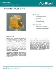
Millimeter-Wave Technology & DesignMultipliersMODEL PRODUCT NAME PERFORMANCE/CAPABILITY SUMMARYMUD Fullband FrequencyDoublerThe series MUD frequency doubler is a balanced resistive modemultiplier cover<strong>in</strong>g the full waveguide band from WR-28 to WR-06. The correspond<strong>in</strong>g output frequency range is 26.5 to 170GHz and the output power flatness is typically ± 2.0 dB acrossthe waveguide band. This frequency doubler is offered <strong>in</strong> twoversions, a standard and high power version. The standardversion produces an output power of -15 to +3 dBm, depend<strong>in</strong>gupon the <strong>in</strong>put power level and frequency range. The high powerversion produces an output power of 0 dBm to 10 dBm across an<strong>in</strong>put power range of 21 to 24 dBm, dependent on the frequencyrange.MUT Fullband Frequency Tripler The series MUT frequency triplers are balanced resistive modemultipliers cover<strong>in</strong>g full waveguide bands. Power flatness overthe full waveguide band for a given <strong>in</strong>put power level is typically±2.0 dB.AMC Active Multiplier Cha<strong>in</strong> The series AMC active multiplier cha<strong>in</strong> is a MMIC basedmultiplier that extends the range of sweepers or synthesizersfrom 8.25 – 20 GHz up to 140 GHz <strong>in</strong> eight waveguide bands.The AMC can also be <strong>in</strong>tegrated with other multipliers, such asseries MUD and MUT, to extend the frequency range up to 220GHz.19Millitech, Inc. •Tel: (413) 582-9620 • Fax: (413) 582-9622 • Email: <strong>in</strong>fo@millitech.com
ModelMillimeter-Wave Technology & Design(MUD) Fullband Frequency DoublerOutput frequency band and range(GHz)Input frequency range (GHz)Electrical SpecificationsMUD-28 MUD-22 MUD-15 MUD-10 MUD-06Ka26.5-4013.25-20Q33-50V50-75W75-110D110-17016.5-25 25-37.5 37.5-55 55-85Third harmonic content (dBc) (typ) -25 -25 -25 -25 -25<strong>Standard</strong> VersionInput power range (dBm) (m<strong>in</strong>/max) 10/18 10/18 10/18 10/18 7/16Conversion loss @ 16 dBm <strong>in</strong>put (dB)(typ)High Power Version17 18 20 22 20Input power range (dBm) (m<strong>in</strong>/max) 20/23 20/23 20/23 20/23 ---Conversion loss (dB) (typ) 15 15 16 16 --- Power output specifications apply over waveguide band. Output power can be optimized over narrower frequency range. Series MUD-06 tested at 13 dBm <strong>in</strong>put power (max allowed <strong>in</strong>put power is 16 dBm). Performance is over 50% waveguide bandwidth, please specify.For more product <strong>in</strong><strong>format</strong>ion, search series MUD at www.millitech.com(MUT) Fullband Frequency TriplerElectrical SpecificationsModel Number MUT-22 MUT-19 MUT-15 MUT-10 MUT-08 MUT-06Frequency band and range (GHz)Q U V W F D33-50 40-60 50-75 75-110 90-140 110-170Input frequency range (GHz) 11-16.67 13.33-20 16.67-25 25-36.6730- 36.67-46.67 56.67Input VSWR (typ) 2.5:1 2.5:1 2.5:1 2.5:1 Second harmonic content (dBc) (typ) -30 -30 -30 -30 Fourth harmonic content (dBc) (typ) -20 -20 -20 -20 <strong>Standard</strong> VersionInput power range (dBm) (m<strong>in</strong>/max) 10/18 10/18 10/18 10/18 7/16 7/16Conversion loss (dB) @ 16 dBm <strong>in</strong>put(typ) 20 21 22 24 High Power VersionInput power range (dBm) (m<strong>in</strong>/max) 20/23 20/23 20/23 20/23 --- ---Conversion loss (dB) (typ) 15 15 16 16 --- --- Series MUT-08, MUT-06, and MUT-05 tested at 13 dBm typical <strong>in</strong>put power (maximum allowed <strong>in</strong>put power is 16 dBm). Performance is over 50% waveguide bandwidth, please specify. Please consult Millitech for details.For more product <strong>in</strong><strong>format</strong>ion, search series MUT at www.millitech.com20Millitech, Inc. •Tel: (413) 582-9620 • Fax: (413) 582-9622 • Email: <strong>in</strong>fo@millitech.com
Millimeter-Wave Technology & Design(AMC) Active Multiplier Cha<strong>in</strong>Electrical SpecificationsModel Number AMC-KK-CFH00 AMC-28-SFH00 AMC-22-RFH00Output frequency (GHz) 20 to 40 26.5 to 40 33 to 50Input frequency (GHz) 10 to 20 13.25 to 20 8.25 to 12.50Multiplication factor 2 2 4Input Power (dBm) +3 +3 +3Output power See plots below See plots below See plots belowSignal purity (max) -20 dBc -20 dBc -20 dBcDC <strong>in</strong>put (typ) 8 – 12 V @ 750 mA 8 – 12 V @ 750 mA 8 – 12 V @ 600 mAModel Number AMC-19-RFH00 AMC-15-RFH00 AMC-12-RFH0AOutput frequency (GHz) 40 to 60 50 to 75 60 to 90Input frequency (GHz) 10 to 15 12.50 to 18.75 7.5 to 11.25Multiplication factor 4 4 8Input Power (dBm) +3 +3 +3Output power See plots below See plots below See plots belowSignal purity (max) -20 dBc -20 dBc -20dBcDC <strong>in</strong>put (typ) 8 – 12 V @ 650 mA 8 – 12 V @ 750 mA 8 – 12 V @ 1.2AModel Number AMC-10-RFH00 AMC-10-RFH20 AMC-10-RFHB0Output frequency (GHz) 75 to 110 75 to 110 75 to 110 6Input frequency (GHz) 12.50 to 18.33 6.25 to 9.15 12.50 to 18.33Multiplication factor 6 12 6Input Power (dBm) +3 +3 +3Output power See plots below See plots below See plots belowSignal purity (max) -20dBc -20 dBc -20 dBcDC <strong>in</strong>put (typ) 8 – 12 V @ 750 mA 8 – 12 V @ 850 mA 8 – 12 V @ 880 mAModel Number AMC-08-RFH00 AMC-05-RFH00 AMC-03-RFH00Output frequency (GHz) 90 to 140 140 to 220 220 to 325Input frequency (GHz) 11.25 to 17.5 11.67 to 18.33 12.22 to 18.06Multiplication factor 8 12 18Input Power (dBm) +3 +3 +3Output power See plots below See plots below See plots belowSignal purity (max) -20 dBc -20 dBc -20dBcDC <strong>in</strong>put (typ) 8 – 12 V @ 1A 8 – 12 V @ 1A 8 – 12 V @ 900 mANotes:1. The units must be heat sunk to keep the case temperature at or below +45°C.2. If required, heats<strong>in</strong>ks can be omitted. See “How To Order” section on website.3. All test<strong>in</strong>g will be at room temperature.4. The output power is saturated.5. The maximum DC <strong>in</strong>put current is 100 mA above the typical values.6. A narrow band version exists called the AMC-10-RNHB0, see below for plot.For more product <strong>in</strong><strong>format</strong>ion, search series AMC at www.millitech.com21Millitech, Inc. •Tel: (413) 582-9620 • Fax: (413) 582-9622 • Email: <strong>in</strong>fo@millitech.com
Millimeter-Wave Technology & Design(AMC) Active Multiplier Cha<strong>in</strong>Typical PerformanceOutput Power (dBm)AMC-KK-CFH00302826typ24222018m<strong>in</strong>1614121020 25 30 35 40Frequency (GHz)Output Power (dBm)AMC-28-SFH003028typ2624m<strong>in</strong>2220181614121026 28 30 32 34 36 38 40Frequency (GHz)Output Power (dBm)AMC-22-RFH0018161412typ108m<strong>in</strong>642033 34 35 36 37 38 39 40 41 42 43 44 45 46 47 48 49 50Frequency (GHz)Output Power (dBm)181614121086420AMC-15-RFH00m<strong>in</strong>typ50 55 60 65 70 75Frequency (GHz)22Millitech, Inc. •Tel: (413) 582-9620 • Fax: (413) 582-9622 • Email: <strong>in</strong>fo@millitech.com
Millimeter-Wave Technology & Design(AMC) Active Multiplier Cha<strong>in</strong>Typical PerformanceNote: The plot for the AMC-10-RFH00 applies to both6X and 12x (AMC-10-RFH20) multiplier versions Note: The AMC-10-RFHB0 DC <strong>in</strong>put is 8-12V @ .880AAMC-08-RFH00Note: The AMC-10-RNHB0 DC <strong>in</strong>put is 8-12V @ 1AOutput Power (dBm)1086420-2-4-6-8-10typm<strong>in</strong>90 100 110 120 130 140Frequency (GHz)For more product <strong>in</strong><strong>format</strong>ion, search series AMC at www.millitech.com23Millitech, Inc. •Tel: (413) 582-9620 • Fax: (413) 582-9622 • Email: <strong>in</strong>fo@millitech.com
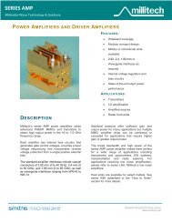
Amplifier and OscillatorMillimeter-Wave Technology & DesignMODEL PRODUCT NAME PERFORMANCE/CAPABILITY SUMMARYGDM Mechanically-Tuned GunnOscillatorThe series GDM mechanically-tuned Gunn oscillator isspecifically designed to provide repeatable mechanical tun<strong>in</strong>gcharacteristics by means of a micrometer drive. High poweroutput is achieved with m<strong>in</strong>imal output power variation over theentire tun<strong>in</strong>g range. The oscillator provides broad tun<strong>in</strong>g rangeGDVVoltage-Controlled GunnOscillatorwith comparable output power from WR-28 to WR-10.The series GDV voltage-controlled Gunn oscillator provideselectronic tun<strong>in</strong>g characteristics by suitably coupl<strong>in</strong>g a Gunndevice to a tun<strong>in</strong>g varactor. Series GDV provides performancecapabilities rang<strong>in</strong>g from nom<strong>in</strong>al electrical tun<strong>in</strong>g to very widetun<strong>in</strong>g bandwidths. The oscillator is available from 26.5 to 100GHz.LNA Low Noise Amplifier Millitech manufactures a l<strong>in</strong>e of standard, <strong>in</strong>-l<strong>in</strong>e, low noiseamplifiers <strong>in</strong> the 18 to 110 GHz range. These amplifiers utilizethe latest <strong>in</strong> MMIC technology and are designed for easy<strong>in</strong>tegration <strong>in</strong>to nearly any millimeter-wave application whileprovid<strong>in</strong>g state-of-the-art performance. These units are manufactured<strong>in</strong> compact packages.AMP Power Amplifier Millitech manufactures a l<strong>in</strong>e of standard, <strong>in</strong>-l<strong>in</strong>e, poweramplifiers <strong>in</strong> the 18 to 110 GHz range. These amplifiers utilizethe latest <strong>in</strong> MMIC technology and are designed for easy<strong>in</strong>tegration <strong>in</strong>to nearly any millimeter-wave application whileprovid<strong>in</strong>g state-of-the-art performance.<strong>Standard</strong> AMP/LNAPackage10 Watt Pulsed Amplifier24Millitech, Inc. •Tel: (413) 582-9620 • Fax: (413) 582-9622 • Email: <strong>in</strong>fo@millitech.com
Millimeter-Wave Technology & Design(GDM) Mechanically - Tuned Gunn OscillatorElectrical SpecificationsModel Number GDM-28 GDM-22 GDM-19 GDM-15 GDM-12 GDM-10Frequency range (GHz) 26.5-40 33-50 40-50 50-60 50-60 60-75 60-75 75-90 75-90 90-100Typical DC supply (V/mA) 5/1000 5/1000 5/1000 5/1000 5/1000 5/1000 5/1000 5/1000 5/1000 5/1000Typical frequency stability(MHz/°C)2 3 3 3 3 4 4 5 5 5Typical power stability(dB/°C)-0.02 -0.02 -0.02 -0.03 -0.03 -0.03 -0.03 -0.04 -0.04 -0.04<strong>Standard</strong> Version (±1% tun<strong>in</strong>g or less), Available power (dBm) (m<strong>in</strong>) 25 24 23 18 18 17 17 17 17 16Maximum Tun<strong>in</strong>g Version Available power (dBm) (m<strong>in</strong>) 20 19 19 17 17 17 16 16 16 10Tun<strong>in</strong>g bandwidth (GHz) 4 4 4 4 4 4 4 4 4 4 Center frequency tolerance ±100 MHz unless otherwise specified. Many comb<strong>in</strong>ations of mechanical tun<strong>in</strong>g range and output power are possible.These versions are representative examples. Many requirementsbeyond these standard ranges can be met. Contact Millitech for more <strong>in</strong><strong>format</strong>ion. Power output and tun<strong>in</strong>g range are critically dependent on the actual centerfrequency <strong>in</strong> this frequency range. Please contact Millitech for details. Please contact Millitech for wider tun<strong>in</strong>g options. Gunn Voltage is determ<strong>in</strong>ed at test and can vary from 4.0 to 6.0V. Optionalvoltage regulator is available.NOTE: Please contact Millitech for a solution to your specific requirements.For more product <strong>in</strong><strong>format</strong>ion, search series GDM at www.millitech.com(GDV) Voltage – Controlled Gunn OscillatorElectrical Specifications (Vgunn = 4 to 6V, Vvaractor = Vgunn to -20V, Igunn = 1.0A(typ))Model Number GDV-28 GDV-22 GDV-19 GDV-15 GDV-12 GDV-10Frequency Range (GHz) 26.5-40 33-40 40-50 40-50 50-60 50-60 60-75 60-75 75-90 75-90 90-100Typical frequency stability (MHz/°C) 2 2 3 3 4 4 4 4 5 5 5Typical power stability (dB/°C) 0.03 0.03 0.03 0.03 0.03 0.03 0.04 0.04 0.04 0.04 0.04Narrow Tun<strong>in</strong>g Version (±100 MHz) Available power (dBm) (m<strong>in</strong>) 23 23 21 21 19 19 17 17 15 15 13Moderate Tun<strong>in</strong>g Version (±500 MHz) Available power (dBm) (m<strong>in</strong>) 21 21 19 19 17 17 15 15 13 13 12 Center frequency tolerance ±100 unless otherwise specified. Many comb<strong>in</strong>ations of mechanical tun<strong>in</strong>g range and output power are possible. These versions arerepresentative examples. Many requirements beyond these standard ranges can be met. ContactMillitech for more <strong>in</strong><strong>format</strong>ion. Gunn Voltage determ<strong>in</strong>ed at test. Optional voltage regulator available.NOTE: Please contact Millitech for a solution to your specific requirements.For more product <strong>in</strong><strong>format</strong>ion, search series GDV at www.millitech.com25Millitech, Inc. •Tel: (413) 582-9620 • Fax: (413) 582-9622 • Email: <strong>in</strong>fo@millitech.com
Millimeter-Wave Technology & Design(LNA) Low Noise AmplifierMillitech’s AMP series amplifier offer<strong>in</strong>gs are contantly be<strong>in</strong>g updated as we work to supply the latest State of the Artperformance to our customers. Please visit our website for a current list<strong>in</strong>g. Millitech is constantly prepar<strong>in</strong>g new AMP products.Please contact Millitech if you do not f<strong>in</strong>d what you need.For more product <strong>in</strong><strong>format</strong>ion, search series LNA at www.millitech.com(AMP) Power AmplifierMillitech’s LNA series amplifier offer<strong>in</strong>gs are constantly be<strong>in</strong>g updated as we work to supply the latest State of the Artperformance to our customers. Please visit our website for a current list<strong>in</strong>g. Millitech is constantly prepar<strong>in</strong>g new AMP products.Please contact Millitech if you do not f<strong>in</strong>d what you need.For more product <strong>in</strong><strong>format</strong>ion, search series AMP at www.millitech.com26Millitech, Inc. •Tel: (413) 582-9620 • Fax: (413) 582-9622 • Email: <strong>in</strong>fo@millitech.com
Millimeter-Wave Technology & DesignMODEL PRODUCT NAME PERFORMANCE/CAPABILITY SUMMARYPSP S<strong>in</strong>gle-Pole S<strong>in</strong>gle-ThrowPIN SwitchThe series PSP s<strong>in</strong>gle-pole, s<strong>in</strong>gle-throw (SPST) PIN switchcovers 18 to 110 GHz <strong>in</strong> seven waveguide bands. Fullwaveguide bandwidth is available up to 75 GHz. Theavailable bandwidth is 10 GHz <strong>in</strong> the range of 75 to 100 GHz.The standard switch<strong>in</strong>g speed is 150 ns (typical) fromisolation to PASS state and 20 ns from <strong>in</strong>sertion loss state toisolation. The <strong>in</strong>sertion loss is 1.2 dB (max) <strong>in</strong> K-Band, and<strong>in</strong>creases to 2.2 dB (max) <strong>in</strong> W-Band. The standard isolationis 30 dB <strong>in</strong> K-Band, and drops to 20 dB <strong>in</strong> W-Band. PSP is aPSHPDTVCAHigh Speed S<strong>in</strong>gle-PoleS<strong>in</strong>gle-Throw PIN SwitchS<strong>in</strong>gle-Pole Double-ThrowPIN SwitchVoltage-ControlledVariable AttenuatorControl Componentsreflective device.The series PSH high speed, s<strong>in</strong>gle-pole, s<strong>in</strong>gle-throw (SPST)PIN switch covers 18 to 95 GHz <strong>in</strong> seven waveguide bands.The switch covers full waveguide band up to 40 GHz. Thebandwidth drops to 5 GHz at 95 GHz. The standard switch<strong>in</strong>gspeed is 2 ns (max) with a driver propagation delay of 8 ns(typical). It is available with or without an <strong>in</strong>tegral driver.Isolation levels range from 30 dB <strong>in</strong> K-Band to 18 dB <strong>in</strong> W-Band. PSH is a reflective device.The series PDT s<strong>in</strong>gle-pole, double-throw (SPDT) PIN switchcovers 18 to 100 GHz <strong>in</strong> seven waveguide bands. Fullwaveguide bandwidth is available up to 75 GHz. Theavailable bandwidth is 10 GHz <strong>in</strong> the range of 60 to 100 GHz.The standard switch<strong>in</strong>g speed is 300 ns (typical) fromisolation to PASS state and 20 ns from <strong>in</strong>sertion loss state toisolation. The <strong>in</strong>sertion loss is 1.8 dB (max) <strong>in</strong> K-Band, and<strong>in</strong>creases to 3 dB (max) <strong>in</strong> W-Band. The isolation is 22 dB <strong>in</strong>K-Band and drops to 18 dB <strong>in</strong> W-Band. Series PDT isavailable <strong>in</strong> “Y” configurations. WR-28 and WR-10 models arealso available <strong>in</strong> “<strong>in</strong>-l<strong>in</strong>e” configurations. PDT is a reflectivedevice.The series VCA voltage-controlled variable attenuator covers18 to 100 GHz <strong>in</strong> seven waveguide bands. Full waveguidebandwidth is available up to 75 GHz. The bandwidth is 10GHz above 75 GHz. This attenuator offers an attenuationdynamic range of 25 dB up to 50 GHz, and 20 dB at 100 GHz.Series VCA is also offered <strong>in</strong> a high attenuation version, <strong>in</strong>which the attenuation dynamic range is 25 to 40 dB,depend<strong>in</strong>g upon the frequency. However <strong>in</strong>sertion loss isslightly higher. VCA is a reflective device.27Millitech, Inc. •Tel: (413) 582-9620 • Fax: (413) 582-9622 • Email: <strong>in</strong>fo@millitech.com
Millimeter-Wave Technology & Design(PSP) S<strong>in</strong>gle-Pole S<strong>in</strong>gle-Throw PIN SwitchModelFrequency band and range(GHz)PSP-42K18-26.5PSP-28Ka26.5-40PSP-22Q33-50PSP-19U40-60PSP-15V50-75PSP-12E60-90PSP-10W75-110Bandwidth (GHz) (max)* 10 10 10 10 10 10 10<strong>Standard</strong> VersionInsertion loss (dB) (max) 1.2 1.5 1.5 1.8 2.0 2.0 2.2Isolation (dB) (m<strong>in</strong>) 30 30 30 25 20 20 20High Isolation VersionElectrical SpecificationsInsertion loss (dB) (max) 2.0 2.2 2.4 2.5 2.7 2.7 3.7Isolation (dB) (m<strong>in</strong>) 40 40 35 35 30 27 25Performance Specifications (all bands)Switch<strong>in</strong>g speed (rise/fall): 20/150 ns (typ) (10% to 90%)Driver propagation delay: 10 ns (max)VSWR (“on” state):2:1 (max)Power handl<strong>in</strong>g (CW/peak): 0.5/10 W (max)Current:5 V @ 20 mA, -5 to -12 V @ 5 mA* For wider bandwidth please consult Millitech.Note: Driver control <strong>in</strong>put is TTL compatible with SMA connector.For more product <strong>in</strong><strong>format</strong>ion, search series PSP at www.millitech.com(PSH) High Speed S<strong>in</strong>gle-Pole S<strong>in</strong>gle-Throw PIN SwitchModelFrequency band and range (GHz)PSH-42 PSH-28 PSH-22 PSH-19 PSH-15 PSH-12 PSH-10K18-26.5Ka26.5-40Q33-50U40-6028Millitech, Inc. •Tel: (413) 582-9620 • Fax: (413) 582-9622 • Email: <strong>in</strong>fo@millitech.comV50-75E60-90W75-95Bandwidth (GHz) (max) FULL 10 10 6 6 5 5Insertion loss (dB) (max) 2.0 2.0 2.5 2.5 2.5 3 3.5Isolation (dB) (m<strong>in</strong>) 30 30 30 25 20 20 18Switch<strong>in</strong>g speed (ns) (typ) 2 2 2 2 2 2 2Driver propagation delays (ns) (max) 8 8 8 8 8 8 8VSWR (max) 2:1 2:1 2:1 2:1 2:1 2:1 2:1Power handl<strong>in</strong>g (CW/peak, W) (max) 0.25/5 0.25/5 0.25/5 0.25/5 0.25/5 0.25/5 0.25/5DC bias <strong>in</strong>put(V/mA)Electrical SpecificationsPositive supply +5/20 +5/20 +5/20 +5/20 +5/20 +5/20 +5/20Negative supply -5/5 -5/5 -5/5 -5/5 -5/5 -5/5 -5/5 Switch<strong>in</strong>g speed specifications apply to any switch/driver comb<strong>in</strong>ation. Driver propagation delay not <strong>in</strong>cluded.Switch<strong>in</strong>g speed is driver dependent. Measured <strong>in</strong> PASS state only. Driver control <strong>in</strong>put is TTL compatible with an SMA connector.For more product <strong>in</strong><strong>format</strong>ion, search series PSH at www.millitech.com
(PDT) S<strong>in</strong>gle-Pole Double-Throw PIN SwitchElectrical SpecificationsMillimeter-Wave Technology & DesignModel WR-42 WR-28 WR-22 WR-19 WR-15 WR-12 WR-10Frequency band and range (GHz)K18-26.5Ka26.5-40Q33-50U40-60V50-75E60-90Bandwidth (GHz) (max) 10 10 10 10 10 10 10W75-100Insertion loss (dB) (max) 1.8 2.0 2.0 2.5 2.5 3.0 2.7Isolation (dB) (m<strong>in</strong>) 22 22 22 22 22 19 18Performance Specifications (all bands)Switch<strong>in</strong>g speed (rise/fall): 20/300 ns (typical) (10% to 90%)Driver propagation delay: 10 ns (max) <strong>in</strong> addition to switch<strong>in</strong>g speedPower handl<strong>in</strong>g (CW/peak): 0.5/10 W (max)Current:5 V @ 20 mA, -5 to -12 V @ 5 mANotes: Maximum bandwidth offered. Superior performance for narrower bandwidth. Driver propagation delay (10 ns max) not <strong>in</strong>cluded. Switch<strong>in</strong>g speed is driver dependent.For more product <strong>in</strong><strong>format</strong>ion, search series PDT at www.millitech.com(VCA) Voltage - Controlled Variable AttenuatorElectrical Specifications Measured <strong>in</strong> PASS state only.ModelFrequency band and range (GHz)VCA-42 VCA-28 VCA-22 VCA-19 VCA-15 VCA-12 VCA-10K18-26.5Ka26.5-40Q33-50U40-60V50-75E60-90W75-100<strong>Standard</strong> Attenuation Version with DriverBandwidth (GHz) 6 10 10 10 10 10 10Insertion loss at 0 V (dB) (typ) 1.4 1.7 1.7 2.0 2.2 2.2 2.2M<strong>in</strong>imum attenuation at 10 V (dB) 30 30 30 25 20 20 20VSWR (max)* 2:1 2:1 2:1 2:1 2:1 2:1 2:1Power handl<strong>in</strong>g (CW/peak, W) (max) 0.5/10 0.5/10 0.5/10 0.5/10 0.5/10 0.5/10 0.5/10DC bias <strong>in</strong>put (V/mA) ±12/20 ±12/20 ±12/20 ±12/20 ±12/20 ±12/20 ±12/20Control voltage (V) 0-10 0-10 0-10 0-10 0-10 0-10 0-10High Attenuation Version with DriverBandwidth (GHz) 6 10 10 10 10 10 10Insertion loss at 0 V (dB) (typ) 2.2 2.5 2.5 2.8 3.0 3.0 3.0M<strong>in</strong>imum attenuation at 10 V (dB) 40 40 40 35 30 30 25VSWR (max)* 2:1 2:1 2:1 2:1 2:1 2:1 2:1Power handl<strong>in</strong>g (CW/peak) (max) 0.5/10 0.5/10 0.5/10 0.5/10 0.5/10 0.5/10 0.5/10DC bias <strong>in</strong>put (V/mA) ±12/40 ±12/40 ±12/40 ±12/40 ±12/40 ±12/40 ±12/40Control voltage (V) 0-10 0-10 0-10 0-10 0-10 0-10 0-10For more product <strong>in</strong><strong>format</strong>ion, search series VCA at www.millitech.com29Millitech, Inc. •Tel: (413) 582-9620 • Fax: (413) 582-9622 • Email: <strong>in</strong>fo@millitech.com
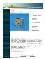
Millimeter-Wave Technology & DesignMODEL PRODUCT NAME PERFORMANCE/CAPABILITY SUMMARYFBI Fullband Isolator The series FBI full waveguide band isolator is a Faraday rotation ferritedevice. This isolator is offered from 18 to 220 GHz <strong>in</strong> ten waveguidebands. The isolator consists of a section of waveguide conta<strong>in</strong><strong>in</strong>g lowloss ferrite material and impedance match<strong>in</strong>g elements. The isolatorhas a maximum <strong>in</strong>sertion loss of 1.5 dB <strong>in</strong> K-Band and 4.5 dB <strong>in</strong> G-Band. The correspond<strong>in</strong>g isolation is 25 and 20 dB.JFDFerrite Isolator andCirculatorFerrite and Filter <strong>Products</strong>The series JFD junction ferrite isolator and circulator covers the frequencyrange from 18 to 100 GHz <strong>in</strong> seven waveguide bands. Theisolator and circulator provide high isolation and low <strong>in</strong>sertion <strong>in</strong> arelatively small package. These units are available <strong>in</strong> twoconfigurations: s<strong>in</strong>gle-junction and triple-junction.WBI Wide Band Isolator The series WBI wide band isolators provide an ideal solution forapplications <strong>in</strong> broadband <strong>in</strong>struments and systems, swept frequencyapplications and cryogenically cooled radio telescopes. These isolatorsfeature low <strong>in</strong>sertion loss and high isolation <strong>in</strong> a compact size. Theyare also ideal for applications where space is at a premium.FLP Low Pass Filter The series FLP low pass filter provides high rejection and excellentselectivity for frequencies above the corner frequency. The filter covers18 to 110 GHz <strong>in</strong> seven waveguide bands. The <strong>in</strong>sertion loss is 1 dB <strong>in</strong>K-Band and <strong>in</strong>creases to 1.6 dB (max) <strong>in</strong> W-Band. The waveguide cutofffrequency determ<strong>in</strong>es the rejection at the lower band edge. Thisfilter has a wide stopband, reject<strong>in</strong>g up to three times the highestpassband frequency.FIB Iris Bandpass Filter The series FIB narrow bandpass filter has a passband bandwidth <strong>in</strong>the range of 1% to 25% of center frequency. The filter offers low<strong>in</strong>sertion loss <strong>in</strong> the passband and a high degree of selectivity. Forexample, the typical <strong>in</strong>sertion loss for a filter with 2% passbandbandwidth <strong>in</strong> Ka-Band is 1.5 dB. Characteristics can be tailored to suitspecific rejection requirements. The series FIB is available <strong>in</strong> n<strong>in</strong>ewaveguide bands from 18 to 220 GHz.FNP Narrow Bandpass Filter The series FNP narrow bandpass filter has a passband bandwidth <strong>in</strong>the range of 2% to 5% of center frequency. The filter offers low<strong>in</strong>sertion loss <strong>in</strong> the passband and a high degree of selectivity. Forexample, the typical <strong>in</strong>sertion loss for a filter with 2% passbandbandwidth <strong>in</strong> Ka-Band is 1.8 dB. Characteristics can be tailored to suitspecific rejection requirements. The series FNP is available <strong>in</strong> eightwaveguide bands from 18 to 140 GHz.FHP High Pass Filter The series FHP high pass filter is designed and constructed to providea sharp skirt selectivity of low frequency with m<strong>in</strong>imum <strong>in</strong>sertion loss <strong>in</strong>the passband. The typical <strong>in</strong>sertion loss is 0.7 dB <strong>in</strong> K-Band, and<strong>in</strong>creases to about 1.5 dB <strong>in</strong> W-Band. The <strong>in</strong>sertion loss is determ<strong>in</strong>edby the corner frequency and selectivity. This filter is available <strong>in</strong> eightwaveguide bands from 18 to 140 GHz. The filter characteristics can betailored to meet specific rejection requirements.HPC High Power Circulator Millitech series HPC junction ferrite devices (circulators) cover thefrequency range from 18 to 110 GHz. The circulator is a four-port,differential phase shift device which can be configured as an isolatorby term<strong>in</strong>at<strong>in</strong>g two of the ports. The high isolation, low <strong>in</strong>sertion loss,low VSWR (high return loss), and high power handl<strong>in</strong>g typical of theseferrite devices make them ideal for use with frequency sources,amplifiers, and receivers.30Millitech, Inc. •Tel: (413) 582-9620 • Fax: (413) 582-9622 • Email: <strong>in</strong>fo@millitech.com
Millimeter-Wave Technology & Design(FBI) Fullband IsolatorElectrical SpecificationsModel Number FBI-42 FBI-28 FBI-22 FBI-19 FBI-15 FBI-12 FBI-10 FBI-08 FBI-06 FBI-05Frequency band and range K Ka Q U V E W F D G(GHz)18-26.5 26.5-40 33-50 40-60 50-75 60-90 75-110 90-140 110-170 140-220Insertion loss (dB) (max) 1.5 1.5 1.5 1.7 1.8 2.0 2.5 2.8 3.2 4.0Insertion loss (dB) (typ) 1.0 1.0 1.1 1.2 1.6 1.7 2.0 2.2 2.9 3.5Isolation (dB) (m<strong>in</strong>) 25 27 27 27 27 27 27 20 20 20Input/Output VSWR (max) 1.4:1 1.4:1 1.4:1 1.4:1 1.4:1 1.4:1 1.4:1 1.4:1 1.4:1 1.4:1Power rat<strong>in</strong>g (W) (max) 3.0 2.5 2.0 1.5 1.5 1.0 1.0 0.75 0.75 0.75 The performance of G-band (WR-05) isolators is measured at selected frequencieswith<strong>in</strong> the band. Performance specifications given above are typical values measured<strong>in</strong> the frequency band.For more product <strong>in</strong><strong>format</strong>ion, search series FBI at www.millitech.comModel JFD-42 JFD-28 JFD-22 JFD-19 JFD-15 JFD-12 JFD-10Frequency band andrange (GHz)K18-26.5Ka26.5-40S<strong>in</strong>gle Junction Units (Partial band/Fullband) Bandwidth (GHz) (max)Q33-50U40-60V50-7531Millitech, Inc. •Tel: (413) 582-9620 • Fax: (413) 582-9622 • Email: <strong>in</strong>fo@millitech.comE60-90W75-1002.0/8.5 2.0/13.5 2.0 2.0 2.0 2.0 2.0Isolation (dB) (m<strong>in</strong>) 20/20 20/18 20 20 20 20 20Insertion loss (dB) (max) 0.3/0.4 0.5/0.6 0.5 0.6 0.7 0.8 0.8VSWR (max) 1.2:1/1.3:1 1.2:1/1.4:1Power rat<strong>in</strong>g (W) (max)Triple Junction Isolators(JFD) Ferrite Circulator and IsolatorElectrical Specifications1.2:1 1.3:1 1.3:1 1.3:1 1.3:110 10 8 7 6 5 5Bandwidth (GHz) (max) --- 2.0 2.0 2.0 2.0 2.0 2.0Isolation (dB) (m<strong>in</strong>) --- 50 50 50 50 50 50Insertion loss (dB) (max) --- 1.2 1.3 1.6 1.9 2.2 2.5VSWR (max) --- 1.2:1 1.2:1 1.2:1 1.3:1 1.3:1 1.3:1Power rat<strong>in</strong>g (W) (max) --- 10 8 7 6 5 5 Full waveguide bandwidth units available <strong>in</strong> K- and Ka-Bands (WR-42 and WR-28) only. For broader bandwidths <strong>in</strong> other bands, pleasesee series WBI or consult Millitech for details. Maximum bandwidth offered for the standard product. Please specify bandwidth requirement. Load VSWR 3:1 or better. 1 GHz bandwidth for frequencies above 96 GHz.Note: Wider bandwidth is available as a special order. Please consult Millitech for details.For more product <strong>in</strong><strong>format</strong>ion, search series JFD at www.millitech.com
(WBI) Wide Band IsolatorModel(FIB) Iris Bandpass FilterMillimeter-Wave Technology & DesignModel FIB-42 FIB-28 FIB-22 FIB-19 FIB-15 FIB-12 FIB-10 FIB-08 FIB-06 FIB-05Frequency band andrange (GHz)Electrical Specifications K18-26.5Ka26.5-40Q33-50WBI-10Operational frequency range (GHz) 82-110Insertion loss (dB) (max) 1.3Insertion loss at 80K (dB) (typ) 0.6Isolation (dB) (m<strong>in</strong>) 20VSWR (max) 1.5:1 At ambient temperature only. Includes mismatch due to port configuration.Note: Can be tuned for cryogenic operation, but tested atambient temperatures. Functional 75-115 GHz specifydesired range.U40-60V50-75E60-90(FLP) Low Pass FilterModel FLP-42 FLP-28 FLP-22Frequency band and range (GHz)W75-110K18-26.5F90-140Ka26.5-40D110-170Q33-50G140-220FLP-19U40-60FLP-15V50-75FLP-12E60-90FLP-10W75-110Insertion loss (dB) (max) 1.0 1.0 1.0 1.0 1.2 1.4 1.6Upper band edge (f E ) (typ) (corner frequency)(GHz)28.3 41.2 52.0 62.0 77.0 93.0 105.0Rejection band (f H to f U ) (GHz) (typ) 34-66 49-95 62-120 74-143 92-178Waveguide cutoff frequency (f C ) (GHz) 14.1 21.1 26.3 31.4 39.9 48.4 59.1Custom <strong>Products</strong>Rejection range for high frequencies (f H to f U )(dB)Electrical Specifications111-214139-26322-55 25-50 25-45 25-40 25-40 25-40 25-40 Rejection band attenuation (f H to f U ): > 40 dB. Frequencies below this waveguide cut-off frequency are significantly attenuated. Typical rejection at 0.85 times cut-off frequency is 40 dB.Electrical SpecificationsPassbandInsertion loss (dB)Typ 0.25 0.25 0.3 0.35 0.35 0.45 0.6 Max 0.4 0.4 0.5 0.55 0.55 0.75 0.9 Low side rejectionlevel (dB) (m<strong>in</strong>) @ F RLHigh side rejection level(dB) (m<strong>in</strong>) @ F RH >50 >50 >50 >50 >50 >50 50 45 42 40 38 35 35 30 Passband VSWR 1.5:1 1.5:1 1.5:1 1.5:1 1.5:1 1.5:1 1.5:1 Data is based upon a 6-section, 10% filter. Many standard configurations available listed onl<strong>in</strong>e, please consult Millitech for further <strong>in</strong><strong>format</strong>ion.For more product <strong>in</strong><strong>format</strong>ion, search series WBI, FLP & FBI at www.millitech.com32Millitech, Inc. •Tel: (413) 582-9620 • Fax: (413) 582-9622 • Email: <strong>in</strong>fo@millitech.com
Millimeter-Wave Technology & Design(FNP) Narrow Bandpass FilterModel FNP-42 FNP-28 FNP-22 FNP-19 FNP-15 FNP-12 FNP-10 FNP-08Frequency band and range (GHz)Insertion loss (dB) (max)K18-26.5Electrical SpecificationsKa26.5-40Q33-50U40-60V50-75E60-90W75-110F90-1402% 1.8 1.8 1.8 1.8 2.0 2.0 2.2 4% 1.6 1.6 1.6 1.6 1.8 1.8 2.0 Low side rejection level (dB) (m<strong>in</strong>) @ F RL40 40 40 40 40 40 40 High side rejection level (dB) (m<strong>in</strong>) @ F RH30 30 30 30 30 30 30 Passband VSWR (typ) 1.5:1 1.5:1 1.5:1 1.5:1 1.5:1 1.5:1 1.5:1 Data is based upon a 5-section filter. Upper limit is ~ 6% bandwidth. <strong>Standard</strong> rejection frequencies (F RL and F RH ) are calculated at center frequency ± (1.5 xbandwidth <strong>in</strong> GHz). Please consult Millitech for further <strong>in</strong><strong>format</strong>ion.Note: Other bandwidth percentages are available upon request. (See series FIB for otherbandwidth requirements and options)ModelFrequency band and range (GHz)For more product <strong>in</strong><strong>format</strong>ion, search series FNP at www.millitech.com(FHP) High Pass FilterElectrical SpecificationsFHP-42 FHP-28 FHP-22 FHP-19 FHP-15 FHP-12 FHP-10 FHP-08K18-26.5Ka26.5-40Q33-50U40-60V50-75E60-90W75-110F90-140Range of cut-off frequency (band edge) (GHz) 14-23 21-35 25-44 31-52 40-64 48-80 59-95 116-125Passband loss (dB) (max) 0.7 1.0 1.0 1.2 1.3 1.3 1.5 2.0Rejection at 90% of cut-off frequency (dB) (typ) 45 45 40 40 40 35 35 35 Cut-off frequency has 3 dB loss (typical). Attenuation <strong>in</strong>creases rapidly below thisfrequency. Insertion loss passband is measured 4.0 GHz from the 3 dB cut-off frequency. Longer length is necessary to achieve greater attenuation. Please consultMillitech for details.For more product <strong>in</strong><strong>format</strong>ion, search series FHP at www.millitech.com33Millitech, Inc. •Tel: (413) 582-9620 • Fax: (413) 582-9622 • Email: <strong>in</strong>fo@millitech.com
Millimeter-Wave Technology & Design(HPC) High Power CirculatorElectrical SpecificationsModel Number HPC-42 HPC-28 HPC-22 HPC-19 HPC-15 HPC-12 HPC-10Frequency Band and Range(GHz)K18-26.5Ka26.5-40Q33-50U40-60V50-75E60-90W75-110Bandwidth 10% 10% 10% 10% 10% 10% 10%Isolation (dB) (typ) 20 20 20 20 20 20 20Insertion Loss (dB) (typical, mid-band) 0.6 0.8 0.9 1.0 1.1 1.2 1.3VSWR (typ) 1.3:1 1.3:1 1.3:1 1.3:1 1.3:1 1.3:1 1.3:1Average Power Rat<strong>in</strong>g (W) 200 200 200 200 200 200 200Peak Power Rat<strong>in</strong>g @ Sea Level (W) TBA TBA TBA TBA TBA TBA 2000 Maximum bandwidth offered for the standard products. Please specify bandwidth requirement. Measured Port 2 → Port 1 Load VSWR 3:1 or better. Please specify power requirements at time of order.Model NumberCenterFrequency(GHz)<strong>Standard</strong> Models<strong>Standard</strong> Models are items that require no setup fee.Bandwidth(GHz)Isolation(dB, typ.)VSWR(typ)AveragePowerRat<strong>in</strong>g (W)Peak PowerRat<strong>in</strong>g @ SeaLevel (W)HPC-28-S0350 35 3.5 20 1.3:1 200 TBDHPC-22-R0440 44 4.4 20 1.3:1 200 TBDHPC-12-R0730 73 7.3 20 1.3:1 200 TBDHPC-12-R0830 83 8.3 20 1.3:1 200 TBDHPC-10-R0940 94 9.4 20 1.3:1 200 2000 Contact Millitech for greater bandwidth. Measured Port 2 → Port 1For more product <strong>in</strong><strong>format</strong>ion, search series HPC at www.millitech.com34Millitech, Inc. •Tel: (413) 582-9620 • Fax: (413) 582-9622 • Email: <strong>in</strong>fo@millitech.com
Millimeter-Wave Technology & DesignMODEL PRODUCT NAME PERFORMANCE/CAPABILITY SUMMARYCGC Crossguide Coupler The series CGC compact crossguide directional couplers areoffered <strong>in</strong> the frequency range of 18 to 170 GHz. The nom<strong>in</strong>alcoupl<strong>in</strong>g value is 20 dB. Directivity ranges from 17 dB at the lowerend of the band to 12 dB at the high end for all three-port unitsbelow 110 GHz. For complete coverage of each waveguide, eachmodel (low, mid or high) provides nom<strong>in</strong>al performance over thewhole band, but meets the full specifications only over the specificportion of the waveguide band. These couplers are offered with thefourth port either <strong>in</strong>ternally term<strong>in</strong>ated or unterm<strong>in</strong>ated (accessible).CL33-Port High DirectivityDirectional CouplerThe series CL3 high directivity coupler covers 18 to 170 GHz <strong>in</strong> n<strong>in</strong>ewaveguide bands. The coupler is offered with coupl<strong>in</strong>g values of 3,6, 10, 20, 30 or 40 dB, and covers a full waveguide band. It hasdirectivity of 37 dB up to 60 GHz and drops to 28 dB up to 170 GHz.CMT Magic Tee Hybrid Coupler The series CMT magic tee hybrid coupler covers 18 to 170 GHz <strong>in</strong>n<strong>in</strong>e waveguide bands. Each coupler is offered <strong>in</strong> two versions, oneprovid<strong>in</strong>g a bandwidth of 60% and the other provid<strong>in</strong>g a bandwidthof 90%.CSS Short Slot Hybrid Coupler The series CSS short slot hybrid coupler covers 26.5 to 170 GHz <strong>in</strong>n<strong>in</strong>e waveguide bands. The two output ports are <strong>in</strong>-l<strong>in</strong>e to the <strong>in</strong>putport, and have 90° phase difference with nearly equal power levelsover 5% of the center frequency. Isolation between output ports is20 dB (typical).FXAPassive Waveguide <strong>Products</strong>General Purpose andPrecision Fixed AttenuatorThe series FXA general purpose fixed attenuator consists of awaveguide section with a precisely cut resistive vane. It is available<strong>in</strong> n<strong>in</strong>e waveguide bands from 18 to 170 GHz. The precision fixedattenuators are made us<strong>in</strong>g a rugged split block design. Thisattenuator can be used as a laboratory standard aga<strong>in</strong>st which other<strong>in</strong>struments or components are calibrated.LSA Level Set Attenuator The series LSA level set attenuator consists of a waveguide sectionwith a precisely cut resistive vane. The attenuator is available <strong>in</strong>n<strong>in</strong>e waveguide bands from 18 to 170 GHz.VPS Variable Phase Shifter The series VPS variable phase shifter consists of a waveguidesection with a movable dielectric vane driven by a micrometer. Thisarrangement provides a phase shift range of 180.WTR Term<strong>in</strong>ation The series WTR term<strong>in</strong>ation covers 18 to 220 GHz <strong>in</strong> 10 waveguidebands. The term<strong>in</strong>ation consists of tapered absorbers with<strong>in</strong> thewaveguide section. This term<strong>in</strong>ation is designed to provide amaximum VSWR rang<strong>in</strong>g from 1.03:1 <strong>in</strong> WR-42 to 1.5:1 <strong>in</strong> WR-05.TLD Tunable Load The series TLD tunable load covers 26.5 to 170 GHz <strong>in</strong> eightwaveguide bands. The tunable load consists of a metric micrometertun<strong>in</strong>g mechanism that allows the microwave absorber to bepositioned with<strong>in</strong> the guide while ma<strong>in</strong>ta<strong>in</strong><strong>in</strong>g a constant magnitudeof reflection coefficient. This tunable load is designed to provide atypical VSWR rang<strong>in</strong>g from 1.05:1 <strong>in</strong> WR-28 to 1.1:1 <strong>in</strong> WR-06.TSC Tunable Short The series TSC tunable short covers 26.5 to 170 GHz <strong>in</strong> eightwaveguide bands. The short consists of a movable non-contact<strong>in</strong>gchoke plunger with<strong>in</strong> a waveguide section. The series TSC providesVSWR <strong>in</strong> excess of 20:1 <strong>in</strong> WR-28 and 15:1 <strong>in</strong> WR-06.WCA Waveguide to Coax Adapter The series waveguide to coax adapters, cover up to 110 GHz.Waveguide to coax <strong>in</strong>clude 2.92, 2.44, 1.85, and 1.0 mmconnectors.35Millitech, Inc. •Tel: (413) 582-9620 • Fax: (413) 582-9622 • Email: <strong>in</strong>fo@millitech.com
(CGC) Crossguide CouplerMillimeter-Wave Technology & DesignElectrical SpecificationsModel Number CGC-42 CGC-28 CGC-22 CGC-19 CGC-15 CGC-12 CGC-10 CGC-08 CGC-06Frequency band and range (GHz)K Ka Q U V E W F D18-26.5 26.5-40 33-50 40-60 50-75 60-90 75-110 90-140 110-170Lowband 18-22 26.5-31 33-40 40-48 50-60 60-72 75-89 90-110 110-134Bandwidth (GHz) Midband 20-24 29-35 38-45 46-54 57-67 69-81 85-99 105-125 128-152Highband 23-26.5 34-40 43-50 52-60 65-75 78-90 96-110 120-140 146-170Coupl<strong>in</strong>g value (dB) (typ) 20 20 20 20 20 20 20 20 20Coupl<strong>in</strong>g flatness (±dB) (max) 1.5 1.5 1.5 1.5 1.5 1.5 1.5 1.5 1.5Insertion loss (dB) (max) 0.5 0.5 0.5 0.6 0.6 1.0 1.0 1.5 1.7Lowband 17 17 17 17 17 17 17 12 12Directivity (dB) (m<strong>in</strong>) Midband 15 15 15 15 15 15 15 12 12Highband 12 12 12 12 12 12 12 12 12Ma<strong>in</strong> l<strong>in</strong>e VSWR (max) 1.15:1 1.15:1 1.15:1 1.15:1 1.15:1 1.2:1 1.2:1 1.2:1 1.5:1Secondary l<strong>in</strong>e VSWR (max) 1.2:1 1.2:1 1.2:1 1.2:1 1.2:1 1.25:1 1.25:1 1.25:1 1.5:1 See series CL3/CL4 for fullband performance and greater directivity. Coupl<strong>in</strong>g value = -10 log 10 (P 3 /P 1 ). Nom<strong>in</strong>al ±2 dB 3-port version only. Coupl<strong>in</strong>g flatness for 4-port version is ±2.5 dB from K- to D-band. Insertion loss = -10 log 10 [(P 2 +P 3 )/P 1 ]. 3-port version only. Directivity for 4-port version is 12 dB from K- to W-band and 7 dB for F- to D Directivity = 10 log 10 (P 3 /P 1 ).For more product <strong>in</strong><strong>format</strong>ion, search series CGC at www.millitech.com(CL3) 3-Port High Directivity Directional CouplerModel Number CL3-42 CL3-28 CL3-22 CL3-19 CL3-15 CL3-12 CL3-10 CL3-08 CL3-06Frequency band and range (GHz)K Ka Q U V E W F D18-26.5 26.5-40 33-50 40-60 50-75 60-90 75-110 90-140 110-170Coupl<strong>in</strong>g value (dB), 10, 20Coupl<strong>in</strong>g flatness (±dB) (max) 0.7 0.7 0.7 0.7 0.7 0.7 0.7 0.7 0.7Insertion loss (dB) (max) 0.8 0.8 0.8 0.8 1.1 1.5 1.5 2.2 2.5Directivity (dB) (m<strong>in</strong>) 32 37 37 37 34 32 32 28 28Ma<strong>in</strong> l<strong>in</strong>e VSWR (max) 1.06:1 1.06:1 1.06:1 1.06:1 1.08:1 1.1:1 1.1:1 1.15:1 1.5:1Secondary l<strong>in</strong>e VSWR (max) 1.1:1 1.1:1 1.1:1 1.1:1 1.1:1 1.15:1 1.15:1 1.2:1 1.5:1Coupl<strong>in</strong>g value (dB) 30, 40Coupl<strong>in</strong>g flatness (±dB) (max) 0.7 0.7 0.7 0.7 0.7 0.7 0.7 0.7 0.7Insertion loss (dB) (max) 0.8 0.8 0.8 0.8 1.1 1.1 1.5 2.2 2.5Directivity (dB) (m<strong>in</strong>) 32 33 33 33 30 30 28 24 24Ma<strong>in</strong> l<strong>in</strong>e VSWR (max) 1.06:1 1.06:1 1.06:1 1.06:1 1.08:1 1.08:1 1.1:1 1.15:1 1.5:1Secondary l<strong>in</strong>e VSWR (max) 1.1:1 1.1:1 1.1:1 1.1:1 1.1:1 1.1:1 1.15:1 1.2:1 1.5:1 Coupl<strong>in</strong>g value =-10 log 10 (P 3 /P 1 ). For power dividers, please see series CSS or CMT. Applies to 20 dB units only. Add 0.5dB for 10dB units. Directivity = Coupl<strong>in</strong>g Value -10 log 10 (P 3 /P 2 ).Electrical SpecificationsFor more product <strong>in</strong><strong>format</strong>ion, search series CL3 at www.millitech.com36Millitech, Inc. •Tel: (413) 582-9620 • Fax: (413) 582-9622 • Email: <strong>in</strong>fo@millitech.com
Millimeter-Wave Technology & DesignModel CMT-42 CMT-28 CMT-22 CMT-19 CMT-15 CMT-12 CMT-10 CMT-08 CMT-06Frequency band K Ka Q U V E W F D60% and 90% Bandwidth Versions Frequency coverage90% bandwidth version (GHz)Bandwidth60% bandwidth version (GHzcenter)Selectable center frequency range60% bandwidth version (GHz)18-25 26.5-38 33-48 40-58 50-72 60-87 75-106 --- ---5 8 10 12 15 18 21 30 3620.5-22.5 30.5-34 38-43 46-52 57.5-64.5 69-78 85.5-95.5 105-120 128-146Insertion loss (dB) (max) 0.5 0.5 0.7 0.8 1.0 1.0 1.0 1.2 1.2VSWR (max)Isolation (m<strong>in</strong>)(CMT) Magic Tee Hybrid CouplerElectrical SpecificationsH-Arm ports 1.5:1 1.5:1 1.5:1 1.5:1 1.5:1 1.5:1 1.5:1 1.5:1 1.5:1E-Arm ports 1.6:1 1.6:1 1.6:1 1.6:1 1.6:1 1.6:1 1.6:1 1.6:1 1.6:1E- to H- arms 30 30 30 30 30 30 30 30 30Co-l<strong>in</strong>ear arms 20 20 20 20 20 20 20 20 20Balance (± dB) (max) 0.5 0.5 0.5 0.5 0.5 0.5 0.5 0.5 0.5 Percentage bandwidth denotes percent of full waveguidebandwidth.For more product <strong>in</strong><strong>format</strong>ion, search series CMT at www.millitech.com(CSS) Short Slot Hybrid 90° CouplerModel NumberCenterFreq, GHzCSS-42-S024B0 24Electrical SpecificationsBWInsertionLossIsolationWeight,g (Brass)Weight,g (Alum)0.5 20 500 200CSS-28-S029B0 29 0.5 20 370 150CSS-28-S035B0 35 0.5 20 370 150CSS-22-R040B0* 40 0.5 20 500 200CSS-19-R046B0* 46 5% 0.5 20 500 200CSS-15-R060B0 60 0.8 20 200 80CSS-12-R077B0 77 1 20 200 80CSS-10-R094B0 94 1 20 200 80CSS-06-R144B0 140 1.5 18 200 80For ~ 60% lighter weight, change “B” to “A” for Alum<strong>in</strong>umOther frequencies available, please consult Millitech SalesfrequencyInsertion loss above 3dB power split with 90° relative phase* Special Square Flange available, please consult Millitech Sales.Phase accuracy: 5° at center frequency; 10° flatness acrossFor more product <strong>in</strong><strong>format</strong>ion, search series CSS at www.millitech.com37Millitech, Inc. •Tel: (413) 582-9620 • Fax: (413) 582-9622 • Email: <strong>in</strong>fo@millitech.com
Millimeter-Wave Technology & Design(FXA) Precision and General Purpose Fixed Attenuator(LSA) Level Set Attenuator(VPS) Variable Phase ShifterElectrical SpecificationsGeneral Purpose Fixed Attenuator Model FXA-42 FXA-28 FXA-22 FXA-19 FXA-15 FXA-12 FXA-10 FXA-08 FXA-06Frequency band andrange (GHz)K18-26.5Ka26.5-40Q33-50U40-60V50-75E60-90W75-110F90-140D110-170VSWR (max) 1.15:1 1.15:1 1.15:1 1.15:1 1.15:1 1.15:1 1.15:1 1.20:1 1.5:1Power rat<strong>in</strong>g (W) (max) 0.5 0.5 0.5 0.5 0.3 0.3 0.3 0.3 0.3Level Set Attenuator Model LSA-42 LSA-28 LSA-22 LSA-19 LSA-15 LSA-12 LSA-10 LSA-08 LSA-06Insertion loss (dB) (max) 0.5 0.5 0.5 0.7 0.7 1.0 1.0 1.2 1.2Power rat<strong>in</strong>g (W) (max) 0.5 0.5 0.5 0.3 0.3 0.3 0.3 0.3 0.3Variable Phase Shifter Model VPS-42 VPS-28 VPS-22 VPS-19 VPS-15 VPS-12 VPS-10 VPS-08 VPS-06Insertion loss (dB) (max) --- 0.5 0.5 0.7 0.7 1.0 1.0 1.2 1.2Power rat<strong>in</strong>g (W) (max) --- 0.5 0.5 0.5 0.5 0.5 0.5 0.5 0.5 Specify attenuation level when order<strong>in</strong>g (40 dB max). High power versions available. Please consult Millitech for details. Attenuation range 25 dB (m<strong>in</strong> @ max sett<strong>in</strong>g). VSWR 1.3:1 (max) on all versions. Phase shift range is 0-180 degrees with measurements made at the lowest frequency of the waveguide band.For more product <strong>in</strong><strong>format</strong>ion, search series FXA, LSA, or VPS at www.millitech.com38Millitech, Inc. •Tel: (413) 582-9620 • Fax: (413) 582-9622 • Email: <strong>in</strong>fo@millitech.com
Millimeter-Wave Technology & DesignModel (Term<strong>in</strong>ation) WTR-42 WTR-28 WTR-22 WTR-19 WTR-15 WTR-12 WTR-10 WTR-08 WTR-06 WTR-05Frequency band and range(GHz)(WTR) Term<strong>in</strong>ation(TLD) Tunable Load(TSC) Tunable ShortElectrical SpecificationsK18-26.5Ka26.5-40Q33-50U40-60V50-75E60-90W75-110F90-140D110-170G140-220VSWR (max) 1.03:1 1.03:1 1.03:1 1.04:1 1.05:1 1.05:1 1.06:1 1.08:1 1.5:1 1.5:1Average power (W) (max) 1.0 1.0 0.7 0.3 0.3 0.3 0.2 0.1 0.1 0.1Model (Tunable load) TLD-42 TLD-28 TLD-22 TLD-19 TLD-15 TLD-12 TLD-10 TLD-08 TLD-06 TLD-05VSRW (nom) --- 1.05:1 1.05:1 1.05:1 1.05:1 1.05:1 1.06:1 1.08:1 1.1:1 ---Average power (W) (max) --- 1.0 0.7 0.3 0.3 0.3 0.2 0.1 0.1 ---Model (Tunable short) TSC-42 TSC-28 TSC-22 TSC-19 TSC-15 TSC-12 TSC-10 TSC-08 TSC-06 TSC-05VSWR (m<strong>in</strong>) --- 20:1 20:1 20:1 20:1 20:1 20:1 18:1 15:1 ---Average power (W) (max) --- 1.0 0.7 0.32 0.3 0.3 0.2 0.1 0.1 --- High power versions available. Please consult Millitech for details.For more product <strong>in</strong><strong>format</strong>ion, search series WTR, TLD, or TSC at www.millitech.com(WCA) Waveguide to Coax AdapterElectrical SpecificationsModel Name FrequencyRange (GHz)Band Waveguide CoaxConnectorInsertionLoss (db)ReturnLoss (db)WCA-42-K 18.0 – 26.5 K WR-42 2.92 mm 0.2 19WCA-28-K 26.5 – 40.0 Ka WR-28 2.92 mm 0.25 19WCA-28-Q 26.5 – 40.0 Ka WR-28 2.4 mm 0.25 20WCA-22-Q 33.0 – 50.0 Q WR-22 2.4 mm 0.30 18WCA-19-V 40.0 – 60.0 U WR-19 1.85 mm 0.35 18WCA-15-V 50.0 - 72.0 V WR-15 1.85 mm 0.40 16WCA-12-1 60.0 - 90.0 E WR-12 1.00 mm 0.60 15WCA-10-1 75.0 -110.0 W WR-10 1.00 mm 0.80 14Note: WR-42 and WR-28 have square waveguide flanges. All else are round.For more product <strong>in</strong><strong>format</strong>ion, search series WCA at www.millitech.com39Millitech, Inc. •Tel: (413) 582-9620 • Fax: (413) 582-9622 • Email: <strong>in</strong>fo@millitech.com
Millimeter-Wave Technology & DesignTest and Measurement <strong>Products</strong>MODEL PRODUCT NAME PERFORMANCE/CAPABILITY SUMMARYDRA Direct Read<strong>in</strong>gAttenuator, PrecisionThe series DRA attenuator is a calibrated, frequency<strong>in</strong>dependent, and waveguide direct read<strong>in</strong>g attenuator device,suitable to both <strong>in</strong>strumentation and calibration applications.This attenuator is available from 26.5 to 170 GHz <strong>in</strong> eightwaveguide bands. The <strong>in</strong>sertion loss is 0.5 dB <strong>in</strong> Ka-Band,<strong>in</strong>creas<strong>in</strong>g to 2.0 dB <strong>in</strong> D-Band. The direct read<strong>in</strong>g attenuatorhas low VSWR and small variation <strong>in</strong> phase shift overMWAMotorized WaveguideAttenuatorfrequency.The series MWA consists of a rotary vane device and acontroller. Attenuation is controlled by GPIB or RS-232C<strong>in</strong>terface. A DigiswitchTM on the front panel of the controllercan also control the attenuation. The heart of the controller isa microprocessor that drives an accurate stepper motor toachieve the desired attenuation. The attenuator is offered <strong>in</strong>n<strong>in</strong>e waveguide bands, cover<strong>in</strong>g 18 to 170 GHz with up to60dB of attenuation.40Millitech, Inc. •Tel: (413) 582-9620 • Fax: (413) 582-9622 • Email: <strong>in</strong>fo@millitech.com
Millimeter-Wave Technology & Design(DRA) Direct Read<strong>in</strong>g Attenuator, PrecisionElectrical SpecificationsModel DRA-28 DRA-22 DRA-19 DRA-15 DRA-12 DRA-10 DRA-08 DRA-06Frequency band andrange (GHz)Ka26.5-40Q33-50U40-60V50-75E60-90W75-110F90-140D110-170Accuracy (± dB/%)(whichever is greater)0.1/2.0 0.1/2.0 0.1/2.0 0.1/2.0 0.1/2.5 0.1/2.5 0.2/3.0 0.3/3.0VSWR (max) 1.15:1 1.15:1 1.15:1 1.15:1 1.20:1 1.20:1 1.25:1 1.5:1Insertion loss (dB) (max) 0.5 0.6 0.7 0.8 1.0 1.0 1.5 2.0Power rat<strong>in</strong>g (W) (max)Attenuation range (dB) (m<strong>in</strong>/max) Higher power versions are available. Please consult Millitech. Calibration supplied to 50 dB.1 1 0.5 0.3 0.3 0.3 0.3 0.30/60For more product <strong>in</strong><strong>format</strong>ion, search series DRA at www.millitech.com(MWA) Motorized Waveguide AttenuatorModel Number MWA-42 MWA-28 MWA-22 MWA-19 MWA-15 MWA-12 MWA-10MWA-08F90-140MWA-06D110-170Frequency band and range(GHz)K18-26.5Ka26.5-40Q33-50U40-60V50-75E60-90W75-110Accuracy to 59.9 dB (dB/%)(whichever is greater)0.1/2.0 0.1/2.0 0.1/2.0 0.1/2.0 0.1/2.0 0.1/1.25 0.1/2.5 0.2/3.0 0.3/3.0Rated power (W) (max) 0.5 0.5 0.5 0.5 0.3 0.3 0.3 0.3 0.3Insertion loss (dB) (max) 0.5 0.5 0.6 0.7 0.8 1.0 1.0 1.5 2.0Repeatability (dB) (typ) 0.15 0.15 0.15 0.15 0.15 0.15 0.15 0.15 0.15Resolution (dB) (typ) 0.1 0.1 0.1 0.1 0.1 0.1 0.1 0.1 0.1Attenuation range (dB) 0/60(m<strong>in</strong>/max)VSWR (max) 1.25:1 1.15:1 1.15:1 1.15:1 1.2:1 1.2:1 1.2:1 1.5:1 1.5:1 Calibrated range limited to 30 dB above 110 GHz. Calibration supplied to 50 dB.Electrical SpecificationsFor more product <strong>in</strong><strong>format</strong>ion, search series MWA at www.millitech.com41Millitech, Inc. •Tel: (413) 582-9620 • Fax: (413) 582-9622 • Email: <strong>in</strong>fo@millitech.com
Millimeter-Wave Technology & Design<strong>Standard</strong> Circular Waveguide SizesRectangularWaveguide BandCircular Diameter SizeFrequency Range(GHz)Circular WaveguideDiameter (<strong>in</strong>/mm)Large 17.5 - 20.5 0.455/11.56KMedium 20.0 - 24.5 0.396/10.06Small 24.0 - 26.5 0.328/8.33Large 26.5 - 33.0 0.315/8.0KaMedium 33.0 - 38.5 0.250/6.35Small 38.5 - 40.0 0.219/5.56Large 33.0 - 38.5 0.250/6.35QMedium 38.5 - 43.0 0.219/5.56Small 43.0 - 50.0 0.188/4.78Large 40.0 - 43.0 0.210/5.33UMedium 43.0 - 50.0 0.188/4.78Small 50.0 - 60.0 0.165/4.19Large 50.0 - 58.0 0.165/4.19VMedium 58.0 - 68.0 0.141/3.58Small 68.0 - 75.0 0.125/3.18Large 60.0 - 66.0 0.136/3.45EMedium 66.0 - 82.0 0.125/3.18Small 82.0 - 90.0 0.094/2.39WLarge 75.0 - 88.0 0.112/2.84Small 88.0 - 110.0 0.094/2.39FLarge 90.0 - 115.0 0.089/2.26Small 115.0 - 140.0 0.075/1.91DLarge 110.0 - 140.0 0.073/1.85Small 140.0 - 160.0 0.059/1.50GLarge 140.0 - 180.0 0.058/1.47Small 180.0 - 220.0 0.045/1.14--- --- 170.0 - 260.0 0.049/1.25--- --- 220.0 - 325.0 0.039/0.99 If the required frequencies fall with<strong>in</strong> two waveguide diameter sizes, the larger one should be selected.42Millitech, Inc. •Tel: (413) 582-9620 • Fax: (413) 582-9622 • Email: <strong>in</strong>fo@millitech.com
Millimeter-Wave Technology & Design<strong>Standard</strong> Rectangular Waveguide Specificationand Mil-Specification Cross ReferenceEIA Waveguide WR-42 WR-28 WR-22 WR-19 WR-15 WR-12 WR-10Frequency band and range (GHz)K18-26.5Ka26.5-40TE 10 mode cutoff (GHz) 14.08 21.10 26.35 31.41 39.90 48.40 59.05Inside waveguide dimensions (<strong>in</strong>/mm)Flange type anddescriptive <strong>in</strong>terfacestandardsSize / TypeConnectivehole typeMIL-Spec flangeMil-DTL-3922UG-XXX/UEquivalent(reference)0.420 x0.170(10.7 x 4.3).875/SQ1.125/RDCLR. HolesTHD. Holes/54-001*/67-004UG-595/U0.280 x0.140(7.1 x 3.6).750/SQ1.125/RDCLR. HolesTHD. Holes/54-003*/67-005UG-599/UUG-381/UQ33-500.224 x0.112(5.7 x 2.8)U40-600.188 x0.094(4.8 x 2.4)V50-750.148 x0.074(3.8 x 1.9)E60-900.122 x0.061(3.1 x 1.5)W75-1100.100 x0.050(2.54 x1.27)1.125/RD 1.125/RD .750/RD .750/RD .750/RDTHD. Holes THD. Holes THD. Holes THD. Holes THD. Holes/67-006 /67-007 /67-008 /67-009 /67-010UG-383/UUG-383/U-MUG-385/UUG-387/UUG-387/U-M* With # 4-40 threaded holes.EIA Waveguide WR-08 WR-06.5 WR-05.1 WR-04.3 WR-03.4 WR-2.8 WR-2.2Frequency band and range (GHz)F90-140D110-170G140-220---170-260---220-330---260-400---330-500TE 10 mode cutoff (GHz) 73.84 90.85 115.75 137.52 173.28 211.00 268.00Inside waveguide dimensions (<strong>in</strong>/mm)Flange type anddescriptive <strong>in</strong>terfacestandardsSize / TypeConnectivehole typeMIL-Spec flangeMil-DTL-39220.08 x 0.040(2.03 x1.02).750/RD.375/RDTHD. HolesP<strong>in</strong> Contact0.065 x0.0325(1.65 x0.83).750/RD.375/RDTHD. HolesP<strong>in</strong> Contact0.051 x0.0255(1.30 x0.648).750/RD.375/RDTHD. HolesP<strong>in</strong> Contact0.043 x.0215(1.09 x0.55).750/RD.375/RDTHD. HolesP<strong>in</strong> Contact0.034 x0.017(1.1 x 0.55).750/RD.375/RDTHD. HolesP<strong>in</strong> Contact/67-M08 /67-M06 /67-M05 /67-M04 /67-M030.028 x0.014(0.86 x0.43).750/RD.375/RDTHD. HolesP<strong>in</strong> Contact------0.022 x0.011(0.56 x0.28).750/RD.375/RDTHD. HolesP<strong>in</strong> Contact------UG-XXX/UEquivalent(reference)UG-387/U-MUG-387/U-MUG-387/U-MUG-387/U-MUG-387/U-MUG-387/U-MUG-387/U-MFLANGE HOLE POSITIONING DIMENSIONS:Please refer to this table on our web site to obta<strong>in</strong>flange hole position<strong>in</strong>g dimensions:(www.millitech.com/<strong>pdf</strong>s/recspec.<strong>pdf</strong>)The round and square flanges are shown at the bottomof the page.RoundSquare43Millitech, Inc. •Tel: (413) 582-9620 • Fax: (413) 582-9622 • Email: <strong>in</strong>fo@millitech.com
Millimeter-Wave Technology & DesignAntenna and Quasioptical Product Capability44Millitech, Inc. •Tel: (413) 582-9620 • Fax: (413) 582-9622 • Email: <strong>in</strong>fo@millitech.com