Nanovolume® models CN2 and CN4 - Valco Instrument Instrument ...
Nanovolume® models CN2 and CN4 - Valco Instrument Instrument ...
Nanovolume® models CN2 and CN4 - Valco Instrument Instrument ...

You also want an ePaper? Increase the reach of your titles
YUMPU automatically turns print PDFs into web optimized ePapers that Google loves.
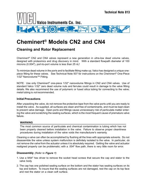
Technical Note 813<br />
<strong>Valco</strong> <strong>Instrument</strong>s Co. Inc.<br />
Cheminert ® Models <strong>CN2</strong> <strong>and</strong> <strong>CN4</strong><br />
Cleaning <strong>and</strong> Rotor Replacement<br />
Cheminert ® <strong>CN2</strong> <strong>and</strong> <strong>CN4</strong> valves represent a new generation in ultra-low dead volume valves,<br />
designed with proteomics <strong>and</strong> drug discovery in mind. With a st<strong>and</strong>ard flowpath diameter of 100<br />
microns (0.004"), port-to-port volume is less than 25 nL!<br />
To minimize dead volume in the ports <strong>and</strong> to facilitate fitting make-up, <strong>Valco</strong> has designed a unique onepiece<br />
fitting for these valves. See Technical Note 507 for instructions on the Cheminert ® One-Piece<br />
1/32" Nanovolume Fitting.<br />
NOTE: Use only Cheminert ® one-piece 1/32" nanovolume fittings in <strong>CN2</strong> <strong>and</strong> <strong>CN4</strong> valves. Use of<br />
st<strong>and</strong>ard <strong>Valco</strong> 1/32" zero dead volume nuts <strong>and</strong> ferrules could result in damage to the valve fitting<br />
details. We also recommend the use of polymeric or fused silica tubing for connecting to the valve;<br />
metal tubing is not recommended.<br />
Initial Precautions<br />
After unpacking the valve, do not remove the protective tape from the valve ports until you are ready to<br />
install the valve. As supplied, all surfaces are clean <strong>and</strong> free of contaminants, <strong>and</strong> must be kept clean<br />
to prevent valve damage. Open ports <strong>and</strong> fittings cause unnecessary risk of particulate matter entering<br />
the valve <strong>and</strong> scratching the sealing surfaces, which is the most frequent cause of premature valve<br />
failure.<br />
WARNING<br />
The most common source of particulate <strong>and</strong> chemical contamination is tubing which has not<br />
been properly cleaned before installation in the valve. Failure to observe proper cleanliness<br />
procedures during installation of the valve voids the manufacturer’s warranty.<br />
Cleaning a valve can often be accomplished by flushing all the lines with appropriate solvents. Do not<br />
disassemble the valve unless system malfunction is definitely isolated to the valve. In particular, do<br />
not remove the valve from the actuator unless it is absolutely required. Getting the valve <strong>and</strong> actuator<br />
realigned properly can be problematic; with a .004" flow path, there is very little room for error.<br />
Disassembly (Refer to Figure 1)<br />
1. Use a 9/64" hex driver to remove the socket head screws that secure the cap <strong>and</strong> stator to the<br />
valve body.<br />
2. The cap has one polished sealing surface on the bottom <strong>and</strong> the stator has sealing surfaces on its<br />
top <strong>and</strong> bottom. To insure that the sealing surfaces are not damaged, rest the cap on its top face<br />
<strong>and</strong> rest the stator on a clean soft surface.
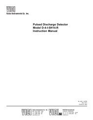
DRIVER<br />
ROTOR<br />
STATOR<br />
CAP<br />
Figure 1: Exploded view of the Model <strong>CN2</strong><br />
3. With your fingers or a small tool, gently pry the rotor away from the driver.<br />
4. Examine the rotor sealing surface for scratches. If you see any, the rotor must be replaced.<br />
5. Examine the stator <strong>and</strong> cap sealing surfaces. If scratches are visible between the ports, that part<br />
must be replaced or resurfaced. Call <strong>Valco</strong> for help in determining if resurfacing is feasible.<br />
6. Clean all the parts thoroughly with an appropriate solvent, taking care that no surfaces get scratched.<br />
(A common problem with HPLC is the formation of buffer crystals, which are usually water-soluble.)<br />
It is not necessary to dry the rotor.<br />
Reassembly<br />
1. Replace the rotor in the driver, making sure that the rotor sealing surface with its engraved flow<br />
passages is facing out. The tabs on the rotor have an asymmetrical pattern to prevent assembly<br />
with improper orientation.<br />
2. Replace the stator onto the body, making sure that the top side faces out. The two sides can be<br />
distinguished by the fact that the bottom has smaller holes <strong>and</strong> the top has larger conical holes.<br />
3. Replace the cap. Insert the two socket head screws <strong>and</strong> tighten them gently until both are snug.<br />
Do not overtighten them – the screws simply hold the assembly together <strong>and</strong> do not affect the<br />
sealing force, which is automatically set as the screws pull the cap <strong>and</strong> stator against the rotor.<br />
4. Test the valve by pressurizing the system. If it doesn’t hold pressure, the valve should be returned<br />
to <strong>Valco</strong> for repair.<br />
North America, South America, <strong>and</strong> Australia/Oceania contact:<br />
®<br />
<strong>Valco</strong> <strong>Instrument</strong>s Co. Inc.<br />
P.O. Box 55603<br />
Houston, TX 77255<br />
Sales: (800) 367-8424<br />
Tech: (713) 688-9345<br />
Fax: (713) 688-8106 valco@vici.com<br />
Europe, Asia, <strong>and</strong> Africa contact:<br />
®<br />
VICI AG International<br />
TN-813 Rev 3/05<br />
Parkstrasse 2<br />
CH-6214 Schenkon<br />
Switzerl<strong>and</strong><br />
Phone: +41 41 925 6200<br />
Fax: +41 41 925 6201 info@vici.ch<br />
Cheminert ® <strong>and</strong> VICI ® are registered trademarks of <strong>Valco</strong> <strong>Instrument</strong>s Co. Inc. <strong>and</strong> VICI AG