Manual SOLIVIA Gateway M1 G2 en.pdf - Delta Energy Systems
Manual SOLIVIA Gateway M1 G2 en.pdf - Delta Energy Systems
Manual SOLIVIA Gateway M1 G2 en.pdf - Delta Energy Systems
You also want an ePaper? Increase the reach of your titles
YUMPU automatically turns print PDFs into web optimized ePapers that Google loves.
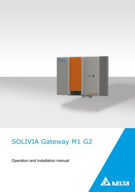
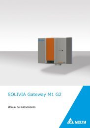
<strong>SOLIVIA</strong> <strong>Gateway</strong> <strong>M1</strong> <strong>G2</strong><br />
Operation and installation manual
The manual is subject to change.<br />
Please check our website at www.solar-inverter.com for the most up-to-date manual version.<br />
<strong>Delta</strong> <strong>Energy</strong> <strong>Systems</strong> (Germany) GmbH<br />
Tscheulinstraße 21<br />
79331 T<strong>en</strong>ing<strong>en</strong><br />
Germany<br />
© Copyright – <strong>Delta</strong> <strong>Energy</strong> <strong>Systems</strong> (Germany) GmbH - All rights reserved.<br />
This manual accompanies our equipm<strong>en</strong>t for use by the <strong>en</strong>d users.<br />
The technical instructions and illustrations contained in this manual are to be treated as confid<strong>en</strong>tial<br />
and no part may be reproduced without the prior writt<strong>en</strong> permission of <strong>Delta</strong> <strong>Energy</strong> <strong>Systems</strong><br />
Service <strong>en</strong>gineers and <strong>en</strong>d users may not divulge the information contained herein or use this<br />
manual for purposes other than those strictly connected with correct use of the equipm<strong>en</strong>t.<br />
All information and specifications are subject to change without notice.
Table of Cont<strong>en</strong>ts<br />
1 About this <strong>Manual</strong> 4<br />
1.1 Purpose of this <strong>Manual</strong> 4<br />
1.2 Warnings and Symbols 4<br />
2 Int<strong>en</strong>ded Use 5<br />
3 G<strong>en</strong>eral Safety Instructions 5<br />
4 Scope of Delivery 6<br />
5 Planning 6<br />
5.1 Items / Tools Required for Installation 6<br />
5.2 Further Requirem<strong>en</strong>ts 6<br />
6 Connector Positions 7<br />
7 Installation Procedure 8<br />
7.1 Registration 8<br />
7.2 Mounting 8<br />
7.2.1 Mounting on a DIN Rail 8<br />
7.2.2 Mounting Directly to the Wall 9<br />
7.3 RS485 Connection 9<br />
7.4 Ethernet Connection 9<br />
7.5 Connection of the Ripple Control Receivers 9<br />
7.6 Power Connection 11<br />
7.7 Installation Feedback 11<br />
8 LED Status 12<br />
9 Troubleshooting RS485 / Ethernet Communication 12<br />
10 Configuration through Web Server 12<br />
10.1 Access the Configuration Web Server 13<br />
10.2 First Log in 14<br />
10.3 Network Settings 14<br />
10.4 Connection Settings 15<br />
10.4.1 RS485 Bus Communication 16<br />
10.4.1.1 Wireless RS485 Modem 16<br />
10.4.2 <strong>Delta</strong> Database Connection 16<br />
10.4.3 Force RS485 Bus Scan 16<br />
10.4.3.1 List of Connected <strong>SOLIVIA</strong> Solar Inverters 16<br />
10.4.4 Force <strong>Gateway</strong> Reset 17<br />
10.4.5 Restart <strong>Gateway</strong> 17<br />
10.5 Digital Inputs 17<br />
10.5.1 Power Managem<strong>en</strong>t 18<br />
10.5.2 Power Factor Control 18<br />
10.6 Power Balancing 19<br />
10.6.1 Configuration 19<br />
10.6.1.1 Feature Activation 20<br />
10.6.1.2 Power Balancing Requested from the Public Grid Supplier 20<br />
10.6.1.3 Grid Assignm<strong>en</strong>t 20<br />
10.6.2 Balancing 21<br />
10.7 Inverter Information 21<br />
11 <strong>Delta</strong> Service Software 22<br />
12 Reset Button 22<br />
13 Product Specification 23<br />
14 Certificates 24<br />
EN<br />
Operation and installation manual <strong>SOLIVIA</strong> <strong>Gateway</strong> <strong>M1</strong> <strong>G2</strong><br />
3
1 About this <strong>Manual</strong><br />
Congratulations on the purchase of the <strong>SOLIVIA</strong> <strong>Gateway</strong> <strong>M1</strong> <strong>G2</strong>.<br />
These directions will help you become familiar with this product. Please observe the<br />
safety regulations of the individual countries. Careful handling of your product will contribute<br />
to its service life durability and reliability.<br />
1.1 Purpose of this <strong>Manual</strong><br />
This manual is part of the product and is only valid for the <strong>SOLIVIA</strong> <strong>Gateway</strong> <strong>M1</strong> <strong>G2</strong>.<br />
Keep this manual in a safe place.<br />
Read this manual carefully and follow the instructions giv<strong>en</strong> in this manual. This manual<br />
contains important information for installing and operating the gateway.<br />
Observe and follow the information for safe use (please refer to Chapter 3).<br />
Both the installer and the operator must have access to this manual and must be familiar<br />
with the safety instructions.<br />
1.2 Warnings and Symbols<br />
Here, you will find explanations for the warnings and symbols used in this<br />
manual:<br />
danger<br />
Indicates a hazardous situation. If not prev<strong>en</strong>ted, an<br />
accid<strong>en</strong>t will result in death or serious injury to humans.<br />
warning<br />
Indicates a hazardous situation. If not prev<strong>en</strong>ted, an accid<strong>en</strong>t<br />
could result in death or serious injury to humans.<br />
Caution<br />
Indicates a hazardous situation. If not prev<strong>en</strong>ted, an accid<strong>en</strong>t<br />
could result in moderate or minor injury to humans.<br />
NOTICE<br />
Indicates a hazardous situation, that could result in property<br />
damage.<br />
This symbol warns of the dangers of electric shock<br />
due to high electrical voltage.<br />
This symbol warns against a g<strong>en</strong>eral danger.<br />
4 Operation and installation manual <strong>SOLIVIA</strong> <strong>Gateway</strong> <strong>M1</strong> <strong>G2</strong>
In order to avoid damage to property or personal injury,<br />
only qualified, trained electricians may work on the equipm<strong>en</strong>t.<br />
The qualified electrician must familiarise himself/<br />
herself with this manual.<br />
EN<br />
Do not dispose of electrical appliances as unsorted<br />
municipal waste, use separate collection facilities.<br />
Contact your local governm<strong>en</strong>t for information regarding<br />
the collection systems available. If electrical appliances<br />
are disposed of in landfills or dumps, hazardous substances<br />
can leak into the groundwater and get into the<br />
food chain, damaging your health and well-being. Wh<strong>en</strong><br />
replacing old appliances with new once, the retailer is<br />
legally obligated to take back your old appliance for disposal<br />
at least for free of charge.<br />
2 Int<strong>en</strong>ded Use<br />
The <strong>SOLIVIA</strong> gateway is the interface betwe<strong>en</strong> your <strong>SOLIVIA</strong> inverter and the <strong>SOLIVIA</strong><br />
Monitor web portal. It transmits all relevant data from your <strong>SOLIVIA</strong> inverter (for example<br />
the supplied AC <strong>en</strong>ergy of the day, the actual AC power, some error bytes etc.) to<br />
the <strong>SOLIVIA</strong> Monitor web portal. It allows you continuous monitoring of your PV system<br />
from anywhere that you have internet access.<br />
The <strong>SOLIVIA</strong> gateway must be used indoors with IP20 <strong>en</strong>vironm<strong>en</strong>tal conditions.<br />
The <strong>SOLIVIA</strong> gateway must only be operated according to its int<strong>en</strong>ded use.<br />
3 G<strong>en</strong>eral Safety Instructions<br />
Please observe the safety regulations of the individual countries. Careful handling of<br />
your product will contribute to its service life durability and reliability. These are ess<strong>en</strong>tial<br />
pre-requisites for maximum yield from your product.<br />
• Inappropriate handling can lead to physical injury and material damage!<br />
• Do not remove warning labels that have be<strong>en</strong> attached to the <strong>SOLIVIA</strong> gateway<br />
by the manufacturer.<br />
• Observe all points in this installation and operation manual!<br />
• Repair work on the device may be carried out by the manufacturer only.<br />
• For a safe and normal operation of the <strong>SOLIVIA</strong> gateway, it is absolutely<br />
necessary that the gateway is installed and operated according to this manual<br />
(see IEC 62109-5.3.3).<br />
• <strong>Delta</strong> <strong>Energy</strong> <strong>Systems</strong> is not responsible for damage caused by failure to observe<br />
the operation and installation instructions in this manual.<br />
Operation and installation manual <strong>SOLIVIA</strong> <strong>Gateway</strong> <strong>M1</strong> <strong>G2</strong><br />
5
4 Scope of Delivery<br />
• <strong>SOLIVIA</strong> <strong>Gateway</strong> <strong>M1</strong> <strong>G2</strong><br />
• AC power plug (3 adapters for usage in differ<strong>en</strong>t countries)<br />
• Operation and installation manual<br />
• Label<br />
5 Planning<br />
5.1 Items / Tools Required for Installation<br />
Following items and tools are required for installation but are not included to the<br />
<strong>SOLIVIA</strong> gateway box. Please make sure to have them available before starting installation.<br />
• 1 standard twisted pair Ethernet cable<br />
NOTICE<br />
The Ethernet cable should meet or exceed the standard CAT5 and should not exceed<br />
a l<strong>en</strong>gth of 100 m. These standard twisted pair Ethernet cable can be purchased for<br />
your installation at many electronics and office supply retailers. The gateway requires<br />
a shielded cable STP, FTP, S/FTP or S/STP.<br />
•<br />
1 RS485 communication interface cable<br />
NOTICE<br />
The RS485 cable should meet the protection class IP65. We recomm<strong>en</strong>d using the<br />
RS485 cable from Harting (Part Number: 09 45 145 1560). Cable l<strong>en</strong>gths should not<br />
exceed 1200 m if Baud rate is 19200 (default value). The required cable quality is the<br />
same as for the Ethernet connection: at least shielded (STP, FTP, S/FTP or S/STP)<br />
CAT5 cable or better.<br />
• 2 screws are required to mount the gateway directly to the wall:<br />
»»<br />
Nominal diameter: 4 mm<br />
»»<br />
Maximum head diameter: 9 mm<br />
»»<br />
Maximum height of head: 3 mm<br />
• Screwdriver (if gateway should be mounted to the wall); size of the screwdriver<br />
dep<strong>en</strong>ds on used screws<br />
5.2 Further Requirem<strong>en</strong>ts<br />
NOTICE<br />
The <strong>SOLIVIA</strong> gateway must be installed only indoors according to protection class<br />
IP20.<br />
If more than one <strong>SOLIVIA</strong> solar inverter will be connected in a chain, <strong>en</strong>sure that<br />
each inverter has a unique ID assigned in the solar inverter user interface.<br />
6 Operation and installation manual <strong>SOLIVIA</strong> <strong>Gateway</strong> <strong>M1</strong> <strong>G2</strong>
• Please check the <strong>SOLIVIA</strong> solar inverter manual for instructions on how to select<br />
the inverter ID.<br />
• The gateway must have an AC power outlet within 2 meters of the gateway.<br />
EN<br />
NOTICE<br />
Please make sure, that DHCP is activated at your router, so that the IP address of<br />
your gateway is automatically found. If DHCP is disabled at your router the gateway<br />
uses the default IP configuration. For further information, please refer to Chapter 10.3<br />
6 Connector Positions<br />
STATUS<br />
Status LED<br />
GW<br />
RESET<br />
RS485<br />
EXT. CONTROL<br />
1 2 3 4 5 6 7 8 A B LAN INPUT<br />
5V<br />
CONNECTOR NAME DESCRIPTION<br />
RESET For detailed information, please refer to Chapter 7.8<br />
RS485<br />
Connection of your <strong>SOLIVIA</strong> inverter with the<br />
<strong>SOLIVIA</strong> gateway.<br />
EXT. CONTROL<br />
Ripple control receivers control the power managem<strong>en</strong>t (power<br />
limitation) and the power factor (cos ϕ).<br />
LAN<br />
Connection of your <strong>SOLIVIA</strong> gateway with an internet connected<br />
network point.<br />
INPUT 5V<br />
<strong>Gateway</strong> power supply connector.<br />
Operation and installation manual <strong>SOLIVIA</strong> <strong>Gateway</strong> <strong>M1</strong> <strong>G2</strong><br />
7
7 Installation Procedure<br />
7.1 Registration<br />
First register for a <strong>SOLIVIA</strong> Monitor user account on the web at: http://monitoring.solarinverter.com.<br />
After registering you will receive a confirmation email including a link to<br />
activate your user account. After the activation of your user account go to<br />
http://monitoring.solar-inverter.com and login to setup your PV installation at the monitoring<br />
portal (only the plant and the gateway are needed, the inverter will be created<br />
automatically). Complete the PV installation setup before installing the monitoring hardware.<br />
In this way, you can go to the web portal after the hardware installation and verify<br />
everything is working correctly.<br />
NOTICE<br />
At the install site, verify the internet connection is active by connecting a laptop to the<br />
internet connected network point and pointing a web browser to www.solar-inverter.<br />
com.<br />
7.2 Mounting<br />
Mount the <strong>SOLIVIA</strong> gateway with the appropriate AC power location specified in Chapter<br />
5.2. You have either the possibility to mount the <strong>SOLIVIA</strong> gateway on a DIN rail or<br />
directly to the wall.<br />
7.2.1 Mounting on a DIN Rail<br />
The gateway can be mounted on the following DIN Rails:<br />
• DIN Rail according to EN60715 TH35-15<br />
• DIN Rail according to EN60715 TH35-7.5<br />
The gateway should be installed horizontally with connectors on the bottom.<br />
To mount, snap the gateway on the DIN rail as shown in Figure 1:<br />
1. Pull the gateway's DIN rail latch OUT.<br />
2. Tilt the unit slightly upwards, hook the top <strong>en</strong>d onto the DIN rail and push downwards<br />
until stopped.<br />
3. Position the bottom front <strong>en</strong>d against the DIN rail until it has snapped onto the DIN<br />
rail.<br />
4. Push the gateway's DIN rail latch IN to lock.<br />
2<br />
1<br />
3<br />
4<br />
Figure 1: Mounting the gateway on a DIN rail<br />
2<br />
8 Operation and installation manual <strong>SOLIVIA</strong> <strong>Gateway</strong> <strong>M1</strong> <strong>G2</strong>
To dismount, pull the gateway's DIN rail latch OUT. Th<strong>en</strong>, tilt the bottom part of the unit<br />
out, push the unit up and pull out from the DIN rail.<br />
EN<br />
7.2.2 Mounting Directly to the Wall<br />
Mount the gateway with appropriate screws to the wall<br />
Use the 2 screws specified in Chapter 5.1 to mount the gateway with the DIN Rail to the<br />
wall. C<strong>en</strong>ter-to-c<strong>en</strong>ter distance betwe<strong>en</strong> the two boreholes is 70 mm.<br />
70 mm<br />
Figure 2: Mounting the gateway directly to the wall<br />
7.3 RS485 Connection<br />
Connect a standard CAT cable betwe<strong>en</strong> the RS485 connector on the <strong>SOLIVIA</strong> gateway<br />
and the RS485 connector on the <strong>SOLIVIA</strong> solar inverter. See step 1 in figure 4 below.<br />
7.4 Ethernet Connection<br />
Connect an Ethernet network cable betwe<strong>en</strong> the <strong>SOLIVIA</strong> gateway and the internet<br />
connected network point. See step 2 in figure 4.<br />
7.5 Connection of the Ripple Control Receivers<br />
You are able to connect the digital inputs to a giv<strong>en</strong> function. This concerns the control<br />
of the power the inverter feeds to the grid (power managem<strong>en</strong>t) and of the power factor<br />
(reactive power control).<br />
If your local public grid supplier requires a remote power derating capability, this can<br />
be implem<strong>en</strong>ted by using a ripple control receiver. Please connect the ripple control<br />
receiver as shown in figure 3. After the configuration as shown in Chapters 10.5<br />
and 10.6 the public grid supplier is capable to remotely limit the maximum power the<br />
<strong>SOLIVIA</strong> solar inverters provide to the public grid.<br />
Operation and installation manual <strong>SOLIVIA</strong> <strong>Gateway</strong> <strong>M1</strong> <strong>G2</strong><br />
9
The ripple control receiver that controls the power managem<strong>en</strong>t (power limitation) has<br />
to be connected to the inputs 1 to 4. The receiver that controls the power factor (cos<br />
phi) has to be connected to the inputs 5 to 8.<br />
After connection of the ripple control receiver(s) the gateway has to be configured in<br />
order to do the required control of the <strong>SOLIVIA</strong> solar inverters. For further information,<br />
please refer to Chapters 10.5 and 10.6.<br />
Of course it is also possible to connect only one ripple control receiver, i. e. the one that<br />
controls the power managem<strong>en</strong>t.<br />
Figure 3: Ripple control receivers circuit diagram<br />
NOTICE<br />
The cables connecting the <strong>SOLIVIA</strong> gateway with the ripple control receiver(s) should<br />
meet the following specifications:<br />
• Max. conductor cross-section: 0.5 mm 2 (AW<strong>G2</strong>0)<br />
• Min. conductor cross-section: 0.14 mm 2 (AW<strong>G2</strong>6)<br />
• Tight<strong>en</strong>ing torque: 0.12 – 0.15 Nm<br />
• Max. cable l<strong>en</strong>gth: 2 m<br />
10 Operation and installation manual <strong>SOLIVIA</strong> <strong>Gateway</strong> <strong>M1</strong> <strong>G2</strong>
7.6 Power Connection<br />
Connect the power source to the <strong>SOLIVIA</strong> gateway (Step 3 in figure 4) and check the<br />
<strong>SOLIVIA</strong> gateway LED. If the setup is correct, the Status LED will be solid gre<strong>en</strong> for<br />
approx. 5 seconds. For further information, please refer to Chapter 8.<br />
EN<br />
Verify that your setup is successful by going to the <strong>SOLIVIA</strong> Monitor web portal at:<br />
http://monitoring.solar-inverter.com and log in to view your PV system.<br />
STATUS<br />
3<br />
GW<br />
RESET<br />
RS485<br />
EXT. CONTROL<br />
1 2 3 4 5 6 7 8 A B LAN INPUT<br />
5V<br />
1<br />
2<br />
Internet<br />
RS485<br />
Figure 4: Connection diagram<br />
WARNING<br />
Risk of death or heavy injury due to dangerous voltage<br />
►►<br />
Repairs on defective cables should be done by qualified electricians<br />
only!<br />
►►<br />
Only recomm<strong>en</strong>ded and / or commercially available cables<br />
should be used.<br />
7.7 Installation Feedback<br />
NOTICE<br />
This function works only for <strong>SOLIVIA</strong> solar inverters of the 4th g<strong>en</strong>eration!<br />
Operation and installation manual <strong>SOLIVIA</strong> <strong>Gateway</strong> <strong>M1</strong> <strong>G2</strong><br />
11
After installation, the gateway checks the connection to the Ethernet and to the inverter.<br />
• If the Ethernet connection (connection to the internet resp. web portal) works, the<br />
gateway s<strong>en</strong>ds a message to the inverter. The following message appears on the<br />
display of the inverter: "Portal Connection ok".<br />
• If the Ethernet connection is not working, the following message appears on the<br />
display of the inverter: "No Portal Connection":<br />
Both messages will be displayed for 120 sec.<br />
If the message "No Portal Connection" appears on the display, please check the Ethernet<br />
connection of the gateway and your internet connection.<br />
If no message appears on the display, please check the RS485 connection betwe<strong>en</strong><br />
gateway and inverter and <strong>en</strong>sure that all inverters have unique RS485 bus IDs.<br />
8 LED Status<br />
The gateway has one single LED visible on top of the housing of the gateway. After<br />
power up, it immediately starts scanning for connected inverters. So the LED is constantly<br />
ON (no blinking) until the scan is finished.<br />
After that the LED change to one of the following behaviors:<br />
COLOR AND CONDITION<br />
Constantly ON (no blinking)<br />
Fast blinking (300 ms)<br />
Slow blinking (1 s)<br />
Hinking 200 ms on,<br />
1800 ms off<br />
Extremely fast blinking<br />
DESCRIPTION<br />
Neither Ethernet nor inverter connection.<br />
Ethernet connection but no inverter connection.<br />
No Ethernet connection but inverter connection.<br />
Ethernet as well as inverter connection is online.<br />
Indicates for one second that the reset button has be<strong>en</strong><br />
pressed.<br />
9 Troubleshooting RS485 / Ethernet Communication<br />
If one connection (Ethernet or RS485) works, try to exchange the cables. If now the<br />
other interface works it is very likely that one cable is brok<strong>en</strong>.<br />
10 Configuration through Web Server<br />
The HTTP-server implem<strong>en</strong>ts a browser interface allowing you to configure the gateway<br />
and to display several information. The features are:<br />
• Log in<br />
• Configuration<br />
• Display information about inverters<br />
12 Operation and installation manual <strong>SOLIVIA</strong> <strong>Gateway</strong> <strong>M1</strong> <strong>G2</strong>
10.1 Access the Configuration Web Server<br />
To access the configuration tool, you have to install the software program<br />
"IP Resolver" that you can download from our website: www.solar-inverter.com.<br />
NOTICE<br />
Please make sure, that your internet connection is active!<br />
EN<br />
Once installed, start the program by double-click.<br />
The following window will op<strong>en</strong>:<br />
In case that the IP address is not immediately found, click on the "rescan" button.<br />
Th<strong>en</strong>, double-click on the IP address in the "IP Resolver" to op<strong>en</strong> the web server.<br />
The log in window will op<strong>en</strong>:<br />
If your network do not work with DHCP, please proceed as follows:<br />
1. Configure your computer settings manually to 192.168.0.199<br />
2. Op<strong>en</strong> your web browser<br />
3. Insert IP http://192.168.0.200/<br />
4. Now go to Chapter 10.3 to see how you configure the IP of the <strong>SOLIVIA</strong> gateway.<br />
Operation and installation manual <strong>SOLIVIA</strong> <strong>Gateway</strong> <strong>M1</strong> <strong>G2</strong><br />
13
10.2 First Log in<br />
If you log in to the configuration web server for the first time, please <strong>en</strong>ter the following<br />
log in data:<br />
• Default Username: <strong>Delta</strong><br />
• Default Password: 000000<br />
Th<strong>en</strong>, click the "Log in" button.<br />
NOTICE<br />
If you leave the server untouched for more than five minutes, it is logged out automatically<br />
and any access will provide the log in page.<br />
As you log in for the first time, you will be asked to change your log in data for security<br />
reasons.<br />
The following window will automatically op<strong>en</strong>:<br />
• Change your log in data by following the instructions giv<strong>en</strong> and click on the<br />
"Submit" button.<br />
• After submitting your new data, the following message will confirm your changes:<br />
"Operation successfully completed!"<br />
10.3 Network Settings<br />
If your router is not supporting DHCP, you will have to <strong>en</strong>ter the IP address of your<br />
<strong>SOLIVIA</strong> gateway manually.<br />
Click on "Network Settings" on the left side to op<strong>en</strong> the following window where you<br />
can <strong>en</strong>ter your network parameters:<br />
14 Operation and installation manual <strong>SOLIVIA</strong> <strong>Gateway</strong> <strong>M1</strong> <strong>G2</strong>
EN<br />
NOTICE<br />
By default the gateway is configured to get its IP address from a DHCP server.<br />
To confirm your <strong>en</strong>tering, click the "Submit" button.<br />
10.4 Connection Settings<br />
Operation and installation manual <strong>SOLIVIA</strong> <strong>Gateway</strong> <strong>M1</strong> <strong>G2</strong><br />
15
10.4.1 RS485 Bus Communication<br />
Here you can set the baud rate of the gateway for the RS485 communication. The<br />
value should match the one of the inverter(s). The baud rate "19200" is set by default.<br />
NOTICE<br />
Please note, that the RS485 cable l<strong>en</strong>gths is dep<strong>en</strong>ding on the baud rate. Cable<br />
l<strong>en</strong>gths should not exceed 1200 m if baud rate is 19200 (default value).<br />
10.4.1.1 Wireless RS485 Modem<br />
If you are using a RS485 wireless modem, please check the box.<br />
10.4.2 <strong>Delta</strong> Database Connection<br />
Every few seconds, the gateway is retrieving data from the <strong>SOLIVIA</strong> solar inverters. The<br />
gateway stores these data and s<strong>en</strong>ds the average values to the database. Here you<br />
can define the intervals in minutes of how oft<strong>en</strong> the average values and parameters are<br />
s<strong>en</strong>t to the database. By default, 15 minutes is set.<br />
10.4.3 Force RS485 Bus Scan<br />
The gateway does not know the number and addresses of connected inverters in<br />
advance. It is assumed that each inverter connected to the bus already has its unique<br />
address in the range [1, 254]. Address 0 is not allowed and 255 is the value used for<br />
broadcasts.<br />
NOTICE<br />
Please check the <strong>SOLIVIA</strong> inverter user manual for instructions on how to select the<br />
inverter ID.<br />
Usually the list of inverters gets only longer. Every inverter that was once detected by<br />
the gateway will remain in this list. By pressing the "Start" button the list will be cancelled<br />
and the RS485 bus will be scanned for connected inverters.<br />
The gateway is designed to connect to a maximum of 32 devices.<br />
10.4.3.1 List of Connected <strong>SOLIVIA</strong> Solar Inverters<br />
At power-up, start-up and each day at about noon the gateway scans the RS485 bus<br />
for all connected <strong>SOLIVIA</strong> solar inverters.<br />
• Start from address 1 up to address 254. Address 0 is invalid and address 255 is<br />
the broadcast address.<br />
During the usual operation the gateway collects only the data of the inverters in the<br />
inverter list. If a new inverter is connected at e.g. 2:00 pm, this inverter will only be recognized<br />
after a new scan (latest the next day at about noon).<br />
16 Operation and installation manual <strong>SOLIVIA</strong> <strong>Gateway</strong> <strong>M1</strong> <strong>G2</strong>
10.4.4 Force <strong>Gateway</strong> Reset<br />
To reset the gateway to production settings press either the reset switch for more than<br />
5 seconds or click on the "Reset" button. After reset of the gateway, the default values<br />
shall become used again requiring a new configuration if needed.<br />
EN<br />
All the inverter data are cleared, the device is reset and a new RS485 bus<br />
scan starts, <strong>en</strong>ding with a flash store. The settings of Power Balancing,<br />
Power Managem<strong>en</strong>t, Power Factor Control, Baud-rate and s<strong>en</strong>d interval<br />
remain unchanged.<br />
10.4.5 Restart <strong>Gateway</strong><br />
By pressing the "Restart" button the gateway will be restarted. This restart has no<br />
impact on any configurations set before.<br />
10.5 Digital Inputs<br />
The <strong>SOLIVIA</strong> gateway gives a voltage to the output A and measures the inputs 1 to 8.<br />
In this way the <strong>SOLIVIA</strong> gateway can detect the state of the relays of the ripple control<br />
receivers. The information which relay shall control what parameter has to be communicated<br />
by the public grid supplier.<br />
Example: Information from the public grid supplier: If relay 2 is closed th<strong>en</strong> the power<br />
factor (cos ϕ) shall be set to 0.93 capacitive, if relays 1 and 2 are closed th<strong>en</strong> the power<br />
factor shall be set to 0.98 inductive.<br />
If the reactive power control receiver is connected to the <strong>SOLIVIA</strong> gateway as shown<br />
in figure 3 (Chapter 7.5) th<strong>en</strong> the “Power Factor Control” should be configured like in<br />
figure 5.<br />
Operation and installation manual <strong>SOLIVIA</strong> <strong>Gateway</strong> <strong>M1</strong> <strong>G2</strong><br />
17
10.5.1 Power Managem<strong>en</strong>t 1)<br />
There are four binary inputs that control the maximum power the inverter may feed into<br />
the grid.<br />
Power managem<strong>en</strong>t is at 100 % for all relay state combination except 60 % for relay 1,<br />
30 % for relay 2, and 0 % for relay 3 (default settings).<br />
10.5.2 Power Factor Control 1)<br />
The power factor configuration page allows the definition of 15 values for the cos φ,<br />
either inductive or capacitive. If all inputs are inactive the cos φ is 1.00.<br />
The values are <strong>en</strong>tered in the form 0.xx, e.g. 0.95 and a checkbox decides whether it is<br />
leading curr<strong>en</strong>t (capacitive) or not.<br />
NOTICE<br />
Please remember to save the configurations by pressing the “Submit” button.<br />
1) This chapter is only relevant for countries, in which your public grid supplier requires a power reduction<br />
(power managem<strong>en</strong>t), power factor control and/or power balancing.<br />
18 Operation and installation manual <strong>SOLIVIA</strong> <strong>Gateway</strong> <strong>M1</strong> <strong>G2</strong>
EN<br />
Figure 5: Power factor control configuration page<br />
10.6 Power Balancing 1)<br />
The German Low Voltage Directive VDE-AR-N-4105 requires a symmetrical power feed<br />
into all three lines of the AC grid. The allowed phase unbalance in Germany is 4.6<br />
kVA. Other countries may have the same or similar requirem<strong>en</strong>ts. Please observe the<br />
specific regulations of your country.<br />
If the power injected into the public grid is not ev<strong>en</strong>ly shared over the three phases, the<br />
gateway is able to balance this unsymmetry.<br />
10.6.1 Configuration<br />
Following configurations can be set:<br />
• Activate or deactivate the balancing<br />
• Set the maximum allowed unbalance<br />
• Assign the single-phase inverters to a line (L1, L2, L3)<br />
1) This chapter is only relevant for countries, in which your public grid supplier requires a power reduction<br />
(power managem<strong>en</strong>t), power factor control and/or power balancing.<br />
Operation and installation manual <strong>SOLIVIA</strong> <strong>Gateway</strong> <strong>M1</strong> <strong>G2</strong><br />
19
10.6.1.1 Feature Activation<br />
By default the feature is off. For countries without restrictions nothing has to be done.<br />
10.6.1.2 Power Balancing Requested from the Public Grid Supplier<br />
The default value is 4.6 kVA due to the German regulation. This value can be changed<br />
to other values without restriction.<br />
10.6.1.3 Grid Assignm<strong>en</strong>t<br />
For each inverter found during the bus scan, you can choose to which line (L1, L2 or<br />
L3) the device is connected.<br />
NOTICE<br />
Please note that the gateway web server will show you a warning if the sum of the<br />
nominal powers on the three phases differs by more than the maximum unbalanced<br />
load. Ev<strong>en</strong> with this warning the balancing works. However this warning is a strong<br />
indication that the mapping of the inverters to the public grid phases should be<br />
reviewed carefully!<br />
There is no possibility to check the right mapping of the inverters to<br />
the phase except the electrician verifies the cabling of each inverter.<br />
Thus the installer should be reminded to put att<strong>en</strong>tion to this issue.<br />
20 Operation and installation manual <strong>SOLIVIA</strong> <strong>Gateway</strong> <strong>M1</strong> <strong>G2</strong>
10.6.2 Balancing<br />
The gateway balances the power per phase after every data polling cycle:<br />
• The gateway requests every inverter for the curr<strong>en</strong>t data.<br />
• After the last inverter of the bus has s<strong>en</strong>t its information, the gateway calcuculates<br />
the power of each line.<br />
• The gateway calculates the curr<strong>en</strong>t unbalance.<br />
• The gateway selects the inverters to be power reduced.<br />
• The gateway calculates the reduction factor that is needed to balance the power.<br />
• The gateway s<strong>en</strong>ds the power control command to the specific inverters.<br />
EN<br />
The gateway reduces the power as little as possible. This means that the power balancing<br />
is not reducing the unbalance to 0 kVA, a reduction is only needed until the adjusted<br />
unbalance limit is adhered.<br />
10.7 Inverter Information<br />
Here you can find the complete list of all <strong>SOLIVIA</strong> solar inverters that were once<br />
detected by the gateway. The list contains the following information:<br />
• Connection of the solar inverter<br />
»»<br />
yes = connected<br />
»»<br />
no = not connected<br />
• Inverter type<br />
• Serial # of the <strong>SOLIVIA</strong> solar inverter<br />
• ID (of the solar inverter)<br />
Beside these information, you can read out the states of the portal connection and of<br />
the gateway, the MAC and IP address, the firmware (FW) version as well as the count<br />
of the flash saves.<br />
By clicking a serial number you get detailed information about an inverter.<br />
Operation and installation manual <strong>SOLIVIA</strong> <strong>Gateway</strong> <strong>M1</strong> <strong>G2</strong><br />
21
11 <strong>Delta</strong> Service Software<br />
The <strong>Delta</strong> Service Software <strong>en</strong>ables the installer to adapt settings, realize firmware<br />
upgrades and other updates besides supporting him in detecting error sources, like e.<br />
g. over- or undervoltage -without any need to op<strong>en</strong> the inverter. The memory from every<br />
inverter can be stored and readout with the software in order to facilitate maint<strong>en</strong>ance<br />
and on-site service. Detailed information of every inverter can be monitored and if necessary<br />
adapted.<br />
The <strong>SOLIVIA</strong> gateway replaces the service software kit, that consists out of a <strong>Delta</strong><br />
RS485 special cable and a USB to RS485 converter. Therefore, beside the gateway<br />
and the software itself, which can be downloaded from our website free of charge, no<br />
further equipm<strong>en</strong>t nor tools are necessary.<br />
Proceed as follows:<br />
1. Connect a RS485 cable betwe<strong>en</strong> the RS485 connector on the <strong>SOLIVIA</strong> gateway<br />
and the RS485 connector on the <strong>SOLIVIA</strong> inverter.<br />
2. Connect an Ethernet network cable betwe<strong>en</strong> the <strong>SOLIVIA</strong> gateway and the<br />
internet ready network port.<br />
3. Donwload the software from our website free of charge.<br />
4. Start the service software program.<br />
NOTICE<br />
Please make sure, that your internet connection is active!<br />
For further information about the <strong>SOLIVIA</strong> service software, please refer to our website<br />
at www.solar-inverter.com.<br />
12 Reset Button<br />
The reset button offers two differ<strong>en</strong>t functionalities. Please also refer to Chapter 10 for<br />
further information on the below m<strong>en</strong>tioned configuration parameters.<br />
1. Keep the reset button pressed > 5 seconds and < 20 seconds<br />
»»<br />
LED blinks very fast for one second to indicate the reset has be<strong>en</strong> recognized.<br />
»»<br />
Does a soft reset of the configuration parameters.<br />
»»<br />
Baud rate, interval time, power managem<strong>en</strong>t, and unbalanced settings are not<br />
changed (except that “use unbalanced” is switched off). The other parameters<br />
are reset to default:<br />
üü<br />
DHCP active<br />
üü<br />
Proxy not active<br />
üü<br />
Wireless RS485 modem not active<br />
üü<br />
Unbalanced correction not active<br />
üü<br />
Default IPs in subnet 192.168.0.200<br />
üü<br />
Proxy IP 0.0.0.0<br />
üü<br />
Default password (000000) and username (<strong>Delta</strong>)<br />
»»<br />
Inverter list is cleared<br />
22 Operation and installation manual <strong>SOLIVIA</strong> <strong>Gateway</strong> <strong>M1</strong> <strong>G2</strong>
2. Keep the reset button pressed > 20 seconds<br />
»»<br />
LED blinks very fast for one second to indicate the reset has be<strong>en</strong> recognized.<br />
»»<br />
All Parameters are reset to their default (factory settings), i.e.:<br />
üü<br />
All network settings<br />
üü<br />
Baud rate 19200<br />
üü<br />
Interval 15 min<br />
üü<br />
Power managem<strong>en</strong>t is at 100 % for all relay state combination except<br />
60 % for relay 1, 30 % for relay 2, and 0% for relay 3<br />
üü<br />
Unbalanced load = 4.6 kVA<br />
üü<br />
Clear all unbalanced configuration<br />
üü<br />
Clear all power factor (cos phi) configuration<br />
»»<br />
This reset might require the reconfiguration from your public grid supplier.<br />
EN<br />
13 Product Specification<br />
RS485 INTERFACE<br />
Max. in/output<br />
voltage<br />
± 5 V<br />
Output curr<strong>en</strong>t ≤ 250 mA<br />
Input curr<strong>en</strong>t<br />
≤ 42 mA<br />
ETHERNET INTERFACE (LAN)<br />
Max. in/output<br />
voltage<br />
± 3 V<br />
Output curr<strong>en</strong>t ≤ 20 mA<br />
Input curr<strong>en</strong>t<br />
≤ 20 mA<br />
POWER SUPPLY (INPUT 5 V DC)<br />
Max. input voltage<br />
Min. input voltage<br />
Max. input curr<strong>en</strong>t<br />
Nom. input curr<strong>en</strong>t<br />
+8 V<br />
+4 V<br />
≤ 600 mA<br />
(3 W @ 5V)<br />
approx. 185 mA<br />
(1 W @ 5 V)<br />
RIPPLE CONTROL RECEIVER<br />
INTERFACE 1)<br />
Input voltage<br />
(ports 1 to 8)<br />
≤ 3.5 V<br />
Input curr<strong>en</strong>t<br />
(ports 1 to 8)<br />
≤ 1 mA<br />
Output voltage<br />
(ports A+B)<br />
≤ 3.5 V<br />
Output curr<strong>en</strong>t<br />
(ports A+B)<br />
≤ 20 mA<br />
AMBIENT CONDITIONS<br />
Operating<br />
temperature range<br />
0 °C to 40 °C<br />
Storage<br />
temperature range<br />
-40 °C to 80 °C<br />
Relative humidity 0 % to 90 %<br />
POWER SUPPLY UNIT 2)<br />
PSU voltage<br />
4 V to 8 V<br />
range<br />
Max. output power<br />
Max. output<br />
curr<strong>en</strong>t<br />
≥ 3 W (LPS certified)<br />
≥ 600 mA (LPS certified)<br />
1) EXT. CONTROL<br />
2) Use only the power supply adapter supplied with and suited for the <strong>SOLIVIA</strong> gateway<br />
Operation and installation manual <strong>SOLIVIA</strong> <strong>Gateway</strong> <strong>M1</strong> <strong>G2</strong><br />
23
14 Certificates<br />
This Class (B) digital apparatus complies with Canadian ICES-003.<br />
Cet appareil numérique de la classe (B) est conforme à la norme NMB-003 du Canada.<br />
This device complies with Part 15 of the FCC Rules. Operation is subject to the following<br />
two conditions: (1) this device may not cause harmful interfer<strong>en</strong>ce, and (2) this<br />
device must accept any interfer<strong>en</strong>ce received, including interfer<strong>en</strong>ce that may cause<br />
undesired operation.<br />
<br />
<br />
<br />
<br />
<br />
<br />
<br />
<br />
<br />
<br />
<br />
<br />
<br />
<br />
<br />
<br />
<br />
<br />
<br />
<br />
<br />
<br />
<br />
<br />
<br />
<br />
<br />
<br />
<br />
<br />
<br />
<br />
<br />
<br />
<br />
<br />
<br />
24 Operation and installation manual <strong>SOLIVIA</strong> <strong>Gateway</strong> <strong>M1</strong> <strong>G2</strong>
Sing Etac Services Pty Ltd<br />
ABN 941339000008<br />
33 Mackeller Av<strong>en</strong>ue Wheelers Hill Vic 3150<br />
Australia<br />
Phone +61 3 95451418 Fax + 61 3 95451418<br />
EN<br />
Ref #: 12CTICK001<br />
C-Tick Mark Conformity Declaration<br />
For the following equipm<strong>en</strong>t:<br />
Basic <strong>Gateway</strong><br />
(Model Name)<br />
<strong>SOLIVIA</strong> GW WEB MONITOR GATEWAY <strong>M1</strong> <strong>G2</strong><br />
(Model Designation)<br />
Herewith is confirmed to comply with the requirem<strong>en</strong>ts set out in the regulation to Electromagnetic<br />
Compatibility. For the evaluation regarding the electromagnetic compatibility, the following standards<br />
were applied:<br />
AS/NZS CISPR 22 & CISPR 11<br />
The following manufacturer is responsible for this declaration:<br />
Company name: <strong>Delta</strong> Electronics (Thailand) Public Co., Ltd<br />
Address: 909 Soi 9, Moo 4, Bangpoo Industrial Estate (E.P.Z) Pattana 1 Rd., Tambol Phraksa,<br />
Amphur Muang, Samutprakarn 10280, THAILAND<br />
The following importer is responsible for this declaration:<br />
Company name: Sing Etac Services Pty Ltd<br />
Address: 33 Mackeller Av<strong>en</strong>ue Wheelers Hill Vic 3150, Australia<br />
Person responsible for making this declaration:<br />
Christina Ch<strong>en</strong> Sok Kian<br />
(Name)<br />
Director<br />
(Position/Title)<br />
March 9, 2012<br />
(Date)<br />
(Legal Signature)<br />
Operation and installation manual <strong>SOLIVIA</strong> <strong>Gateway</strong> <strong>M1</strong> <strong>G2</strong><br />
25
26 Operation and installation manual <strong>SOLIVIA</strong> <strong>Gateway</strong> <strong>M1</strong> <strong>G2</strong>
EN<br />
Operation and installation manual <strong>SOLIVIA</strong> <strong>Gateway</strong> <strong>M1</strong> <strong>G2</strong><br />
27
28 Operation and installation manual <strong>SOLIVIA</strong> <strong>Gateway</strong> <strong>M1</strong> <strong>G2</strong>
EN<br />
Operation and installation manual <strong>SOLIVIA</strong> <strong>Gateway</strong> <strong>M1</strong> <strong>G2</strong><br />
29
SUPPORT - EUROPE<br />
Austria<br />
service.oesterreich@solar-inverter.com<br />
0800 291 512 (Free Call)<br />
Belgium<br />
support.belgium@solar-inverter.com<br />
0800 711 35 (Free Call)<br />
Bulgaria<br />
support.bulgaria@solar-inverter.com<br />
+421 42 4661 333<br />
Czech Republic<br />
podpora.czechia@solar-inverter.com<br />
800 143 047 (Free Call)<br />
D<strong>en</strong>mark<br />
support.danmark@solar-inverter.com<br />
8025 0986 (Free Call)<br />
France<br />
support.france@solar-inverter.com<br />
0800 919 816 (Free Call)<br />
Germany<br />
service.deutschland@solar-inverter.com<br />
0800 800 9323 (Free Call)<br />
Greece<br />
support.greece@solar-inverter.com<br />
+49 7641 455 549<br />
Israel<br />
support.israel@solar-inverter.com<br />
+49 7641 455 549<br />
Italy<br />
supporto.italia@solar-inverter.com<br />
800 787 920 (Free Call)<br />
The Netherlands<br />
ondersteuning.nederland@solar-inverter.com<br />
0800 022 1104 (Free Call)<br />
Portugal<br />
suporte.portugal@solar-inverter.com<br />
+49 7641 455 549<br />
Slovakia<br />
podpora.slov<strong>en</strong>sko@solar-inverter.com<br />
0800 005 193 (Free Call)<br />
Slov<strong>en</strong>ia<br />
podpora.slov<strong>en</strong>ija@solar-inverter.com<br />
+421 42 4661 333<br />
Spain<br />
soporto.espana@solar-inverter.com<br />
900 958 300 (Free Call)<br />
Switzerland<br />
support.switzerland@solar-inverter.com<br />
0800 838 173 (Free Call)<br />
United Kingdom<br />
support.uk@solar-inverter.com<br />
0800 051 4281 (Free Call)<br />
Other European countries<br />
support.europe@solar-inverter.com<br />
+49 7641 455 549<br />
www.solar-inverter.com<br />
04 December 2012


