Computational fluid dynamics - Flygt
Computational fluid dynamics - Flygt
Computational fluid dynamics - Flygt

You also want an ePaper? Increase the reach of your titles
YUMPU automatically turns print PDFs into web optimized ePapers that Google loves.
Engineering & Expertise<br />
Hydraulic modeling<br />
<strong>Computational</strong> <strong>fluid</strong> <strong>dynamics</strong>
Engineering & Expertise<br />
Total solution engineering<br />
increases operational efficiency<br />
Introduction<br />
Understanding <strong>fluid</strong> flow inside hydraulic<br />
structures is a critical factor in the design<br />
of pump stations. But intuition and experience<br />
are not always enough to develop<br />
optimized solutions or to communicate<br />
with customers about the advantages of<br />
the proposed design. <strong>Computational</strong> Fluid<br />
Dynamics, or CFD, is an excellent modeling<br />
tool that can be used in the design process to<br />
simulate various design alternatives, identify<br />
flow problems, develop solutions and<br />
evaluate operating strategies. As such, the<br />
CFD is a cost-effective alternative to physical<br />
modeling.<br />
In this brochure, we will show how we use<br />
CFD to solve engineering problems related<br />
to pump station design for specific customer<br />
projects. But we also use CFD in developing<br />
generic designs for different types of pump<br />
stations or process applications, and last but<br />
not least, we use CFD in the design of pumps<br />
and mixers.<br />
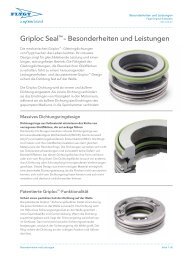
Achieving lowest total cost of ownership<br />
When providing pumping solutions, <strong>Flygt</strong> prefers to<br />
take the total cost of ownership into consideration.<br />
Unplanned<br />
Investment<br />
Operational<br />
• Investment costs<br />
Costs associated with design, excavation, civil work,<br />
product purchases, installation and commissioning.<br />
• Operational costs<br />
Over time, energy usage and maintenance costs<br />
are often the major contributors to the overall costs<br />
along with the cost of labor required to run the<br />
system.<br />
• Unplanned costs<br />
When things go wrong, such as pump failures stemming<br />
from problematic station design, costs can<br />
sky rocket. Unexpected downtime can cause sewer<br />
backups, overflows, basement flooding and untreated<br />
effluent. On top of that, you have to repair<br />
pumps and take corrective measures regarding the<br />
station design.<br />
Theoretical analysis<br />
Products<br />
Physical tests<br />
Engineering & Expertise<br />
Thanks to our engineering expertise, we can lower<br />
your total cost of ownership. We can analyze your<br />
system using state-of-the-art computational programs.<br />
We can test your pump station using scale<br />
models if required. We can also provide you with<br />
reference installations that are similar to your project.<br />
All of this together with our premium products<br />
provides you with an optimized design.<br />
Reference installations<br />
Engineering & Expertise<br />
2
What is CFD?<br />
Introduction<br />
CFD is a sophisticated computer-based design and<br />
analysis technique. Using CFD, we can build a computational<br />
model that represents a system or a device<br />
that we want to study. We then apply the general <strong>fluid</strong><br />
flow equations to predict the flow field and related<br />
physical phenomena. In general, CFD gives us the<br />
power to simulate turbulent <strong>fluid</strong> flow, heat and mass<br />
transfer, multiphase flows, chemical reactions, <strong>fluid</strong>structure<br />
interaction and acoustics.<br />
The first CFD codes were developed for the aerospace<br />
industry in the 1960s. Since then, the use of<br />
CFD has spread to all industries that deal with <strong>fluid</strong><br />
mechanics directly or indirectly. Today, other major<br />
industrial users of CFD include automotive, power,<br />
turbomachinery, chemical, environmental and many<br />
other industries.<br />
Almost all CFD codes are based on the Navier-<br />
Stokes equations, which arise from the application of<br />
Newton’s second law to <strong>fluid</strong> flows. These are general<br />
governing equations for any type of <strong>fluid</strong> motion,<br />
but they can only be solved analytically for laminar<br />
flow or for a few very simple geometries in turbulent<br />
flow. Since most engineering problems involve turbulent<br />
flow and fairly complex geometries, the flow<br />
equations have to be solved numerically.<br />
the computational cells has to be smaller than the<br />
length scale of the smallest turbulent eddies for an<br />
exact solution, which in most cases is impractical.<br />
For this reason, the CFD codes use time-averaged<br />
equations such as the Reynolds-averaged Navier-<br />
Stokes equations (RANS) when modeling turbulent<br />
flows. With this approach, the turbulence is modeled<br />
for sub-grid scales. There are different turbulence<br />
models available depending on the flow<br />
characteristics.<br />
The exact numerical solution of the Navier-Stokes<br />
equations for turbulent flow is extremely demanding<br />
because of the wide range of time and length<br />
scales involved in turbulent flow. In fact, the size of<br />
Achieving lowest total cost of ownership<br />
When designing a pump station, our goal is to help our<br />
customers to achieve the lowest total cost of ownership.<br />
We always try to make the pump station as small<br />
as feasibly possible to minimize the investment cost.<br />
We analyze operating conditions and advise the best<br />
operating strategies to minimize the energy costs. We<br />
also address possible issues with sediment or floating<br />
debris to eliminate, or at least reduce, the costs related<br />
to cleaning and maintenance. CFD analysis is often a<br />
critical factor in achieving these objectives, as we explain<br />
throughout this brochure.<br />
3
Introduction<br />
The process of CFD analysis<br />
CFD analysis is a fairly complex task that typically<br />
involves three stages: preprocessing, solving and<br />
postprocessing.<br />
Preprocessing is building a computational flow<br />
model:<br />
• Formulation of the flow problem for CFD analysis<br />
• Modeling the geometry: Building or importing<br />
CAD geometry and adapting it for CFD<br />
• Generation of a computational mesh: Subdividing<br />
the <strong>fluid</strong> volume into a grid that typically consists<br />
of millions of discrete cells<br />
• Defining <strong>fluid</strong> material properties, initial conditions<br />
and boundary conditions for the model<br />
Defining physical bounds.<br />
P<br />
Solving the flow equations may be the most time-consuming<br />
stage because the flow equations are being<br />
solved iteratively in all grid cells. To speed up the solution,<br />
calculations are done in parallel mode on multicore<br />
computer clusters:<br />
• Selecting appropriate flow equations and numerical<br />
schemes<br />
• Solving the flow equations until predetermined<br />
convergence criteria are met, typically thousands<br />
of iterations<br />
• Compiling and exporting results for<br />
postprocessing<br />
Mesh generation.<br />
P<br />
Postprocessing is the final step in CFD analysis. It involves<br />
organization, interpretation and presentation<br />
of the results. The following steps are involved:<br />
• Production of CFD images and animations showing<br />
the flow field and other relevant variables<br />
• Calculation of integral parameters<br />
• Analysis and interpretation of the results<br />
• Reporting<br />
It is not unusual that the insight gained from the first<br />
round of CFD analysis prompts another round aimed<br />
at making improvements to the model. Depending<br />
on the nature of changes, the whole process, or at<br />
least most of its steps, has to be repeated for each<br />
round.<br />
Visualization of flow and vorticity.<br />
P<br />
4
Interpreting the CFD results<br />
For a novice, CFD is synonymous with colorful<br />
graphics. It is true that simulation results are often<br />
presented by many colorful plots, but they should<br />
not be taken as abstract art; all lines and colors<br />
have specific meanings. The most commonly used<br />
types of plots in our field are those showing velocity<br />
and pressure. In a three-dimensional flow domain,<br />
the flow field is characterized by a three-dimensional<br />
vector field. Since there is no simple way of<br />
showing such a vector field, several types of plots<br />
are used.<br />
One type of plot uses streamlines, which are curves<br />
that are tangent to velocity vectors. They can be<br />
colored by velocity magnitude so they effectively<br />
convey both direction and magnitude of velocity in<br />
a three-dimensional space.<br />
We initially used CFD for developing turbomachinery:<br />
pump impellers, volutes, mixers and other<br />
hydraulic parts. Currently we can model complete<br />
pumps with rotating impellers or more complex<br />
systems such as pump stations, mixing or aeration<br />
tanks. We promote the use of CFD in designing<br />
pump stations for customer projects for any<br />
non-standard configuration or any large pump station<br />
if the risks involved outweigh the costs of CFD<br />
modeling.<br />
At <strong>Flygt</strong>, we use three different top-ranked CFD<br />
codes: ANSYS Fluent, ANSYS CFX, and CFD++. We<br />
also use other state-of-the-art software for meshing<br />
and postprocessing. To ensure short turnaround<br />
time, most of calculations are done on our own<br />
computer clusters.<br />
Another way of showing the velocity field is to use<br />
cross sections through the flow domain overlaid<br />
with contour maps of velocity magnitude or with velocity<br />
vectors. Usually, several cross-sectional plots<br />
are required to show the three-dimensional characteristics<br />
of the flow.<br />
Besides graphical results, integral parameters<br />
such as flow rates or pressure forces can also be<br />
calculated.<br />
CFD at <strong>Flygt</strong><br />
We pioneered the use of CFD in the pump industry<br />
in the 1980s. All our CFD engineers have solid background<br />
in <strong>fluid</strong> mechanics and vast experience with<br />
real-world hydraulics. This type of expertise is essential<br />
in making accurate and reliable simulations.<br />
It helps throughout the entire modeling process,<br />
from selecting the limits of the model, through developing<br />
computational meshes, using correct numerical<br />
techniques to correctly interpreting the results.<br />
The expertise also comes in handy in finding<br />
effective solutions to any encountered problems.<br />
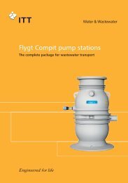
CFD model of a complete pump with a rotating propeller<br />
(pump housing removed for clarity); colors indicate pressure on<br />
the blades and other internal surfaces.<br />
5
Design conditions<br />
Adverse hydraulic<br />
phenomena<br />
To ensure the expected pump performance and<br />
long service intervals, it is important to design the<br />
pump sump to prevent adverse flow conditions.<br />
Excessive pre-swirl<br />
Pre-swirl changes the flow conditions at the pump<br />
inlet, which results in a change in the relative impeller<br />
speed. This, in turn, causes a change in pump<br />
performance, which can lead to overloading the<br />
motor or reduced pump performance. Excessive<br />
pre-swirl can also result in bearing wear and cavitation<br />
across the impeller area. Pre-swirl usually<br />
large variation results in an uneven load on the impeller<br />
and bearings. Unsteady flow causes the load<br />
on the impeller to fluctuate, which leads to noise, vibration,<br />
bearing loads and increased risk of fatigue<br />
failures.<br />
Vortices<br />
Unlike excessive pre-swirl, vortices appear locally<br />
with higher intensity and are a major hindrance<br />
to proper pump operation, resulting in cavitation,<br />
uneven load, noise and vibration. There are several<br />
different types of vortices.<br />
The most commonly known type is the free surface<br />
vortex, which can have varying degrees of intensity<br />
– from weak surface vortices to fully developed vortices<br />
with a continuous air core that extends from<br />
the surface into the pump.<br />
A non-uniform approach inflow leads to pre-swirl.<br />
originates from an asymmetric velocity distribution<br />
in the approach channel, which evolves into a<br />
pre-swirl at the pump inlet. The Hydraulic Institute<br />
recommends a pre-swirl angle that does not exceed<br />
5°, calculated from the ratio between the tangential<br />
velocity and the axial velocity.<br />
Less well known, but just as common is the vortex<br />
that originates under the surface from the sump<br />
bottom, walls or between two pumps, and extends<br />
to the pump inlet. This type of vortex can achieve<br />
high rotational speed with high subpressures and<br />
cavitations.<br />
Uneven velocity distribution at the pump intake<br />
Uneven velocity distribution can result from different<br />
types of phenomena and disturbances. While<br />
some unevenness in velocity distribution is inevitable<br />
and does not harm the pump, variations that<br />
are greater than 10% at the pump intake can have<br />
severe consequences and should be avoided. A<br />
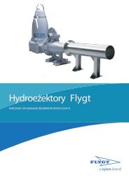
Strong surface vortex.<br />
Strong submerged vortex.<br />
Uneven velocity into the pump inlet.<br />
A surface vortex enters a transparent pump in a test rig.<br />
6
Optimizing pump station<br />
design through CFD<br />
Case studies<br />
<strong>Computational</strong> modeling gives us a good understanding<br />
of pump station hydraulics. With this insight,<br />
we can evaluate intake conditions in pump<br />
stations, either existing or new ones. We can also<br />
develop improvements or design alternatives. The<br />
required time and cost for CFD analysis are usually<br />
much less than those required for physical modeling.<br />
We can therefore model more pump stations more<br />
frequently than when restricted to physical modeling<br />
alone.<br />
In general, the use of CFD has allowed us to generate<br />
smarter solutions and more optimized pump station<br />
Case study 1: New station design<br />
designs than before. Ultimately, these improvements<br />
benefit our customers through lower cost<br />
and reduced risk related to pump station construction<br />
and operation.<br />
We do CFD modeling at the design stage rather<br />
than after the pump stations are in operation. This<br />
way, we solve problems before they occur.<br />
For existing stations, CFD helps us troubleshoot by<br />
revealing existing flow conditions and identifying<br />
probable causes of problems. Improved understanding<br />
leads to effective solutions, better design<br />
and smarter operating strategies for the pump<br />
station.<br />
Challenge<br />
This intake station to a treatment plant will be<br />
equipped with 23 large centrifugal <strong>Flygt</strong> pumps.<br />
Each pump delivers approximately 1 m³/s (16,000<br />
US gpm). In the original design, all pumps are located<br />
on the same level. The flow enters the pump<br />
station via 12 narrow ports. These ports create very<br />
high velocity jet streams, which result in a very nonuniform<br />
approach flow to the pumps, excessive preswirl<br />
and consequently unreliable installation.<br />
| Solution<br />
The alternative design proposed by <strong>Flygt</strong> has a baffle<br />
wall just downstream of the inlet ports. A well dimensioned<br />
baffle wall will dissipate the energy from the<br />
jet streams and distribute the incoming flow across<br />
the entire width of the basin. Another change in our<br />
design is to locate the pumps on two different levels,<br />
which reduces the interference between the pumps.<br />
CFD simulations of the new design confirm nearly<br />
uniform approach flow to the pumps with no adverse<br />
hydraulic phenomena.<br />
Original design.<br />
New two-level design.<br />
Original design simulated with CFD.<br />
New design simulated with CFD.<br />
7
Case studies<br />
Case study 2: Design optimization<br />
Challenge<br />
This stormwater pump station was designed with<br />
sharply diverging sidewalls giving rise to non-uniform<br />
flow distribution with a strong jet in the middle<br />
of the sump. This would in turn cause rough pump<br />
operation, vibrations and possibly cavitation.<br />
| Solution<br />
The solution proposed by us was to capture the<br />
flow with dividing walls before it could develop into<br />
a jet and uniformly distributed the flow among the<br />
pumps.<br />
CFD simulation of original design.<br />
CFD simulation of modified design.<br />
Case study 3: Trouble shooting<br />
Challenge<br />
| Solution<br />
This stormwater pump<br />
station was troubled by<br />
a high-energy vortex,<br />
which developed in the<br />
sump due to a sharp turn<br />
at the intake into the station.<br />
This vortex penetrated<br />
all the way into<br />
the pump causing noise,<br />
vibration and increased<br />
power consumption. The<br />
vortex was clearly visible<br />
as shown in the photo<br />
below.<br />
Problem – vortex.<br />
A <strong>Flygt</strong> Formed<br />
Suction Intake<br />
device solved this<br />
problem. It has a<br />
sloped ceiling that<br />
funnels the flow at<br />
the same time as it<br />
blocks surface air<br />
intake. In addition,<br />
it has a straightening<br />
vane that eliminates<br />
the swirl.<br />
Solution – formed suction intake.<br />
Original CFD simulation showing vortex.<br />
CFD simulation of modified design with uniform flow.<br />
8
Proven worldwide<br />
Reference installations<br />
<strong>Flygt</strong> has supplied pumps to thousands of pump stations<br />
around the world where our engineers were<br />
involved in the design and commissioning. This experience<br />
is one of the foundations of our engineering<br />
expertise. Another one is hydraulic modeling of over<br />
a hundred pump stations around the world. On top<br />
of these, CFD has brought a new dimension to building<br />
this expertise. In addition to quickly pinpointing<br />
problems and solutions, the insight we are gaining<br />
from CFD has enormous educational impact that we<br />
pass on to our customers around the world.<br />
The two examples below illustrate how non-standard<br />
pump station designs could be successfully developed<br />
using CFD modeling.<br />
United States: Large capacity circular wet well<br />
Challenge<br />
Very deep, large capacity and limited footprint:<br />
these are common demands by customers for their<br />
pump stations designs. Recently, two such pump<br />
stations were needed in the US.<br />
Solution<br />
The best solution from an investment and operational<br />
perspective in cases such as these is often to install<br />
submersible pumps in a circular wet well design. <strong>Flygt</strong><br />
pioneered the installation of submersible pumps in<br />
large capacity circular wet wells and has gained a lot<br />
of experience in this area from model testing and<br />
proven installations.<br />
For these two stations, a similar design was used in<br />
both applications. One was more than 50 m (160 ft)<br />
deep and 20 m (64 ft) in diameter. It had 12 pumps<br />
with a capacity of 4.4 m³/s (70,000 US gpm) each.<br />
We applied previous experience together with a<br />
CFD model to achieve safe and reliable inflow conditions<br />
for the pumps.<br />
Australia: Desalination plant<br />
Challenge<br />
One of Australia’s largest cities was running short<br />
of fresh water and needed a major expansion of its<br />
desalination facility. One hurdle was to transfer the<br />
seawater to the plant. A new pump station would<br />
be required. The challenge was the large number<br />
of pumps, 16 in all, required to do the job. This<br />
number is beyond the scope of handbook designs.<br />
Solution<br />
The consulting engineer for the city commissioned<br />
<strong>Flygt</strong> to help develop a problem-free design using<br />
CFD. The CFD study highlighted potential problems<br />
with sedimentation and was instrumental in<br />
developing appropriate solutions.<br />
9
Services AND support<br />
Engineering & Expertise<br />
To ensure reliable and highly efficient operation,<br />
we offer comprehensive support and service for<br />
pump station design, system analysis, installation,<br />
commissioning, operation and maintenance.<br />
Design tools<br />
When you design pump stations, we can offer<br />
advanced engineering tools to generate sump<br />
designs. Our design recommendations give you<br />
essential information regarding dimensions and<br />
layout. In short, we assist you every step of the<br />
way to make sure you optimize performance and<br />
achieve energy-efficient operations.<br />
Theoretical analysis<br />
<strong>Computational</strong> <strong>fluid</strong> <strong>dynamics</strong> (CFD) can provide far<br />
more detailed information about the flow field in a<br />
fraction of the time required to get the same information<br />
through physical hydraulic scale model testing.<br />
Using CFD in combination with computer-aided<br />
design (CAD) tools, it is possible to obtain a more<br />
efficient method of numerical simulation for pump<br />
station design.<br />
To obtain a reliable, energy-efficient pumping<br />
system, it is important to analyze all modes of operation.<br />
To analyze the transient effects at pump<br />
start and stop with respect to flow and head as<br />
well as the electrical parameters such as current<br />
and torque, it is also important to have an accurate<br />
mathematical description of the pump and motor,<br />
which is gained, in part, from extensive testing in<br />
our laboratories.<br />
10
Physical testing<br />
Physical hydraulic scale model testing can provide<br />
reliable, cost-effective solutions to complex hydraulic<br />
problems. This is particularly true for pump stations<br />
in which the geometry departs from recommended<br />
standards or where no prior experience with the<br />
application exists. Scale model testing can also be<br />
employed to identify solutions for existing installations<br />
and has proven to be a far less expensive way<br />
to determine the viability of possible solutions than<br />
through trial and error at full scale.<br />
Reference installations<br />
We have conducted system analysis and designed<br />
pump stations for thousands of installations around<br />
the world. Engineering expertise and years of experience<br />
gained from the design and operation of these<br />
installations have been a critical success factor when<br />
analyzing, testing and commissioning new pump<br />
installations.<br />
When our standard design recommendations are<br />
not met, we can assist in determining the need for<br />
physical testing as well as planning and arranging<br />
the testing and evaluating the results.<br />
Theoretical analysis<br />
Products<br />
Physical tests<br />
Reference installations<br />
Engineering & Expertise<br />
Model test photos courtesy of Hydrotec Consultants Ltd.<br />
11
1) The tissue in plants that brings water upward from the roots<br />
2) A leading global water technology company<br />
We’re 12,000 people unified in a common purpose: creating innovative solutions<br />
to meet our world’s water needs. Developing new technologies that will improve<br />
the way water is used, conserved, and re-used in the future is central to our work.<br />
We move, treat, analyze, and return water to the environment, and we help people<br />
use water efficiently, in their homes, buildings, factories and farms. In more than<br />
150 countries, we have strong, long-standing relationships with customers who<br />
know us for our powerful combination of leading product brands and applications<br />
expertise, backed by a legacy of innovation.<br />
1200 . Hydraulic Modeling . 1 . Master . 1 . 20120419<br />
For more information on how Xylem can help you, go to xyleminc.com.<br />
<strong>Flygt</strong> is a brand of Xylem. For the latest<br />
version of this document and more<br />
information about <strong>Flygt</strong> products visit<br />
www.flygt.com