
You also want an ePaper? Increase the reach of your titles
YUMPU automatically turns print PDFs into web optimized ePapers that Google loves.
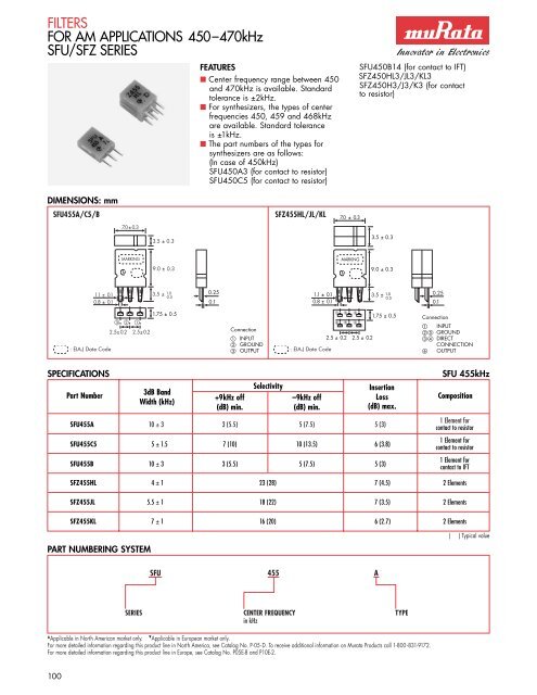
FILTERS<br />
FOR AM APPLICATIONS 450–470kHz<br />
SFU/SFZ SERIES<br />
FEATURES<br />
■ Center frequency range between 450<br />
and 470kHz is available. Standard<br />
tolerance is ±2kHz.<br />
■ For synthesizers, the types of center<br />
frequencies 450, 459 and 468kHz<br />
are available. Standard tolerance<br />
is ±1kHz.<br />
■ The part numbers of the types for<br />
synthesizers are as follows:<br />
(In case of 450kHz)<br />
SFU450A3 (for contact to resistor)<br />
SFU450C5 (for contact to resistor)<br />
SFU450B14 (for contact to IFT)<br />
SFZ450HL3/JL3/KL3<br />
SFZ450H3/J3/K3 (for contact<br />
to resistor)<br />
DIMENSIONS: mm<br />
SFU455A/C5/B<br />
SFZ455HL/JL/KL<br />
7.0±0.3<br />
7.0±0.3<br />
3.5 ± 0.3<br />
3.5 ± 0.3<br />
MARKING<br />
MARKING<br />
M<br />
9.0 ± 0.3<br />
M<br />
9.0 ± 0.3<br />
1.1 ± 0.1<br />
0.8 ± 0.1<br />
3.5 ± 1.0<br />
0.5<br />
0.25<br />
0.1<br />
1.1 ± 0.1<br />
0.8 ± 0.1<br />
3.5 ± 1.0<br />
0.5<br />
0.25<br />
0.1<br />
<br />
1.75 ± 0.5<br />
<br />
<br />
2.5±0.2 2.5± 0.2<br />
Connection<br />
INPUT<br />
2.5 ± 0.2<br />
GROUND<br />
: EIA-J Date Code OUTPUT<br />
: EIA-J Date Code<br />
<br />
1.75 ± 0.5<br />
<br />
2.5 ± 0.2<br />
Connection<br />
INPUT<br />
GROUND<br />
DIRECT<br />
CONNECTION<br />
OUTPUT<br />
SPECIFICATIONS<br />
Part Number<br />
3dB Band<br />
Width (kHz)<br />
SFU 455kHz<br />
Selectivity<br />
Insertion<br />
+9kHz off –9kHz off Loss Composition<br />
(dB) min. (dB) min. (dB) max.<br />
SFU455A 10 ± 3 3 (5.5) 5 (7.5) 5 (3)<br />
SFU455C5 5 ± 1.5 7 (10) 10 (13.5) 6 (3.8)<br />
SFU455B 10 ± 3 3 (5.5) 5 (7.5) 5 (3)<br />
1 Element for<br />
contact to resistor<br />
1 Element for<br />
contact to resistor<br />
1 Element for<br />
contact to IFT<br />
SFZ455HL 4 ± 1 23 (28) 7 (4.5) 2 Elements<br />
SFZ455JL 5.5 ± 1 18 (22) 7 (3.5) 2 Elements<br />
SFZ455KL 7 ± 1 16 (20) 6 (2.7) 2 Elements<br />
PART NUMBERING SYSTEM<br />
( ) Typical value<br />
SFU 455 A<br />
SERIES CENTER FREQUENCY TYPE<br />
in kHz<br />
<br />
Applicable in North American market only. <br />
Applicable in European market only.<br />
For more detailed information regarding this product line in North America, see Catalog No. P-05-D. To receive additional information on <strong>Murata</strong> Products call 1-800 -831-9172.<br />
For more detailed information regarding this product line in Europe, see Catalog No. P05E-8 and P10E-2.<br />
100
FILTERS<br />
FOR AM APPLICATIONS–SIGNAL DETECTION<br />
BFU/SFZ SERIES<br />
FEATURES<br />
■ fa – fr: Difference between the antiresonant<br />
frequency and the resonant<br />
frequency<br />
■ Most suitable for IC Station Detectors<br />
(SD) such as the LA 1135 (by Sanyo)<br />
DIMENSIONS: mm<br />
BFU Series<br />
SFZ Series <br />
0.8 ± 0.1<br />
1.1 ± 0.1<br />
7.0 ± 0.3<br />
MARKING<br />
M<br />
3.5 ± 0.3<br />
9.0 ± 0.3<br />
3.5 ± 0.5<br />
1.5 max.<br />
1.1 ± 0.1<br />
0.8 ± 0.1<br />
7.0 ± 0.3<br />
MARKING<br />
M<br />
4.0 ± 0.5<br />
9.0 ± 0.3<br />
3.5 +1.0<br />
–0.5<br />
0.25<br />
0.1<br />
0.25 ± 0.05<br />
0.1 ± 0.05<br />
5.0 ± 0.2<br />
1.75 ± 0.5<br />
: EIA-J Date Code NO DIRECTIVITY<br />
: EIA-J Date Code<br />
<br />
<br />
2.5 ± 0.2<br />
1.75 ± 0.5<br />
3.5 ± 0.5<br />
Connection<br />
INPUT<br />
GROUND<br />
DIRECT<br />
CONNECTION<br />
OUTPUT<br />
FILTERS<br />
SPECIFICATIONS<br />
Part Resonant fa – fr Resonant Capacitance<br />
Number Frequency (kHz) (kHz) Resistance () max. (pF)<br />
BFU450K3 450 ± 1 27.5 ± 4.5 30 (10) 550 ± 20%<br />
BFU450C 450 ± 1 14 ± 2 20 (10) 360 ± 20%<br />
BFU450C4N 450 ± 0.8 9 ± 2 30 (12) 360 ± 20%<br />
Part Center 3dB Bandwidth<br />
Number Frequency (kHz) (kHz)<br />
SFZ450C3N 450 ± 1 2.5 ± 1<br />
PART NUMBERING SYSTEM<br />
f 0 – 9kHz<br />
(30dB)<br />
Selectivity<br />
f 0 + 9kHz<br />
(24dB)<br />
Application<br />
IF Signal Detection<br />
( ) Typical value<br />
BFU 450 C<br />
SERIES CENTER FREQUENCY TYPE<br />
in kHz<br />
<br />
Applicable in North American market only. <br />
Applicable in European market only.<br />
For more detailed information regarding this product line in North America, see Catalog No. P-05-D. To receive additional information on <strong>Murata</strong> Products call 1-800 -831-9172.<br />
For more detailed information regarding this product line in Europe, see Catalog No. P10E-2.<br />
101
FILTERS<br />
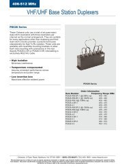
FOR AM APPLICATIONS, MINIATURE<br />
PFS/PFB/PFWCC SERIES<br />
FEATURES<br />
■ Center frequency is available<br />
between 450 and 470kHz. Standard<br />
tolerance is ±2kHz.<br />
■ For synthesizers, the types of center<br />
frequencies 450, 459 and 468kHz<br />
are available. Standard tolerance<br />
is ±1kHz.<br />
■ PFWCC Series is mountable by<br />
automatic placers. (“–TC” is added<br />
to the part number for tape and reel.<br />
ex. PFWCC450JR-TC)<br />
DIMENSIONS: mm<br />
PFB455JR PFS450A* PFWCC450J3*<br />
IN<br />
Input Mark<br />
GND<br />
7.0±0.3<br />
MARKING<br />
M<br />
2.4 ± 0.3<br />
4.8 ± 0.3<br />
0.4 ± 0.1 0.4 ± 0.1<br />
0.6 ± 0.1<br />
7.0±0.3<br />
MARKING<br />
M<br />
2.4 ± 0.3<br />
4.8 ± 0.3<br />
0.4 ± 0.1 0.4 ± 0.1<br />
1.5 ± 0.5<br />
0.6 ± 0.1<br />
5.0 ± 1.0<br />
0.18 ± 0.05<br />
0.7 ± 0.3<br />
0.18 ± 0.05<br />
<br />
0.7 ± 0.3<br />
<br />
0.5 ± 0.5<br />
0.3<br />
0.3 ± 0.25<br />
2.5 ± 0.2 2.5 ± 0.2<br />
2.5 ± 0.2 2.5 ± 0.2<br />
Connection<br />
Connection<br />
INPUT<br />
INPUT<br />
GROUND<br />
GROUND<br />
: EIA-J Date Code OUTPUT<br />
: EIA-J Date Code<br />
OUTPUT<br />
5.0 ± 0.3<br />
1.0 ± 0.2<br />
1.0 ± 0.2<br />
M<br />
55J<br />
OUT GND<br />
5.7 ± 0.3<br />
1.2 ± 0.2 1.2 ± 0.2<br />
<br />
<br />
<br />
<br />
4.0 ± 0.2<br />
: EIA-J Date Code<br />
1.5 ± 0.2<br />
1.5 ± 0.2<br />
Connection<br />
INPUT<br />
OUTPUT<br />
GROUND<br />
GROUND<br />
*Available on tape<br />
SPECIFICATIONS<br />
Part Number<br />
3dB Band<br />
Width (kHz)<br />
Selectivity<br />
Insertion<br />
+9kHz off Loss Composition<br />
(dB) min.<br />
(dB) max.<br />
PFB455JR 5.5 ± 1.5 17 (23) 6 (3) 2 Elements<br />
PFS450A 4.5 ± 1.5 8 5 1 Element, Leaded<br />
PFWCC450J3 5.5 ± 1.5 17 (23) 6 (3) 2 Elements, SMD<br />
PART NUMBERING SYSTEM<br />
( ) Typical value<br />
PFB 455 JR<br />
SERIES FREQUENCY TYPE<br />
in kHz<br />
<br />
Applicable in North American market only. <br />
Applicable in European market only.<br />
For more detailed information regarding this product line in North America, see Catalog No. P-05-D. To receive additional information on <strong>Murata</strong> Products call 1-800 -831-9172.<br />
For more detailed information regarding this product line in Europe, see Catalog No. P10E-2.<br />
102
FILTERS<br />
FOR AM APPLICATIONS–HIGHLY SELECTIVE<br />
CFWS/SFPS SERIES<br />
For synthesizers, the available center<br />
frequencies are 450, 459 and 468kHz.<br />
Standard tolerance is ±1kHz.<br />
Because of excellent shape factor, wideband<br />
width and high selectivity, this<br />
series is the most suitable to car radios<br />
and all-band radios.<br />
■ Operating temperature range:<br />
–20°C to +80°C<br />
Storage temperature range:<br />
–40°C to +85°C<br />
FEATURES<br />
■ Low profile, high selectivity<br />
■ Easily mountable on any PC board.<br />
DIMENSIONS: mm<br />
SFPS450H<br />
8.0±0.3<br />
CFWS450HT<br />
11.0± 0.5<br />
MARKING<br />
M<br />
7.0 ±0.3<br />
MARKING<br />
M<br />
7.0±0.5<br />
1.5 max. 7.0±0.3<br />
0.3±0.1<br />
7.5±0.5<br />
1.5 max.<br />
0.8±0.1<br />
0.8±0.1<br />
0.15±0.05<br />
3.0±0.3<br />
0.15<br />
3.5<br />
±0.5<br />
2.7±0.3<br />
1.2±0.5<br />
0.6±0.1<br />
2.9±0.3 2.9±0.3 2.6±0.3 1.2±0.5<br />
0.6±0.1<br />
<br />
4.2±0.3<br />
1.35±0.3 <br />
<br />
Connection<br />
3.3±0.5<br />
INPUT<br />
2.3±0.5 2.3±0.3<br />
GROUND<br />
: EIA-J Date Code OUTPUT<br />
: EIA-J Date Code<br />
4.3± 0.3<br />
Connection<br />
INPUT<br />
GROUND<br />
OUTPUT<br />
FILTERS<br />
SPECIFICATIONS<br />
Part Number<br />
6dB Bandwidth<br />
(kHz) min.<br />
CFWS450 kHz/SFPS450kHz<br />
Selectivity Insertion Matching<br />
±9kHz off Loss Impedance Composition<br />
(dB) min. (dB) max. (k)<br />
SFPS450H<br />
±3.0<br />
40 (60) 6 (1.5) 2.0<br />
4 Elements<br />
(±4.0) Ladder Type<br />
CFWS450HT<br />
±3.0<br />
50 (75) 6 (2.0) 2.0<br />
6 Elements<br />
(±4.0) Ladder Type<br />
( ) Typical value<br />
PART NUMBERING SYSTEM<br />
CFWS 450 H<br />
SERIES CENTER FREQUENCY BANDWIDTH<br />
in kHz<br />
Available as standard through authorized <strong>Murata</strong> Electronics Distributors. <br />
Applicable in North American market only. <br />
Applicable in European market only.<br />
For more detailed information regarding this product line in North America, see Catalog No. P-05-D. To receive additional information on <strong>Murata</strong> Products call 1-800 -831-9172.<br />
For more detailed information regarding this product line in Europe, see Catalog No. P10E-2.<br />
103
FILTERS<br />
FOR AM APPLICATIONS<br />
SFGCG, SFPC, CFUCG 455kHz<br />
Along with the development of the AM<br />
chip filter, IF filters for AM/FM radios<br />
have also been made smaller, thinner<br />
and in a chip configuration for surface<br />
mounting. This is one more example<br />
of <strong>Murata</strong> Electronics’ leadership in<br />
converting conventional electronic<br />
components to chip technology.<br />
FEATURES<br />
■ The filters are mountable by<br />
automatic placers.<br />
■ The filters can be reflow soldered<br />
and withstand washing.<br />
■ They are slim, at only 4.0mm<br />
maximum thickness, and have a<br />
small mounting area enabling<br />
flexible PCB design. (5.0mm<br />
maximum thickness for SFPC).<br />
■ The bandwidth ranges from 35kHz<br />
to 6kHz.<br />
■ Operating temperature range:<br />
–20°C to +80°C<br />
Storage temperature range:<br />
–40°C to +85°C<br />
■ For reflow soldering<br />
■ Also available in 450kHz<br />
center frequency<br />
DIMENSIONS: mm<br />
CFUCG/SFGCG<br />
SFPC<br />
6.5<br />
CO.5<br />
1.0 ± 0.1 1.0 ± 0.1 1.2 ± 0.1<br />
Sealing<br />
7.5 <br />
max. <br />
4.0<br />
max.<br />
7.5<br />
7.0<br />
50D<br />
M<br />
3.0<br />
8.4<br />
max.<br />
<br />
5.0 max.<br />
1.0<br />
4.0 1.0<br />
3.0<br />
6.0<br />
1.5 1.5 Sealing<br />
0.9 ± 0.1<br />
1.5 1.5 1.6<br />
2.0 2.0<br />
Sealing<br />
INPUT<br />
GROUND<br />
OUTPUT<br />
: EIA-J Date Code<br />
INPUT<br />
GROUND<br />
OUTPUT<br />
SPECIFICATIONS<br />
Part<br />
Number<br />
*Note: For safety purposes, connect the output of filters to the IF amplifier through a DC blocking capacitor. Avoid applying a direct current to the output of ceramic filters.<br />
CFUCG/SFGCG/SFPC SERIES<br />
_____________________________________________________________<br />
Center Frequency Bandwidth (Total) Ripple (max.) *Insertion Stop Band ___________________<br />
Group Delay (max.) Source<br />
Loss Atten. (min.)<br />
and Load<br />
Nom. Tol. 3dB (min.) 6dB (min.) 40dB (max.) Point of<br />
Point of<br />
(kHz) ± (kHz) (kHz) (kHz) (kHz)<br />
dB<br />
(max.) at ± 100kHz S<br />
Impedance<br />
Measure<br />
dB dB<br />
Measure<br />
()<br />
CFUCG455D-TC 455 1.5 — 10 20 2.0 ±7 4 27 — — 1500<br />
CFUCG455E-TC 455 1.5 — 15 30 1.5 ±5 6 27 — — 1500<br />
CFUCG455F-TC 455 1.5 — 12 25 1.5 ±4 6 27 — — 1500<br />
CFUCG455G-TC 455 1 — 9 20 1.5 ±3 6 25 — — 1500<br />
CFUCG455FX-TC 455 1.5 — 12 30 1 ±4 6 27 25 ±4 1500<br />
CFUCG455GX-TC 455 1 — 9 25 1 ±3 6 25 25 ±3 1500<br />
CFUCG455HX-TC 455 1 — 6 20 1 ±2 7 25 25 ±2 1500<br />
SFGCG455AX2-TC 455 — 28 — 70 1 ±10 5 25 15 ±10 1000<br />
SFGCG455BX-TC 455 1.5 — 30 70 1 ±10 5 25 15 ±10 1000<br />
SFGCG455CX-TC 455 1.5 — 25 60 1 ±8 6 25 15 ±8 1000<br />
SFGCG455DX-TC 455 1 — 20 50 1 ±7 7 23 20 ±7 1500<br />
SFGCG455EX-TC 455 1 — 15 40 1 ±5 8 23 20 ±5 1500<br />
SFPC455E-TC 455 1.5 — 15 30 1.5 ±5 6 27 — — 1500<br />
SFPC455F-TC 455 1.5 — 12 25 1.5 ±4 6 27 — — 1500<br />
SFPC455G-TC 455 1 — 9 20 1.5 ±3 6 25 — — 1500<br />
SFPC455H-TC 455 1 — 6 — 1.5 ±2 6 35 — — 2000<br />
SFGCG455AX-TC 455 2 — 35 80 1 ±10 4 25 15 ±10 1000<br />
PART NUMBERING SYSTEM<br />
CFUCG 455 E – TC<br />
SERIES CENTER FREQUENCY BANDWIDTH TAPE CARRIER<br />
in kHz<br />
<br />
Applicable in North American market only. <br />
Applicable in European market only.<br />
For more detailed information regarding this product line in North America, see Catalog No. P-05-D. To receive additional information on <strong>Murata</strong> Products call 1-800 -831-9172.<br />
For more detailed information regarding this product line in Europe, see Catalog No. P05E-8.<br />
104
FILTERS<br />
FOR FM APPLICATIONS–LOW LOSS, HIGHLY SELECTIVE,<br />
MINIATURE–SFE MA/MS/MJ/MH 10.7MHz<br />
DIMENSIONS: mm<br />
The standard SFE 10.7 line of ceramic<br />
filters are extremely reliable devices<br />
that exhibit excellent waveform<br />
symmetry. These filters have traditionally<br />
found wide application in FM receiver<br />
technology.<br />
FEATURES<br />
■ These miniature filters have high<br />
mechanical strength.<br />
■ Low loss, favorable waveform<br />
symmetry, and high selectivity<br />
■ Various band widths are available for<br />
STANDARD SERIES A10 SERIES C10 SERIES TEST CIRCUIT<br />
Low Loss<br />
Low Profile<br />
applications in wide to narrow bands.<br />
■ Small dispersion and stable<br />
characteristics.<br />
■ Change in center frequency is<br />
typically within ±30ppm/°C at<br />
–20 ~ +80°C.<br />
■ High reliability<br />
7.0<br />
7.0<br />
8.0<br />
E10.7S<br />
M<br />
<br />
7.0<br />
5.0<br />
E10.7S<br />
M<br />
<br />
7.0<br />
5.0<br />
10.7SC<br />
M<br />
6.0 max.<br />
5.0<br />
R 1 <br />
R 2<br />
Rg=50<br />
S.S.G.<br />
C<br />
RF<br />
Voltmeter<br />
2.5 2.5<br />
2.5 2.5<br />
2.5 2.5<br />
3 ± 1 3 ± 1 3 ± 1<br />
<br />
Rg + R 1 = R 2 = 330 ± 5%<br />
C = 10pF<br />
(including stray capacitance and input<br />
capacitance of RF Voltmeter)<br />
INPUT<br />
GROUND<br />
OUTPUT<br />
SPECIFICATIONS<br />
Part Number<br />
SFE A10/B10/C10 SERIES<br />
3dB Bandwidth 20dB Bandwidth Ripple Insertion Loss Spurious (9~12MHz)<br />
(kHz) (kHz) max. (dB) max. (dB) max. (dB) min.<br />
SFE10.7MA5-A 280 ± 50 650 (520) 1 6 (4) 30 (43)<br />
FM-IF SFE10.7MS2-A 230 ± 50 600 (420) 1 6 (4) 40 (45)<br />
SFE10.7MS3-A 180 ± 40 520 (380) 1 7 (4.5) 40 (45)<br />
• Input/output impedance: 330 ( ) Typical value<br />
SFE10.7MA5A10-A 280 ± 50 590 (480) 1 2.5 ± 2.0 30 (42)<br />
A10 Series<br />
SFE10.7MS2A10-A 230 ± 40 520 (410) 1 3.0 ± 2.0 35 (42)<br />
SFE10.7MS3A10-A 180 ± 40 470 (370) 1 3.5 ± 1.5 35 (42)<br />
SFE10.7MJA10-A 150 ± 40 360 (300) 1 4.5 ± 2.0 35 (42)<br />
• Input/output impedance: 330 • Low loss and high selectivity. ( ) Typical value<br />
SFE10.7MA5B10-A 280 ± 50 650 1 3.0 ± 2.0 45<br />
B10 Series SFE10.7MS2B10-A 230 ± 50 570 1 3.0 ± 2.0 45<br />
SFE10.7MS3B10-A 180 ± 40 520 1 5.0 ± 2.0 45<br />
• Input/output impedance: 330 • High attenuation type<br />
SFE10.7MA5C10-A 280 ± 50 650 (540) 1 3.0 ± 2.0 30 (47)<br />
SFE10.7MS2C10-A 230 ± 50 570 (470) 1 3.0 ± 2.0 40 (49)<br />
C10 Series SFE10.7MS3C10-A 180 ± 40 470 (360) 1 3.5 ± 2.0 35 (47)<br />
SFE10.7MJC10-A 150 ± 40 360 (300) 1 4.5 ± 2.0 35 (42)<br />
SFE10.7MHC10-A 110 ± 30 350 ( 260) 1 7.0 ± 2.0 30 (38)<br />
• Input/output impedance: 330 • Most suitable for a thin type and low profile set. • The performance is the same as that of conventional types. ( ) Typical value<br />
FILTERS<br />
PART NUMBERING SYSTEM<br />
SFE 10.7M A5A10 H – A<br />
SERIES CENTER FREQUENCY RATING, CHARACTERISTICS TOLERANCE OF RANK OF CENTER<br />
in MHz CENTER FREQUENCY FREQUENCY<br />
±30kHz = Blank<br />
±25kHz = H<br />
±20kHz = K<br />
<br />
Applicable in North American market only. <br />
Applicable in European market only.<br />
For more detailed information regarding this product line in North America, see Catalog No. P-05-D. To receive additional information on <strong>Murata</strong> Products call 1-800 -831-9172.<br />
For more detailed information regarding this product line in Europe, see Catalog No. P61E-4.<br />
105
FILTERS<br />
FOR FM APPLICATIONS–HIGHLY SELECTIVE G.D.T. FLAT TYPE<br />
SFE MX/MA8/ML 10.7MHz<br />
The SFE 10.7MX/MA8/ML lines of ceramic<br />
filters were designed to minimize the<br />
dispersion of amplitude and phase<br />
characteristics within the pass band. Because<br />
the excellent G.D.T. characteristics of these<br />
filters insure signal integrity, they are<br />
recommended for use in applications ranging<br />
from high grade stereo receivers to digital<br />
transmission systems.<br />
FEATURES<br />
■ Little dispersion of amplitude characteristics<br />
and phase characteristics (G.D.T.<br />
characteristics)<br />
■ The SFE 10.7 MX Series has G.D.T.<br />
characteristics and is useful for obtaining<br />
DIMENSIONS<br />
MX SERIES MA8 SERIES ML SERIES TEST CIRCUIT<br />
Low Distortion High Selectivity, Low Loss Selectivity<br />
low distortion. SFE 10.7 ML Series, in these<br />
ceramic filters, being in harmony with<br />
flatness of G.D.T., roundness of the<br />
amplitude and selectivity characteristics,<br />
therefore, these ceramic filters are suitable<br />
to high-grade stereo tuners. Even if<br />
mismatching condition, they can keep little<br />
distortion because of low Qm of ceramic<br />
material. The SFE 10.7 MA8 Series is<br />
based on SFE 10.7 MA5/MS2/MS3, and<br />
it obtains high selectivity with low loss.<br />
There is little dispersion of amplitude and<br />
G.D.T. characteristics, and low distortion<br />
rate can be obtained.<br />
■ All products are inspected for symmetry<br />
and roundness of amplitude<br />
9.0 max.<br />
7.0 ± 2<br />
7.0 ± 2<br />
<br />
E10.7X<br />
M<br />
11.0 max.<br />
E10.7A<br />
M<br />
7.0 ± 2<br />
E10.7L<br />
M<br />
7.0 ± 2<br />
R 1<br />
R 2<br />
Rg=50<br />
S.S.G.<br />
C<br />
RF<br />
Voltmeter<br />
5.0 ± 1<br />
5.0 ± 1<br />
2.5 2.5<br />
2.5 2.5<br />
<br />
<br />
3 ± 1 3 ± 1<br />
5.0 ± 1<br />
2.5<br />
<br />
2.5<br />
3 ± 1<br />
: EIA-J Date Code : EIA-J Date Code<br />
: EIA-J Date Code<br />
R 1 + Rg = R 2 = 330<br />
C = 10pF<br />
(including stray capacitance and input<br />
capacitance of RF Voltmeter)<br />
INPUT<br />
GROUND<br />
OUTPUT<br />
SPECIFICATIONS<br />
Part Number<br />
SFE MX/MA8/ML SERIES<br />
3dB Bandwidth 20dB Bandwidth Insertion Loss Spurious (9~12MHz) Ripple w/n 3dB G.D.T. Bandwidth<br />
(kHz) (kHz) max. (dB) max. (dB) min. Bandwidth (dB) (kHz) min.<br />
SFE10.7MX-A 250 ± 40 670 (620) 12 (10) 25 (33) 0 max. 0.2 sec. fo ±110kHz<br />
MX Series SFE10.7MX2-A 220 ± 40 610 (560) 12.5 (10.5) 30 (37) 0 max. 0.15 sec. fo ±80kHz<br />
SFE10.7MZ1-A 180 ± 30 530 (460) 14 (12.3) 33 (38) 0 max. 0.15 sec. fo ±60kHz<br />
SFE10.7MZ2-A 150 ± 30 500 (420) 14 (12.6) 35 (41) 0 max. 0.15 sec. fo ±50kHz<br />
SFE10.7MA8-A 280 ± 50 650 (520) 6 (4) 30 (43) 0.5 max. 0.5 sec. fo ±80 (±100)<br />
MA8 Series SFE10.7MS2G-A 230 ± 50 600 (420) 7 (4.5) 40 (45) 0 max. 0.5 sec. fo ±60 (±75)<br />
SFE10.7MS3G-A 180 ± 40 520 (380) 7 (5) 40 (45) 0 max. 0.5 sec. fo ±45 (±60)<br />
SFE10.7ML-A 280 ± 50 700 (610) 9 (7) 25 (33) 0 max. 0.25 sec. fo ±70 (±105)<br />
ML Series SFE10.7MP3-A 250 ± 50 650 (550) 10 (8) 30 (35) 1.0 max. 0.25 sec. fo ±65 (±90)<br />
SFE10.7MM-A 230 ± 50 600 (510) 11 (9) 30 (38) 0 max. 0.25 sec. fo ±60 (±85)<br />
• Input/output impedance: 330 ( ) Typical value<br />
• The rank of center frequency is available in two series: 30kHz steps and 25kHz steps.<br />
• The G.D.T. waveforms of all these types are controlled.<br />
PART NUMBERING SYSTEM<br />
SFE 10.7M MX H – A<br />
SERIES CENTER FREQUENCY RATING, CHARACTERISTICS TOLERANCE OF RANK OF CENTER<br />
in MHz CENTER FREQUENCY FREQUENCY<br />
±30kHz = Blank<br />
±25kHz = H<br />
±20kHz = K<br />
<br />
Applicable in North American market only. <br />
Applicable in European market only.<br />
For more detailed information regarding this product line in North America, see Catalog No. P-05-D. To receive additional information on <strong>Murata</strong> Products call 1-800 -831-9172.<br />
For more detailed information regarding this product line in Europe, see Catalog No. P61E-4.<br />
106
FILTERS<br />
FOR FM APPLICATIONS–HIGHLY SELECTIVE, 3 ELEMENTS<br />
SFT MA/MS 10.7MHz<br />
The SFT 10.7 ceramic filters are single<br />
substrate, 3 element devices that offer<br />
1.5 times more selectivity than the<br />
conventional SFE Series of filters. The<br />
improved spurious suppression of these<br />
filters eliminates the need for cascading<br />
multiple filtering devices; therefore, it is<br />
possible to design a more compact<br />
circuit board configuration.<br />
FEATURES<br />
■ It has an excellent shape factor, and<br />
it is possible to obtain 1.5 times more<br />
excellent selectivity than SFE 10.7<br />
Series (by detuning ±300 or 400kHz).<br />
■ Good performance of spurious<br />
suppression.<br />
■ Having the same terminal pitch as<br />
the SFE 10.7 Series, it easily replaces<br />
that series.<br />
■ By replacing two SFE 10.7 Series<br />
filters with one SFT 10.7 filter, more<br />
compact sets can be made.<br />
■ Well-suited for 1-chip ICs.<br />
DIMENSIONS: mm<br />
TEST CIRCUIT<br />
10.0<br />
M<br />
T10.7*<br />
6.0<br />
5.0<br />
R 1<br />
<br />
2.5 2.5<br />
<br />
Rg<br />
S.S.G.<br />
R 2<br />
C<br />
RF<br />
Voltmeter<br />
1 2 3<br />
0.3 ± 0.1<br />
: EIA-J Date Code<br />
SPECIFICATIONS<br />
Part Number<br />
3dB Bandwidth<br />
(kHz)<br />
3.0 ± 0.1<br />
*Varies by part number<br />
40dB Bandwidth<br />
(kHz) max.<br />
Rg + R 1 = 330<br />
C = 10pF<br />
(including stray capacitance and input<br />
capacitance of RF Voltmeter.)<br />
Ripple<br />
within 3dB<br />
Bandwidth (dB)<br />
Insertion Loss<br />
(dB) max.<br />
INPUT<br />
GROUND<br />
OUTPUT<br />
SFT MA/MS 10.7MHz<br />
Spurious Attenuation<br />
(9 ~ 12MHz) (dB) min.<br />
FILTERS<br />
SFT10.7MA5 280 ± 50 700 (630) 0.5 max. 6 ± 2 50 (60)<br />
SFT10.7MS2 230 ± 40 650 (580) 0.5 max. 6 ± 2 50 (60)<br />
SFT10.7MS3 180 ± 40 550 (500) 0.5 max. 8 ± 2 50 (60)<br />
• Input/output impedance: 330 ( ) Typical value<br />
• High selectivity is achieved by replacing with SFT 10.7 Series<br />
PART NUMBERING SYSTEM<br />
SFT 10.7M A5 – Z<br />
SERIES CENTER FREQUENCY RATING, RANK OF CENTER<br />
in MHz CHARACTERISTICS FREQUENCY<br />
<br />
Applicable in North American market only. <br />
Applicable in European market only.<br />
For more detailed information regarding this product line in North America, see Catalog No. E-06-E. To receive additional information on <strong>Murata</strong> Products call 1-800 -831-9172.<br />
For more detailed information regarding this product line in Europe, see Catalog No. P61E-4.<br />
107
DISCRIMINATORS<br />
FOR FM APPLICATIONS<br />
CDA 10.7MHz<br />
The CDA MC/MG lines of ceramic<br />
discriminators are IC dependent<br />
devices used in the recovery of audio<br />
signals. The CDA MC discriminators<br />
have three terminals while the MG<br />
discriminators are 2 terminal devices.<br />
FEATURES<br />
■ Compact and excellent mechanical<br />
strength<br />
■ Can be combined with various ICs.<br />
The IC is determined by the last<br />
number in the part number.<br />
■ Stable demodulation characteristics<br />
can be obtained without adjustment.<br />
■ The MG type for wide bandwidths<br />
and the MC type for narrow<br />
bandwidths are available.<br />
■ Stable temperature characteristics<br />
■ We recommend kits: ceramic<br />
discriminator CDA10.7 Series<br />
and Cerafil ® SFE10.7 of the same<br />
frequency rank.<br />
DIMENSIONS: mm<br />
8.0 ± 1.0<br />
Color Code<br />
10.7G M<br />
5.0 ± 1.0<br />
1.3 ± 0.1<br />
0.6 ± 0.1<br />
5.0 ± 1.0<br />
5.0 ± 0.2<br />
3.0 ± 1.0<br />
0.3 ± 0.1<br />
: EIA-J Date Code<br />
DISCRIMINATORS<br />
Demodulation Distortion Demodulation<br />
Part Number Output Factor 3db Bandwidth<br />
(mV) at f 0 (%) max. at f 0 (kHz) min.<br />
Detection<br />
System<br />
IC<br />
CDA10.7<br />
CDA10.7MG1-A 25 min. 1.0 (0.1) 345 (500) Quadrature<br />
CX20029<br />
CX20111<br />
CDA10.7MG16-A 60–90 min. 0.9 (0.5) 300 (370) Quadrature TA8122AN/AF<br />
CDA10.7MG48-A 700 min. 1.0 (0.2) 400 (560) Quadrature LA1835<br />
CDA10.7MC1-A 35 min. 1.0 (0.2) 242 (370) Quadrature<br />
CXA1019M<br />
CX20091<br />
Indicates frequency 4.5, 5.5, 5.74, 6.0, 6.5 MHz are available. Note that part numbers, circuits and ratings vary according to the IC used at detector process. ( ) Typical value<br />
PART NUMBERING SYSTEM<br />
CDA 10.7M C 10 – A<br />
SERIES CENTER FREQUENCY TYPE DENOTES ANY FREQUENCY<br />
in MHz SPECIFIC RANK<br />
CHARACTERISTICS<br />
<br />
Applicable in North American market only. <br />
Applicable in European market only.<br />
For more detailed information regarding this product line in North America, see Catalog No. P-05-D. To receive additional information on <strong>Murata</strong> Products call 1-800 -831-9172.<br />
For more detailed information regarding this product line in Europe, see Catalog No. P61E-4.<br />
108
FILTERS<br />
FM DISCRIMINATORS–CHIP TYPE<br />
CDACV SERIES<br />
When using chip components in the<br />
design of FM radios, their arrangement<br />
and space allocation can create design<br />
difficulties. To help reduce these<br />
problems, <strong>Murata</strong> has developed this<br />
series of chip ceramic discriminators.<br />
They have heat resistant structures and<br />
allow the design of FM detecting<br />
circuits requiring no adjustment. Also,<br />
these discriminators yield stable<br />
demodulation characteristics. The<br />
CDACV10.7 Series can be used as kits<br />
with the Cerafil ® SFECV10.7 Series to<br />
facilitate design.<br />
FEATURES<br />
■ The discriminator is only 1.5mm<br />
thick so it is well suited for thin<br />
circuit boards.<br />
■ This discriminator can be used with a<br />
variety of ICs.<br />
■ It exhibits demodulation characteristics<br />
over a wide frequency range without<br />
the need for adjustment.<br />
■ The series has excellent temperature<br />
characteristics and good aging stability.<br />
DIMENSIONS: mm<br />
CDACV10.7 SERIES<br />
NEW<br />
3.4 ± 0.5<br />
1.5 ± 0.3<br />
*<br />
*<br />
2.6 ± 0.3<br />
0.9 ± 0.3 0.9 ± 0.3<br />
* : EIA-J Date Code<br />
** : Center Frequency Rank Code<br />
SPECIFICATIONS<br />
Part Number<br />
Demodulation Output Demodulation Factor Demodulation 3dB Bandwidth<br />
(mV) min. (%) max. (kHz) min.<br />
FILTERS<br />
CDACV10.7MG1-A 55 1.0 f 0 ±150<br />
CDACV10.7MG16-A 60 0.9 f 0 ± 300<br />
CDACV10.7MG46-A 280 1.5 f 0 ± 330<br />
• 30% Dev.<br />
PART NUMBERING SYSTEM<br />
CDACV 10.7M G 1 A<br />
SERIES CENTER TYPE SPECIFIC FREQUENCY<br />
FREQUENCY CHARACTERISTIC RANK<br />
<br />
Applicable in North American market only. <br />
Applicable in European market only.<br />
For more detailed information regarding this product line in North America, see Catalog No. P-05-D. To receive additional information on <strong>Murata</strong> Products call 1-800 -831-9172.<br />
For more detailed information regarding this product line in Europe, see Catalog No. P61E-4.<br />
109
FILTERS<br />
FOR FM APPLICATIONS<br />
SFECV 10.7MHz<br />
FEATURES<br />
■ Super-thin. Only 1.5mm. The most<br />
suitable ceramic filter available for<br />
thinning substrates.<br />
■ Heat resistant. Reflow soldering can<br />
be performed because of its excellent<br />
heat resistance.<br />
■ The piezoelectric element is<br />
connected in the sandwich shape by<br />
heat resistant substrates, thus it has<br />
excellent mechanical strength, and it<br />
is suitable for automatic mounting.<br />
■ Various bandwidths are available.<br />
Select a suitable type in accordance<br />
with the desired selectivity.<br />
■ Electrical characteristics are the same<br />
as conventional ceramic filters.<br />
DIMENSIONS: mm<br />
SFECV10.7MA5/MS2/MS3<br />
NEW<br />
6.9<br />
1.5<br />
1.0 1.0<br />
1.0<br />
2.9<br />
* <br />
1.0<br />
1.0<br />
1.0<br />
3.95<br />
6.9<br />
1.0<br />
1.2<br />
1.0<br />
: EIA-J Date Code<br />
INPUT<br />
GROUND<br />
OUTPUT<br />
Packaging Units: 2000pcs/reel (180 mmD)<br />
SPECIFICATIONS<br />
3dB Pass 20dB Attenuation Insertion Spruious Attenuation<br />
Part Number Bandwidth Bandwicth Loss (9 ~ 12MHz)<br />
(kHz) (kHz) max. (dB) max. (dB) min.<br />
SFECV10.7MA5-Z 280 ± 50 590 3.0 ± 2.0 35<br />
SFECV10.7MS2-Z 230 ± 50 510 3.5 ± 2.0 35<br />
SFECV10.7MS3-Z 180 ± 40 470 4.0 ± 2.0 35<br />
PART NUMBERING SYSTEM<br />
SFECV 10.7M A5 H – A<br />
SERIES CENTER FREQUENCY RATING, CHARACTERISTICS TOLERANCE OF RANK OF CENTER<br />
in MHz CENTER FREQUENCY FREQUENCY<br />
±30kHz = Blank<br />
A = ±30kHz<br />
±25kHz = H<br />
Z = ±90kHz<br />
±20kHz = K<br />
<br />
Applicable in North American market only <br />
Applicable in European market only<br />
For more detailed information regarding this product line in North America, see Catalog No. P-05-D. To receive additional information on <strong>Murata</strong> Products call 1-800 -831-9172.<br />
For more detailed information regarding this product line in Europe, see Catalog No. P61E-4.<br />
110
FILTERS<br />
FOR AM AND FM APPLICATIONS<br />
CFZC/CFWC SERIES<br />
The CFWC455CZ Series consist of 6<br />
ceramic elements. The filters are<br />
recommended for digital communication<br />
applications and are perfect in hand<br />
held cellular phones.<br />
FEATURES<br />
■ The filters are mountable by<br />
automatic placers.<br />
■ The filters can be reflow soldered.<br />
■ They are slim, at only 3.0mm<br />
maximum thickness, and have a small<br />
mounting area (11.5 x 7.5mm 2 )<br />
enable flexible PCB design.<br />
■ The filters are wide bandwidth, flat<br />
G.D.T. within pass band.<br />
■ Operating temperature range:<br />
–20°C to +75°C.<br />
Storage temperature range:<br />
–40°C to +85°C.<br />
DIMENSIONS: mm<br />
NEW<br />
CFWC455/<br />
CFZC455<br />
6.5<br />
M<br />
ZC2<br />
7.5 max.<br />
Input Marking<br />
: EIA-J Date Code<br />
Sealing<br />
1.2 ± 0.1 1.2 ± 0.1<br />
3.0<br />
<br />
<br />
5.5 3.0<br />
11.5<br />
SPECIFICATIONS<br />
Nominal 3dB Stop Band Attenuation Spurious Response Insertion G.D.T. Input/<br />
Center Bandwidth<br />
Part Number<br />
at f 0 at f 0 within f 0 within f 0 within within Loss Ripple Ripple Output<br />
Frequency (from f 0 ) ±16kHz ±25kHz ±40 – ±50kHz ±100kHz 0.1–1MHz 555–675kHz (at f 0 ) (dB) Deviation Impedance<br />
(f 0 ) (kHz) (kHz) max. (dB) min. (dB) min. (dB) min. (dB) min. (dB) min. (dB) min. (dB) max. (sec.) (k)<br />
<br />
<br />
3.0 max.<br />
INPUT<br />
OUTPUT<br />
GROUND<br />
Body color: Cream<br />
Tol. without notice: ±0.3mm<br />
FILTERS<br />
CFZC455CZ 455<br />
±10.5 to<br />
(±10.5kHz) (±10.5kHz)<br />
— 30 55 55 40 20 8.5<br />
±13.0 0.5 max. 20 max.<br />
1.0<br />
CFZC455CZ2 455<br />
±9.0 to<br />
(±9kHz) (±9kHz)<br />
6.5 40 55 53 20 — 8.5<br />
±11.5 0.5 max. 20 max.<br />
1.0<br />
CFWC455CZ 455<br />
±10.5 to<br />
(±10.5kHz) (±10.5kHz)<br />
— 30 55 50 40 20 6.0<br />
±13.0 0.5 max. 27 max.<br />
1.0<br />
CFWC455CZ2 455<br />
±9.0 to<br />
(±9kHz) (±9kHz)<br />
6.5 40 55 50 20 — 6.0<br />
±11.5 0.5 max. 27 max.<br />
1.0<br />
Note: For tape and reel packaging, the suffix is “–TC.” For example, CFWC455CZ–TC.<br />
PART NUMBERING SYSTEM<br />
CFWC 455 C Z<br />
SERIES CENTER FREQUENCY 3dB TYPE<br />
in kHz<br />
BANDWIDTH<br />
<br />
Applicable in North American market only <br />
Applicable in European market only<br />
For more detailed information regarding this product line in North America, see Catalog No. P-05-D. To receive additional information on <strong>Murata</strong> Products call 1-800 -831-9172.<br />
For more detailed information regarding this product line in Europe, see Catalog No. P05E-8.<br />
111
FILTERS<br />
FOR COMMUNICATION APPLICATIONS–HIGHLY SELECTIVE<br />
CFWS SERIES<br />
For synthesizers, the available center<br />
frequencies are 450, 459 and 468kHz.<br />
Standard tolerance is ±1kHz.<br />
Because of excellent shape factor, wideband<br />
width and high selectivity, this<br />
series is the most suitable to car radios<br />
and all-band radios.<br />
FEATURES<br />
■ Low profile, high selectivity<br />
■ Easily mountable on any PC board.<br />
■ Operating temperature range:<br />
–20°C to +80°C<br />
Storage temperature range:<br />
–40°C to +85°C<br />
DIMENSIONS: mm<br />
CIRCUIT<br />
CHARACTERISTICS<br />
11.0± 0.5<br />
7.0±0.5<br />
0.2<br />
2.9 ± 0.3<br />
Sealing<br />
2.3 ± 0.5<br />
7.5 ± 0.5<br />
3.5 ± 0.5<br />
2.6 ± 0.3<br />
0.6<br />
0.8<br />
1.2 ± 0.5 2.92.92.6<br />
1.5 max.<br />
4 3 2 1<br />
4.3 ± 0.3 4 3 2 1<br />
5<br />
5 4.3<br />
5-1.0D.<br />
2.0<br />
2.0 ± 0.3<br />
S.S.G.<br />
Rg<br />
Rg+R 1 =R 2 =Input & Output Impedance<br />
1=INPUT<br />
2,3,4=GROUND<br />
5=OUTPUT<br />
5<br />
R 1 1 2<br />
4<br />
3 R 2<br />
RF<br />
Voltmeter<br />
Attenuation (dB)<br />
0<br />
10<br />
CFWS<br />
455B<br />
CFWS<br />
455H<br />
20<br />
CFWS<br />
30 455E<br />
40<br />
50<br />
60<br />
70<br />
420 440 460 480 500<br />
Frequency (kHz)<br />
SPECIFICATIONS<br />
Part Number<br />
Nominal Center 6dB Bandwidth 40dB Bandwidth<br />
Frequency (kHz) (kHz) min. (kHz) max.<br />
Attenuation<br />
455±100kHz<br />
(dB) min.<br />
CFWS 455 kHz<br />
Ripple Insertion Loss Input/Output<br />
(dB) max. kHz (dB) max. Impedance ()<br />
CFWS455B 455 ±15 ±30 35 3 (455 ± 10) 4 1500<br />
CFWS455C 455 ±12.5 ±24 35 3 (455 ± 8) 4 1500<br />
CFWS455D 455 ±10 ±20 35 3 (455 ± 7) 4 1500<br />
CFWS455E 455 ±7.5 ±15 35 3 (455 ± 5.0) 6 1500<br />
CFWS455F 455 ±6 ±12.5 35 3 (455 ± 4) 6 2000<br />
CFWS455G 455 ±4.5 ±10 35 2 (455 ± 3) 6 2000<br />
CFWS455HT 455 ±3 ±9 60 2 (455 ± 2) 6 2000<br />
CFWS455IT 455 ±2 ±7.5 60 2 (455 ± 1.5) 7 2000<br />
Note: For safety purposes, connect the output of filters to the IF amplifier through a DC blocking capacitor. Avoid applying a direct current to the output of ceramic filters.<br />
PART NUMBERING SYSTEM<br />
CFWS 455 B<br />
SERIES CENTER FREQUENCY BANDWIDTH<br />
in kHz<br />
Available as standard through authorized <strong>Murata</strong> Electronics Distributors. <br />
Applicable in North American market only. <br />
Applicable in European market only.<br />
For more detailed information regarding this product line in North America, see Catalog No. P-05-D. To receive additional information on <strong>Murata</strong> Products call 1-800 -831-9172.<br />
For more detailed information regarding this product line in Europe, see Catalog No. P05E-8 and P10E-2.<br />
112
CERAMIC FILTERS<br />
FOR AM APPLICATIONS–HIGHLY SELECTIVE<br />
CFU SERIES<br />
The CFU 455 line of ceramic filters<br />
are 4-element devices connected in<br />
ladder form while the CFWS 455 line<br />
of ceramic filters contain 6-elements.<br />
These compact, highly selective<br />
filters are recommended for use in<br />
applications ranging from two-way<br />
radio to auxiliary filters in high class<br />
transceivers. (Also available in<br />
450kHz version.)<br />
■ The pass bandwidths from 30kHz<br />
to 4kHz are available.<br />
■ Easily mountable onto printed boards<br />
■ Operating temperature range:<br />
–20°C to +80°C<br />
Storage temperature range:<br />
–40°C to +85°C<br />
DIMENSIONS: mm<br />
FEATURES<br />
■ High selectivity<br />
CIRCUIT<br />
CHARACTERISTICS<br />
8.0 ± 0.5<br />
7.0±0.5<br />
0.8 ± 0.3<br />
Sealing<br />
0.2<br />
SPECIFICATIONS<br />
Part Number<br />
8.0 ± 0.5<br />
0.8 ± 0.1<br />
4.0 ± 0.5<br />
0.6 ± 0.1<br />
2.7 ± 0.3<br />
0.8<br />
2 1<br />
4.3 ± 0.3<br />
3<br />
3.3 ± 0.5 1.2± 0.5<br />
3-1.0D.<br />
Note: For safety purposes, connect the output of filters to the IF amplifier through a DC blocking capacitor. Avoid applying a direct current to the output of ceramic filters.<br />
PART NUMBERING SYSTEM<br />
2 1<br />
3<br />
1.5 max.<br />
2.7<br />
R 1 1 3<br />
2<br />
S.S.G.<br />
R 2<br />
Rg<br />
Rg+R 1 =R 2 =Input/Output Impedance<br />
1=INPUT<br />
2=GROUND<br />
3=OUTPUT<br />
Nominal Center 6dB Bandwidth 40dB Bandwidth<br />
Frequency (kHz) (kHz) min. (kHz) max.<br />
Attenuation<br />
455±100kHz<br />
(dB) min.<br />
RF<br />
Voltmeter<br />
CFU 455kHz<br />
Ripple Insertion Loss Input/Output<br />
(dB) max. kHz (dB) max. Impedance ()<br />
CFU455B2 455 ± 2 ±15 ±30 27 3 (455 ± 10) 4 1500<br />
CFU455C2 455 ± 2 ±12.5 ±24 27 4 (455 ± 8) 4 1500<br />
CFU455D2 455 ± 1.5 ±10 ±20 27 2 (455 ± 7) 4 1500<br />
CFU455E2 455 ± 1.5 ±7.5 ±15 27 1.5 (455 ± 5) 6 1500<br />
CFU455F2 455 ± 1.5 ±6 ±12.5 27 1.5 (455 ± 4) 6 2000<br />
CFU455G2 455 ± 1 ±4.5 ±10 25 1.5 (455 ± 3.0) 6 2000<br />
CFU455H2 455 ± 1 ±3 ±9 25 2 (455 ± 2.0) 6 2000<br />
CFU455I2 455 ± 1 ±2 ±7.5 25 2 (455 ± 1.5) 6 2000<br />
CFU455HT 455 ± 1 ±3 ±9 35 3 (455 ± 2) 6 2000<br />
CFU455IT 455 ± 1 ±2 ±7.5 35 2 (455 ± 1.5) 6 2000<br />
Attenuation (dB)<br />
0<br />
10<br />
20<br />
30<br />
40<br />
50<br />
60<br />
70<br />
CFU<br />
455B2<br />
CFU<br />
455E2<br />
CFU<br />
455H2<br />
420 440 460 480 500<br />
Frequency (kHz)<br />
FILTERS<br />
CFU 455 B 2<br />
SERIES FREQUENCY BANDWIDTH DENOTES ANY<br />
in kHz<br />
SPECIFIC CHARACTERISTICS<br />
Available as standard through authorized <strong>Murata</strong> Electronics Distributors. <br />
Applicable in North American market only. <br />
Applicable in European market only.<br />
For more detailed information regarding this product line in North America, see Catalog No. P-05-D. To receive additional information on <strong>Murata</strong> Products call 1-800 -831-9172.<br />
For more detailed information regarding this product line in Europe, see Catalog No. P05E-8.<br />
113
FILTERS<br />
FOR COMMUNICATIONS EQUIPMENT<br />
CFUCG/CFUCGX/SFGCG SERIES<br />
The CFUCG455 Series comprises small,<br />
high performance, 4.0mm thin filters<br />
consisting of 4 ceramic elements. Their<br />
innovative construction is perfect for<br />
shrinking mobile communication products<br />
such as pocket pagers and cellular<br />
phones.<br />
In addition, CFUCG455X Series filters<br />
exhibit an extremely flat G.D.T.<br />
characteristic combined with a narrow<br />
bandwidth. The filters are recommended<br />
for narrow band digital communication<br />
applications.<br />
The SFGCG455 Series filters exhibit an<br />
extremely flat G.D.T. characteristic as<br />
well, and are recommended for digital<br />
communication applications and are<br />
perfect in hand held cellular phones, etc.<br />
FEATURES<br />
■ Mountable by automatic placers<br />
■ Can be reflow soldered and can<br />
withstand washing<br />
■ 4.0mm maximum thickness, with small<br />
mounting area (7.5 x 6.0mm 2 )<br />
enabling flexible PCB design<br />
■ Bandwidth range from D to G<br />
DIMENSIONS: mm<br />
CFUCG SERIES CFUCGX SERIES SFGCG SERIES<br />
6.5<br />
M<br />
E<br />
7.5 max.<br />
<br />
<br />
<br />
6.5<br />
M<br />
XG<br />
7.5 max.<br />
<br />
<br />
<br />
6.5<br />
M<br />
E<br />
7.5 max.<br />
<br />
<br />
<br />
1.0 ± 0.1 1.0 ± 0.1<br />
1.0 4.0 1.0<br />
6.0<br />
Sealing<br />
4.0 max.<br />
Connection<br />
INPUT<br />
OUTPUT<br />
GROUND<br />
: EIA-J Date Code<br />
1.0 ± 0.1 1.0 ± 0.1<br />
1.0 4.0 1.0<br />
6.0<br />
Sealing<br />
4.0 max.<br />
Connection<br />
INPUT<br />
OUTPUT<br />
GROUND<br />
: EIA-J Date Code<br />
1.0 ± 0.1 1.0 ± 0.1<br />
1.0 4.0 1.0<br />
6.0<br />
Sealing<br />
4.0 max.<br />
Connection<br />
INPUT<br />
OUTPUT<br />
GROUND<br />
: EIA-J Date Code<br />
SPECIFICATIONS<br />
Part<br />
Number<br />
Center Frequency 6dB 40dB<br />
(Center of 6dB B.W.) Bandwidth Bandwidth<br />
(kHz) (kHz min.) (kHz max.)<br />
Stop Band Insertion Loss GDT<br />
Attenuation at minimum Ripple Ripple<br />
(455 ± 100kHz) loss point (dB max.) Deviation<br />
(dB min.) (dB max.) (sec, max.)<br />
Input/Output<br />
Impedance<br />
()<br />
CFUCG Series<br />
CFUCG455D 455 ± 1.5 ±10 ±20 27 4 (±7kHz) 2.0 — 1500<br />
CFUCG455E 455 ± 1.5 ±7.5 ±15 27 6 (±5kHz) 1.5 — 1500<br />
CFUCG455F 455 ± 1.5 ±6.0 ±12.5 27 6 (±4kHz) 1.5 — 1500<br />
CFUCG455G 455 ± 1.0 ±4.5 ±10 25 6 (±3kHz) 1.5 — 1500<br />
CFUCGX Series (Narrow Bandwidth G.D.T. Flat Type)<br />
CFUCG455EX 455 ± 1.5 ±7.5 ±17.5 27 6 (±5kHz) 1.0 (±5kHz) 25 1500<br />
CFUCG455FX 455 ± 1.0 ±6.0 ±15.0 27 6 (±4kHz) 1.0 (±4kHz) 25 1500<br />
CFUCG455GX 455 ± 1.0 ±4.5 ±12.5 25 6 (±3kHz) 1.0 (±3kHz) 25 1500<br />
CFUCG455HX 455 ± 1.0 ±3.0 ±10.0 25 7 (±2kHz) 1.0 (±2kHz) 25 1500<br />
SFGCG Series<br />
SFGCG455AX 455 ± 2.0 ±17.5 ±40 25 4 (±12kHz) 1.0 (±12kHz) 15 1000<br />
SFGCG455BX 455 ± 1.5 ±15 ±35 25 5 (±10kHz) 1.0 (±10kHz) 15 1000<br />
SFGCG455CX 455 ± 1.5 ±12.5 ±30 25 6 (±8kHz) 1.0 (±8kHz) 15 1000<br />
SFGCG455DX 455 ± 1.0 ±10 ±25 23 7 (±7kHz) 1.0 (±7kHz) 20 1500<br />
SFGCG455EX 455 ± 1.0 ±7.5 ±20 23 8 (±5kHz) 1.0 (±5kHz) 20 1500<br />
Note: For safety purposes, connect the output of filters to the IF amplifier through a DC blocking capacitor. Avoid applying a direct current to the output of ceramic filters.<br />
PART NUMBERING SYSTEM<br />
SFGCG 455 A X<br />
SERIES CENTER FREQUENCY BANDWIDTH TYPE<br />
in kHz<br />
<br />
Applicable in North American market only. <br />
Applicable in European market only.<br />
For more detailed information regarding this product line in North America, see Catalog No. P-05-D. To receive additional information on <strong>Murata</strong> Products call 1-800 -831-9172.<br />
For more detailed information regarding this product line in Europe, see Catalog No. P05E-8.<br />
114
FILTERS<br />
IF FILTER FOR CELLULAR PHONES<br />
CFECV SERIES<br />
The CFECV Series are small, high<br />
performance and super thin (1.5mm)<br />
filters. Piezoelectric element is<br />
connected in the sandwich shape by<br />
heat resistant substrate. The filters<br />
exhibit flat G.D.T characteristic in pass<br />
band. The filters are recommended for<br />
digital communication application and<br />
are perfect in hand held cellular<br />
phones, pocket cordless phones, etc.<br />
FEATURES<br />
■ The filters are mountable by<br />
automatic placers<br />
■ They are slim, at only 1.5mm<br />
thickness, and have a small<br />
mounting area (6.9 x 2.9mm 2 )<br />
enabling flexible PCB design.<br />
■ Operating temperature range:<br />
–10°C to +60°C<br />
DIMENSIONS: mm<br />
6.9 ± 0.3<br />
1.5 ± 0.2<br />
1<br />
E<br />
2.9 ± 0.3<br />
1.0 ± 0.5 1.0 ± 0.3 1.0 ± 0.5<br />
Center Frequency Pass Band<br />
1.0 ± 0.5 1.2 ± 0.5 1.0 ± 0.5<br />
: EIA-J Date Code<br />
<br />
<br />
<br />
1.0 ± 0.5 1.0 ± 0.3<br />
3.95 ± 0.4<br />
1.0 ± 0.5<br />
6.9 ± 0.3<br />
Connection<br />
INPUT<br />
GROUND<br />
OUTPUT<br />
FILTERS<br />
SPECIFICATIONS<br />
Part Number<br />
Stopband Attenuation<br />
Spurious<br />
GDF Deviation<br />
Ripple<br />
2dB<br />
Fn ± 400kHz Fn ± 500kHz 11 ~ 15MHz Insertion Loss Within<br />
Bandwidth at fn 13MHz ± 90kHz<br />
Input/Output<br />
Impedance<br />
CFECV13.0ME21 13.00 ±90MHz min. 25dB min. 35dB min. 30dB min. 6dB max. 1.0dB max. 1.5psec max. 330<br />
(10.8MHz available)<br />
PART NUMBERING SYSTEM<br />
CFECV 13.0M E21<br />
SERIES CENTER FREQUENCY SPECIFIC CHARACTERISTICS<br />
<br />
Applicable in North American market only. <br />
Applicable in European market only.<br />
For more detailed information regarding this product line in North America, see Catalog No. P-05-D. To receive additional information on <strong>Murata</strong> Products call 1-800 -831-9172.<br />
For more detailed information regarding this product line in Europe, contact us.<br />
115
FILTERS<br />
WIDE OR NARROW BAND<br />
SFE MA/MHY/MT/MV/MFP 10.7MHz<br />
The following filters were developed<br />
to offer both narrower and wider<br />
bandwidth characteristics for use in<br />
products such as DBS receivers. These<br />
filters also retain the same reliability<br />
that is available with our standard<br />
filters. The various bandwidths allow<br />
these filters to be utilized in a multitude<br />
of new communication applications.<br />
FEATURES<br />
■ Realizes wider or narrower band<br />
characteristics not obtained by<br />
conventional ceramic filters.<br />
■ Temperature characteristics are the<br />
best available, the same as those of<br />
<strong>Murata</strong>’s conventional ceramic filters.<br />
Thus, even in the case of narrow<br />
band filters, the center frequency is<br />
stable even if temperature changes.<br />
DIMENSIONS: mm<br />
MA19 SERIES MT SERIES MV SERIES MFP SERIES TEST CIRCUIT<br />
7.0<br />
E10.7A<br />
M<br />
7.0<br />
7.0<br />
E10.7T<br />
M<br />
7.0<br />
7.0<br />
E10.7V<br />
M<br />
7.0<br />
10.0<br />
E10.7F<br />
M<br />
10.0<br />
<br />
5.0<br />
5.0<br />
5.0<br />
5.0<br />
2.5 2.5<br />
2.5 2.5 2.5 2.5<br />
2.5 2.5<br />
<br />
Rg=50<br />
S.S.G.<br />
R 1<br />
R 2<br />
C<br />
RF<br />
Voltmeter<br />
3.0 ± 1.0 3.0 ± 1.0 3.0 ± 1.0 3.0 ± 1.0<br />
: EIA-J Date Code<br />
: EIA-J Date Code<br />
: EIA-J Date Code<br />
: EIA-J Date Code<br />
Rg + R 1 = R 2 = Input/Output Impedance<br />
C = 10pF<br />
INPUT<br />
(including stray capacitance and input GROUND<br />
capacitance of RF Voltmeter) OUTPUT<br />
SPECIFICATIONS<br />
Part Number<br />
3dB Bandwidth<br />
(kHz)<br />
20dB Bandwidth<br />
(kHz) max.<br />
Ripple<br />
Within 3dB<br />
Bandwidth (dB)<br />
SFE MA/MHY/MT/MV/MFP 10.7MHz<br />
Insertion Loss<br />
(dB) max.<br />
Spurious (9~12MHz)<br />
(dB) min.<br />
SFE10.7MA19 350 min. (450) 950 (750) 3 max. 3 ± 2 20 (30)<br />
Wide<br />
Bandwidth<br />
SFE10.7MA20-A 330 ± 50 680 (615) 1 max. 4 ± 2 30 (40)<br />
Series SFE10.7MA21 400 (500) 950 (750) 3 max. 3 ± 2 20 (30)<br />
SFE10.7MHY-A 110 ± 30 350 (260) 1 max. 7 ± 2 30 (38)<br />
• Input/output impedance: 330 (MA20-A, MHY-A), 470 (MA19) ( ) Typical value<br />
• Center frequency 10.52MHz types of SFE10.7MHY-A is also available.<br />
Narrow<br />
SFE10.7MT ±25 (80) 200 (160) 1 max. 6.5 ± 2.5 30 (55)<br />
Bandwidth SFE10.7MV ±13 (53) 135 (109) 1 max. 6.0 ± 2.0 30 (50)<br />
Series<br />
SFE10.7MFP ±20 (38) 95 (78) 1 max. 6.0 (3.4) 24 (28)<br />
• Input/output impedance: 330 (MT,MV), 600 (MFP) ( ) Typical value<br />
• Spurious range of SFE10.7MFP: 10.7 ± 1MHz.<br />
PART NUMBERING SYSTEM<br />
SFE 10.7M A 19<br />
SERIES CENTER FREQUENCY TYPE DENOTES ANY<br />
in MHz<br />
SPECIFIC CHARACTERISTICS<br />
<br />
Applicable in North American market only. <br />
Applicable in European market only.<br />
For more detailed information regarding this product line in North America, see Catalog No. P-05-D. To receive additional information on <strong>Murata</strong> Products call 1-800 -831-9172.<br />
For more detailed information regarding this product line in Europe, see Catalog No. P61E-4.<br />
116
FILTERS FOR COMMUNICATIONS EQUIPMENT<br />
RESIN MOLDED –HIGHLY SELECTIVE<br />
CFUM/CFWM 450/455kHz SERIES<br />
The CFUM and CFWM lines<br />
of ceramic filters are miniaturized<br />
versions of the CFU/CFWS lines.<br />
These ultra-miniature versions consume<br />
approximately 40% less volume while<br />
still offering the same high performance<br />
filter characteristics available with the<br />
CFU/CFWS lines. They are available in<br />
450kHz and 455kHz versions.<br />
DIMENSIONS: mm<br />
CFUM<br />
6.5 6.5<br />
CFWM<br />
9.5 6.5<br />
6.3<br />
6.3<br />
0.7<br />
0.15<br />
3.5<br />
0.15<br />
3.5<br />
1.8 0.5<br />
2.7<br />
2.4 0.8<br />
2.5<br />
2.8<br />
<br />
<br />
<br />
4.3<br />
4.3<br />
<br />
<br />
1.0<br />
1.0<br />
0.7<br />
0.9<br />
0.7<br />
0.7<br />
0.5<br />
SPECIFICATIONS<br />
Attenuation<br />
Part Number<br />
Nominal Center 6dB Bandwidth 40dB Bandwidth<br />
455±100kHz<br />
Ripple Insertion Loss Input/Output<br />
Frequency (kHz) (kHz) min. (kHz) max.<br />
(dB) min.<br />
(dB) max. kHz (dB) max. Impedance ()<br />
CFUM455B 455 ±15 ±30 27 — 4 1500<br />
CFUM455C 455 ±12.5 ±24 27 — 4 1500<br />
CFUM455D 455 ±10 ±20 27 2 (455 ± 7.0) 4 1500<br />
CFUM455E 455 ±7.5 ±15 27 1.5 (455 ± 5.0) 6 1500<br />
CFUM455F 455 ±6 ±12.5 27 1.5 (455 ± 4.0) 6 2000<br />
CFUM455G 455 ±4.5 ±10 25 1.5 (455 ± 3.0) 6 2000<br />
CFUM455H 455 ±3 ±9 35 1.5 (455 ± 2.0) 6 2000<br />
CFUM455I 455 ±2 ±7.5 35 2 (455 ± 1.5) 7 2000<br />
CFWM455B 455 ±15 ±30 35 3 (455 ± 10.0) 4 1500<br />
CFWM455C 455 ±12.5 ±24 35 3 (455 ± 8.0) 4 1500<br />
CFWM455D 455 ±10 ±20 35 3 (455 ± 7.0) 4 1500<br />
CFWM455E 455 ±7.5 ±15 35 3 (455 ± 5.0) 6 1500<br />
CFWM455F 455 ±6 ±12.5 35 3 (455 ± 4.0) 6 2000<br />
CFWM455G 455 ±4.5 ±10 35 2 (455 ± 3.0) 6 2000<br />
CFWM455H 455 ±3 ±9 55 2 (455 ± 2.0) 6 2000<br />
CFWM455I 455 ±2 ±7.5 55 2 (455 ± 1.5) 7 2000<br />
• CFUM455 series filters are 4-element ceramic filters and ultraminiature versions of CFU4552 series.<br />
• CFWM455 series filters are 6-element ceramic filters and ultraminiature versions of CFWS455 series.<br />
FILTERS<br />
PART NUMBERING SYSTEM<br />
CFUM/CFWM 455 D B<br />
SERIES 450 OR 455 BANDWIDTH TYPE<br />
Ultra-miniature<br />
Frequency in kHz<br />
Available as standard through authorized <strong>Murata</strong> Electronics Distributors. <br />
Applicable in North American market only. <br />
Applicable in European market only.<br />
For more detailed information regarding this product line in North America, see Catalog No. P-05-D. To receive additional information on <strong>Murata</strong> Products call 1-800 -831-9172.<br />
For more detailed information regarding this product line in Europe, see Catalog No. P05E-8.<br />
117
FILTERS FOR COMMUNICATIONS EQUIPMENT<br />
MINIATURE, G.D.T. FLAT TYPE<br />
CFUM/CFWM455Y SERIES<br />
Ceramic filter CFUM/CFWM455Y<br />
Series are miniature and highperformance<br />
filters. These filters, while<br />
only 6.3mm high, are 60% the volume<br />
of conventional types (CFUS/CFWS<br />
Series). Well suited for miniaturizing the<br />
communications equipment, especially<br />
for a cellular phone.<br />
FEATURES<br />
■ Miniature, flat G.D.T. characteristics<br />
■ Suitable for a cellular phone<br />
■ A variety of bandwidths are<br />
available.<br />
■ Operating temperature range:<br />
–20°C to +80°C<br />
Storage temperature range:<br />
–40°C to +85°C<br />
■ Available for 450kHz and 455kHz<br />
DIMENSIONS: mm<br />
CFUM455Y<br />
6.5<br />
6.5<br />
CFWM455Y<br />
9.5<br />
6.5<br />
6.3<br />
0.7± 0.1<br />
6.3<br />
0.7± 0.1<br />
4-0.15 ± 0.05<br />
3.5<br />
0.5 ± 0.1<br />
5-0.15 ± 0.05<br />
2.5 2.7 2.8<br />
3.5<br />
0.9<br />
0.5 ± 0.1<br />
2.4 1.8 0.8 0.7<br />
4.3<br />
<br />
<br />
1.0<br />
Connection<br />
Input<br />
Output<br />
Ground<br />
Tol. without notice: ±0.3mm<br />
<br />
<br />
<br />
<br />
0.7<br />
4.3<br />
1.0<br />
Connection<br />
Input<br />
Output<br />
Ground<br />
Tol. without notice: ±0.3mm<br />
SPECIFICATIONS<br />
Part Number<br />
Nominal Center 6dB Bandwidth 40dB Bandwidth<br />
Frequency (kHz) (kHz) min. (kHz) max.<br />
Attenuation<br />
455±100kHz<br />
(dB) min.<br />
Insertion Loss Input/Output G.D.T. Deviation<br />
(dB) max. Impedance () (sec.)<br />
CFUM455BY 455 ± 1.5 ±15 ±35 25 5 1500 [15] (±10kHz)<br />
CFUM455CY 455 ± 1.5 ±12.5 ±30 25 6 1500 [15] (±8kHz)<br />
CFUM455DY 455 ± 1.0 ±10 ±25 23 7 1500 [20] (±7kHz)<br />
CFUM455EY 455 ± 1.0 ±7.5 ±20 23 8 1500 [20] (±5kHz)<br />
CFUM455FY 455 ± 1.0 ±6 ±17.5 23 9 2000 [20] (±4kHz)<br />
CFUM455GY 455 ± 1.0 ±4.5 ±15 23 10 2000 [20] (±3kHz)<br />
Attenuation<br />
Part Number<br />
Nominal Center 6dB Bandwidth 50dB Bandwidth<br />
455±100kHz<br />
Insertion Loss Input/Output G.D.T. Deviation<br />
Frequency (kHz) (kHz) min. (kHz) max.<br />
(dB) min.<br />
(dB) max. Impedance () (sec.)<br />
CFWM455BY 455 ± 1.5 ±15 ±35 35 6 1500 [30] (±10kHz)<br />
CFWM455CY 455 ± 1.5 ±12.5 ±30 35 7 1500 [30] (±8kHz)<br />
CFWM455DY 455 ± 1.0 ±10 ±25 35 8 1500 [30] (±7kHz)<br />
CFWM455EY 455 ± 1.0 ±7.5 ±20 35 9 1500 [30] (±5kHz)<br />
CFWM455FY 455 ± 1.0 ±6 ±17.5 35 10 2000 [40] (±4kHz)<br />
CFWM455GY 455 ± 1.0 ±4.5 ±15 35 13 2000 [40] (±3kHz)<br />
• CFUM455Y series filters are 4-element ceramic filters and miniature type of CFUS455Y series.<br />
• CFWM455Y series filters are 6-element ceramic filters and miniature type of CFWS455Y series.<br />
PART NUMBERING SYSTEM<br />
CFUM/CFWM 455 D Y<br />
SERIES 455 BANDWIDTH GDT<br />
Ultra-miniature Frequency in kHz CONTROLLED<br />
Available as standard through authorized <strong>Murata</strong> Electronics Distributors. <br />
Applicable in North American market only. <br />
Applicable in European market only.<br />
For more detailed information regarding this product line in North America, see Catalog No. P-05-D. To receive additional information on <strong>Murata</strong> Products call 1-800 -831-9172.<br />
For more detailed information regarding this product line in Europe, see Catalog No. P05E-8.<br />
118
FILTERS FOR COMMUNICATIONS EQUIPMENT<br />
RESIN MOLDED, MULTI-ELEMENT<br />
CFVM/CFZM SERIES<br />
The CFVM line of ceramic filters are<br />
7-element devices connected in ladder<br />
form while the CFZM line of filters<br />
contain 9-elements. These highly<br />
selective filters offer improved stopband<br />
attenuation and are recommended<br />
for use in a variety of applications.<br />
Available in 450kHz and 455kHz<br />
versions.<br />
DIMENSIONS: mm<br />
CFVM450/455kHz<br />
10.5<br />
6.5<br />
CFZM450/455kHz<br />
10.5<br />
6.5<br />
6.3<br />
0.7<br />
6.3<br />
0.7<br />
0.15<br />
3.5<br />
0.15<br />
3.5<br />
8.3<br />
0.5<br />
8.6<br />
0.5<br />
<br />
1.9<br />
1.2<br />
1.9 1.9<br />
<br />
<br />
<br />
4.3<br />
4.3<br />
1.1 <br />
1.75<br />
1.1<br />
1.9 2.6 2.6<br />
Note: For safety purposes, connect the output of filters to the IF amplifier through a DC blocking capacitor. Avoid applying a direct current to the output of ceramic filters.<br />
SPECIFICATIONS<br />
Part Number<br />
Nominal Center 3dB 6dB Ripple 60dB<br />
Spurious<br />
Frequency Bandwidth Bandwidth<br />
Attenuation<br />
Insertion Loss Input/Output<br />
(dB) Bandwidth<br />
Response<br />
(kHz) (kHz) min. (kHz) min. max. (kHz) max.<br />
(dB) min.<br />
(dB) min.<br />
(dB) max. Impedance ()<br />
CFVM455B 455 ±10 ±15 3 ±25 50 25 4 1000<br />
CFVM455C 455 ±9 ±13 3 ±23 50 25 4 1000<br />
CFVM455D 455 ±7 ±10 3 ±20 50 25 4 1500<br />
CFVM455E 455 ±5.5 ±8 3 ±16 50 25 6 1500<br />
CFVM455E10 455 ±5.0 ±7.0 3 ±12.5 50 25 6 1500<br />
CFVM455F 455 ±4.2 ±6 3 ±12 50 25 6 1500<br />
CFVM455G 455 — ±4 3 ±10 50 25 6 1500<br />
CFVM455H 455 — ±3 3 ±7.5 50 25 6 1500<br />
Part Number<br />
Nominal Center 3dB 6dB Ripple 70dB<br />
Spurious<br />
Frequency Bandwidth Bandwidth<br />
Attenuation<br />
Insertion Loss Input/Output<br />
(dB) Bandwidth<br />
Response<br />
(kHz) (kHz) min. (kHz) min. max. (kHz) max.<br />
(dB) min.<br />
(dB) min.<br />
(dB) max. Impedance ()<br />
CFZM455B 455 ±10 ±15 3 ±25 70 40 4 1000<br />
CFZM455C 455 ±9 ±13 3 ±23 70 40 4 1000<br />
CFZM455D 455 ±7 ±10 3 ±20 70 40 4 1500<br />
CFZM455E 455 ±5.5 ±8 3 ±16 70 40 6 1500<br />
CFZM455E10 455 ±5.0 ±7.5 3 ±12.5 70 40 6 1500<br />
CFZM455F 455 ±4.2 ±6 3 ±12 70 50 6 1500<br />
CFZM455G 455 — ±4 3 ±10 70 50 6 1500<br />
CFZM455H 455 — ±3 3 ±7.5 70 50 7 1500<br />
FILTERS<br />
PART NUMBERING SYSTEM<br />
CFVM/CFZM 455 D<br />
SERIES 450 or 455 BANDWIDTH<br />
Frequency in kHz<br />
<br />
Applicable in North American market only. <br />
Applicable in European market only.<br />
For more detailed information regarding this product line in North America, see Catalog No. P-05-D. To receive additional information on <strong>Murata</strong> Products call 1-800 -831-9172.<br />
For more detailed information regarding this product line in Europe, see Catalog No. P05E-8.<br />
119
FILTERS FOR COMMUNICATIONS EQUIPMENT<br />
RESIN MOLDED, MULTI-ELEMENT<br />
CFM/CFR455 SERIES<br />
The following lines of filters are high<br />
performance devices that achieve<br />
ultimate stopband attenuation through<br />
the use of multiple piezoelectric<br />
elements connected in ladder form.<br />
A few of the recommended applications<br />
for these filters include high class<br />
receivers, SSB communications<br />
equipment, pocket pagers and<br />
mobile radios.<br />
CFM455 9 Ceramic Elements<br />
CFR455 11 Elements Filters<br />
DIMENSIONS: mm<br />
CFM455<br />
20.0<br />
CFR455<br />
23.5<br />
10.5 10.5<br />
4.0 4.0<br />
1.2 1.2<br />
4–.8Dia.<br />
4–.8Dia.<br />
<br />
<br />
<br />
<br />
4.0<br />
<br />
7.5<br />
<br />
4.0 7.5<br />
16.8<br />
20.0<br />
Note: For safety purposes, connect the output of filters to the IF amplifier through a DC blocking capacitor. Avoid applying a direct current to the output of ceramic filters.<br />
SPECIFICATIONS<br />
Part<br />
Nominal Center 3dB 6dB<br />
Bandwidth<br />
Ripple<br />
Attenuation Spurious Insertion Input/Output<br />
Number<br />
Frequency Bandwidth Bandwidth (dB) max.<br />
(kHz) At 455±100kHz 0.1~1MHz Loss Impedance<br />
(kHz) (kHz) min. (kHz) min. max. (dB) (dB) min. (dB) min. (dB) max. ()<br />
CFM455A 455 ±13 ±17.5 3 ±30 50 30 3 1000<br />
CFM455B 455 ±10 ±15 3 ±25 50 30 3 1000<br />
CFM455C 455 ±9 ±13 3 ±23 50 30 3 1000<br />
CFM455D 455 ±7 ±10 3 ±20 50 30 3 1500<br />
CFM455E 455 ±5.5 ±8 3 ±16 60 45 30 5 1500<br />
CFM455F 455 ±4.2 ±6 3 ±12 45 30 6 2000<br />
CFM455G 455 — ±4 3 ±10 45 30 6 2000<br />
CFM455H 455 — ±3 3 ±7.5 45 30 6 2000<br />
CFM455I 455 — ±2 3 ±5 45 30 7 2000<br />
CFR455A 455 ±13 ±17.5 3 ±30 60 40 4 1000<br />
CFR4558 455 ±10 ±15 3 ±25 60 40 4 1000<br />
CFR455C 455 ±9 ±13 3 ±23 60 40 4 1000<br />
CFR455D 455 ±7 ±10 3 ±20 60 40 4 1500<br />
CFR455E 455 ±5.5 ±8 3 ±16<br />
70<br />
55 40 6 1500<br />
CFR455F 455 ±4.2 ±6 3 ±12 55 40 6 2000<br />
CFR455G 455 — ±4 3 ±10 55 40 6 2000<br />
CFR455H 455 — ±3 3 ±7.5 55 40 7 2000<br />
CFR455I 455 — ±2 3 ±5 55 40 8 2000<br />
CFR455J 455 — ±1.5 3 ±4.5 55 40 8 2000<br />
PART NUMBERING SYSTEM<br />
CFM/CFR 455 D<br />
SERIES 450 or 455 BANDWIDTH<br />
Frequency in kHz<br />
<br />
Applicable in North American market only. <br />
Applicable in European market only.<br />
For more detailed information regarding this product line in North America, see Catalog No. P-05-D. To receive additional information on <strong>Murata</strong> Products call 1-800 -831-9172.<br />
For more detailed information regarding this product line in Europe, see Catalog No. P05E-8.<br />
120
FILTERS<br />
FOR COMMUNICATIONS EQUIPMENT–RESIN MOLDED<br />
MULTI-ELEMENT–CFG/CFK/CFX SERIES<br />
CF Series ceramic filters are highperformance<br />
filters, which consist of<br />
piezoelectric elements connected in a<br />
ladder form. They can be widely used<br />
as intermediate-frequency filters in<br />
various high-class receivers, SSB<br />
communications equipment, mobile<br />
radio set.<br />
FEATURES<br />
■ High selectivity<br />
■ Stable operation in a wide<br />
temperature range<br />
■ Variety of bandwidths available to<br />
suit your needs<br />
■ Operating temperature range:<br />
–20°C to +80°C<br />
Storage temperature range:<br />
–40°C to +85°C<br />
DIMENSIONS: mm<br />
CFG455 SERIES CFK455 SERIES CFX455 SERIES<br />
10.8 ± 0.2<br />
<br />
<br />
9.0 ± 0.2<br />
9.5 max.<br />
4.5 ± 0.2<br />
16.5 ± 0.2<br />
10.5 max.<br />
<br />
<br />
<br />
14.2 ± 0.2<br />
4.2 ± 0.1<br />
10.8 ± 0.2<br />
9.5 max.<br />
<br />
<br />
9.0 ± 0.2<br />
4.5 ± 0.2<br />
4 – 0.5 1.5 ± 0.1<br />
4.0 ± 0.5<br />
Connection<br />
INPUT<br />
OUTPUT<br />
GROUND<br />
4 – 0.5 1.5 ± 0.1<br />
4.0 ± 0.5<br />
Connection<br />
INPUT<br />
OUTPUT<br />
GROUND<br />
4 – 0.5 1.5 ± 0.1<br />
4.0 ± 0.5<br />
Connection<br />
INPUT<br />
OUTPUT<br />
GROUND<br />
SPECIFICATIONS<br />
Part Nominal Center 3dB Bandwidth 6dB Bandwidth Ripple 60dB Bandwidth Attenuation Spurious Insertion Loss Input/Output<br />
Number Frequency (kHz) (kHz) min. (kHz) min. (dB)max. (kHz) max. 455±100kHz (dB) min. 0.1~1MHz (dB) min. (dB) max. Impedance ()<br />
CFG455<br />
CFG455B 455 ±10 ±15 3 ±25 50 25 4 1000<br />
CFG455C 455 ±9 ±13 3 ±23 50 25 4 1000<br />
CFG455D 455 ±7 ±10 3 ±20 50 25 4 1500<br />
CFG455E 455 ±5.5 ±8 3 ±16 50 25 6 1500<br />
CFG455E10 455 ±5.0 ±7.0 3 ±12.5 50 25 6 1500<br />
CFG455F 455 ±4.2 ±6 3 ±12 50 25 6 1500<br />
CFG455G 455 — ±4 3 ±10 50 25 6 1500<br />
CFG455H 455 — ±3 3 ±7.5 50 25 6 1500<br />
CFG455I 455 — ±2 3 ±5 50 25 6 2000<br />
CFG455J 455 — ±1.5 3 ±4.5 50 25 6 2000<br />
Part Nominal Center 3dB Bandwidth 6dB Bandwidth Ripple 70dB Bandwidth Attenuation Spurious Insertion Loss Input/Output<br />
Number Frequency (kHz) (kHz) min. (kHz) min. (dB)max. (kHz) max. 455±100kHz (dB) min. 0.1~1MHz (dB) min. (dB) max. Impedance ()<br />
CFK455<br />
CFK455B 455 ±10 ±15 3 ±25 80 50 4 1000<br />
CFK455C 455 ±9 ±13 3 ±23 80 50 4 1000<br />
CFK455D 455 ±7 ±10 3 ±20 80 50 4 1500<br />
CFK455E 455 ±5.5 ±8 3 ±16 80 50 6 1500<br />
CFK455E10 455 ±5.0 ±7.5 3 ±12.5 80 50 6 1500<br />
<strong>CFK455F</strong> 455 ±4.2 ±6 3 ±12 80 50 6 2000<br />
CFK455G 455 — ±4 3 ±10 80 50 6 2000<br />
CFK455H 455 — ±3 3 ±7.5 80 50 7 2000<br />
CFK455I 455 — ±2 3 ±5 80 50 8 2000<br />
CFK455J 455 — ±1.5 3 ±4.5 80 50 8 2000<br />
CFX455<br />
CFX455B 455 ±10 ±15 3 ±25 70 40 4 1000<br />
CFX455C 455 ±9 ±13 3 ±23 70 40 4 1000<br />
CFX455D 455 ±7 ±10 3 ±20 70 40 4 1500<br />
CFX455E 455 ±5.5 ±8 3 ±16 70 40 6 1500<br />
CFX455E10 455 ±5.0 ±7.5 3 ±12.5 70 40 6 1500<br />
CFX455F 455 ±4.2 ±6 3 ±12 70 50 6 1500<br />
CFX455G 455 — ±4 3 ±10 70 50 6 1500<br />
CFX455H 455 — ±3 3 ±7.5 70 50 7 1500<br />
CFX455I 455 — ±2 3 ±5 70 50 8 2000<br />
CFX455J 455 — ±1.5 3 ±4.5 70 50 8 2000<br />
FILTERS<br />
PART NUMBERING SYSTEM<br />
CFG/CFK/CFX 455 B<br />
SERIES CENTER FREQUENCY 3dB<br />
in kHz<br />
BANDWIDTH<br />
<br />
Applicable in North American market only. <br />
Applicable in European market only.<br />
For more detailed information regarding this product line in North America, consult us. To receive additional information on <strong>Murata</strong> Products call 1-800 -831-9172.<br />
For more detailed information regarding this product line in Europe, see Catalog No. P05E-8.<br />
121
FILTERS<br />
FOR COMMUNICATIONS EQUIPMENT–RESIN MOLDED,<br />
MULTI-ELEMENT–CFJ/CFS/CFL455kHz<br />
The following lines of filters are high<br />
performance devices that achieve<br />
ultimate stopband attenuation through<br />
the use of multiple piezoelectric<br />
elements connected in ladder form.<br />
A few of the recommended applications<br />
for these filters include high class<br />
receivers, SSB communications<br />
equipment, pocket pagers and<br />
mobile radios.<br />
CFJ455K 11 Ceramic Elements<br />
CFS455 15 Element Filters<br />
CFL455 9 Element Filters<br />
(GDT Improved)<br />
DIMENSIONS: mm<br />
CFJ455K 23.5<br />
CFS455 CFL455G<br />
29.0<br />
16.5<br />
10.5<br />
10.5<br />
10.5<br />
1.2<br />
4–.8Dia.<br />
4.0<br />
1.5<br />
4–.8Dia.<br />
3.98<br />
1.5<br />
4–.5 Dia.<br />
4.0<br />
<br />
<br />
<br />
<br />
4.0<br />
7.5<br />
<br />
<br />
<br />
<br />
4.0<br />
7.5<br />
4.2 7.4<br />
20.0<br />
26.0<br />
14.2<br />
Note: For safety purposes, connect the output of filters to the IF amplifier through a DC blocking capacitor. Avoid applying a direct current to the output of ceramic filters.<br />
SPECIFICATIONS<br />
Part<br />
Nominal Center 3dB 6dB<br />
Bandwidth<br />
Ripple<br />
Attenuation Spurious Insertion Input/Output Group Delay<br />
Number<br />
Frequency Bandwidth Bandwidth (dB) max.<br />
(kHz) At 455±100kHz 0.1~1MHz Loss Impedance Time Dev.<br />
(kHz) (kHz) min. (kHz) min. max. (dB) (dB) min. (dB) min. (dB) max. () sec. max. (kHz)<br />
CFJ455K5 455 — 2.4 (Total) 2 4.5 (Total) —<br />
40 at 600<br />
60 ~ 700kHz 6 2000<br />
CFJ455K14 455 — ±1.1 ~ ±1.3 2 4.5 (Total) 60 —<br />
40 at 600<br />
60 ~ 700kHz 7 2000<br />
CFJ455K8 455 — 1.0 (Total) 1.5 3.0 (Total) 60 — 8 2000<br />
CFS455A 455 ±13 ±17.5 3 ±30 70 50 4 1500<br />
CFS455B 455 ±10 ±15 3 ±25 70 50 4 1500<br />
CFS455C 455 ±9 ±13 3 ±23 70 50 4 1500<br />
CFS455D 455 ±7 ±10 3 ±20 70 50 4 1500<br />
CFS455E 455 ±5.5 ±8 3 ±15<br />
70 50 6 1500<br />
80<br />
CFS455F 455 ±4.2 ±6 3 ±12 70 50 6 2000<br />
CFS455G 455 — ±4 3 ±9 70 50 6 2000<br />
CFS455H 455 — ±3 3 ±7.5 70 50 7 2000<br />
CFS455I 455 — ±2 3 ±5 70 50 8 2000<br />
CFS455J 455 — ±1.5 3 ±4.5 60 50 8 2000<br />
CFL455BG5 455 ±10.5 ±13.5 0.5 ±100 60 30 10 1000 25(455±10.5)<br />
CFL455CG1 455 ±9.5 ±12.0 0.5 ±25.5<br />
60 30 10 1000 35(455±9.5)<br />
60<br />
CFL455DG2 455 ±7.0 ±9.0 0.5 ±100 60 30 11 1000 35(455±7)<br />
CFL455EG1 455 ±5.0 ±7.0 0.5 ±18 60 30 13 1500 30(455±5)<br />
PART NUMBERING SYSTEM<br />
CFJ/CFS/CFL 455 K5 D DG2<br />
SERIES FREQUENCY BANDWIDTH BANDWIDTH BANDWIDTH<br />
in kHz (CFJ) (CFS) (CFL)<br />
<br />
Applicable in North American market only. <br />
Applicable in European market only.<br />
For more detailed information regarding this product line in North America, see Catalog No. P-05-D. To receive additional information on <strong>Murata</strong> Products call 1-800 -831-9172.<br />
For more detailed information regarding this product line in Europe, see Catalog No. P05E-8.<br />
122
FILTERS<br />
FOR COMMUNICATIONS EQUIPMENT–RESIN MOLDED,<br />
MULTI-ELEMENT–CFUSY/CFWSY SERIES<br />
The CFUSY lines of ceramic filters are<br />
4-element devices connected in ladder<br />
form while the CFWSY455 filters<br />
contain 6-elements. These highly<br />
selective filters are designed to address<br />
the G.D.T. characteristics required in<br />
digital communications. The excellent<br />
G.D.T. characteristics allow these filters<br />
to be utilized in areas such as the<br />
mobile cellular markets as well as<br />
a variety of stereo applications.<br />
Available in 450kHz and<br />
455kHz versions.<br />
DIMENSIONS: mm<br />
CFUSY455kHz<br />
SPECIFICATIONS<br />
Part Number<br />
0.15 ± 0.05<br />
7.0<br />
<br />
8.0<br />
1.5 max.<br />
<br />
3.3 ± 0.5<br />
2.7<br />
6dB Bandwidth<br />
(kHz) min.<br />
0.3 ± 0.1<br />
7.3<br />
<br />
<br />
0.8 ± 0.1<br />
0.6 ± 0.1<br />
1.2 ± 0.5<br />
4.2<br />
Sealing<br />
3.0<br />
<br />
Attenuation<br />
Bandwidth<br />
(kHz) max.<br />
Stop Band<br />
Attenuation<br />
(dB) min<br />
CFWSY455kHz<br />
Insertion Loss Ripple Group Delay Time Input/Output<br />
(dB) max. (dB) max. sec. max. (kHz) Impedance ()<br />
CFUS455BY ±15.0 ±35 25 5.0 1.0 15 (455 ± 10) 1.5k<br />
CFUS455CY ±12.5 ±30 25 6.0 1.0 15 (455 ± 8.0) 1.5k<br />
CFUS455DY ±10.0 ±25 23 7.0 1.0 20 (455 ± 7.0) 1.5k<br />
CFUS455EY ±7.5 ±20 23 8.0 1.0 20 (455 ± 5.0) 1.5k<br />
CFUS455FY ±6.0 ±17.5 23 9.0 1.0 20 (455 ± 4.0) 2.0k<br />
CFUS455GY ±4.5 ±15 23 10.0 1.0 20 (455 ± 3.0) 2.0k<br />
CFWS455BY ±15.0 ±35 40 min. 6.0 1.0 30 (455 ± 10) 1.5k<br />
CFWS455CY ±12.5 ±30 40 min. 7.0 1.0 30 (455 ± 8.0) 1.5k<br />
CFWS455DY ±10.0 ±25 40 min. 8.0 1.0 30 (455 ± 7.0) 1.5k<br />
CFWS455EY ±7.5 ±20 40 min. 9.0 1.0 30 (455 ± 5.0) 1.5k<br />
CFWS455FY ±6.0 ±17.5 40 min. 10.0 1.0 40 (455 ± 4.0) 2.0k<br />
CFWS455GY ±4.5 ±15 40 min. 11.0 1.0 40 (455 ± 3.0) 2.0k<br />
0.15<br />
7.0 ± 0.5<br />
<br />
<br />
<br />
<br />
7.5 ± 0.5<br />
4.3 ± 0.3<br />
0.8 ± 0.1<br />
0.6 ± 0.1<br />
2.9 ± 0.3 1.2 ± 0.5<br />
2.9 ± 0.3 2.6 ± 0.3<br />
2.3 ± 0.5<br />
11.0 ± 0.5<br />
2.0 ± 0.3<br />
3.5 ± 0.5<br />
Sealing<br />
1.35 ± 0.5<br />
<br />
<br />
<br />
<br />
1.5 max.<br />
<br />
FILTERS<br />
PART NUMBERING SYSTEM<br />
CFUS/CFWS 455 D Y<br />
SERIES 450 OR 455 BANDWIDTH TYPE<br />
Frequency in kHz<br />
<br />
Applicable in North American market only. <br />
Applicable in European market only.<br />
For more detailed information regarding this product line in North America, see Catalog No. P-05-D. To receive additional information on <strong>Murata</strong> Products call 1-800 -831-9172.<br />
For more detailed information regarding this product line in Europe, see Catalog No. P05E-8.<br />
123
FILTERS<br />
MULTI-ELEMENT, ULTRA MINIATURE, GDT FLAT<br />
CFUMY/CFWMY455kHz<br />
The CFUMY/CFWMY lines of<br />
ceramic filters are miniaturized versions<br />
of the CFUSY/CFWSY lines.<br />
These ultra-miniature versions consume<br />
approximately 40% less volume while<br />
still offering the same excellent G.D.T.<br />
characteristics as the CFUSY/<br />
CFWSY lines. This reduction in size<br />
makes these devices ideal for compact<br />
communication applications such as<br />
mobile telephones.<br />
Available in 450kHz and<br />
455kHz versions.<br />
DIMENSIONS: mm<br />
CFUMT<br />
6.5<br />
CFWMT<br />
9.5<br />
0.15 ± 0.05<br />
0.8<br />
2.4 1.8<br />
6.3 0.7 ± 0.1<br />
1.0 max.<br />
3.5<br />
0.5 ± 0.1<br />
0.7<br />
0.15 ±<br />
0.05<br />
2.5 2.7<br />
2.8<br />
6.3<br />
3.5<br />
0.9<br />
0.7 ± 0.1<br />
0.5 ± 0.1<br />
1.0 max.<br />
6.5<br />
Sealing<br />
<br />
<br />
4.3<br />
1.0<br />
<br />
<br />
6.5<br />
Sealing<br />
<br />
<br />
0.7<br />
4.3<br />
1.0<br />
<br />
<br />
SPECIFICATIONS<br />
Part Number<br />
40dB Stop Band<br />
6dB Bandwidth<br />
Bandwidth Attenuation<br />
Insertion Loss Group Delay Time Input/Output<br />
(kHz) min.<br />
(kHz) max. (dB) min.<br />
(dB) max. sec. max. (kHz) Impedance ()<br />
CFUM455BY ±15 ±35 25 5 15 (455 ± 10.0) 1500<br />
CFUM455CY ±12.5 ±30 25 6 15 (455 ± 8.0) 1500<br />
CFUM455DY ±10 ±25 23 7 20 (455 ± 7.0) 1500<br />
CFUM455EY ±7.5 ±20 23 8 20 (455 ± 5.0) 1500<br />
CFUM455FY ±6.0 ±17.5 23 9 20 (455 ± 4.0) 2000<br />
CFUM455GY ±4.5 ±15 20 10 20 (455 ± 3.0) 2000<br />
Part Number<br />
50dB Stop Band<br />
6dB Bandwidth<br />
Bandwidth Attenuation<br />
Insertion Loss Group Delay Time Input/Output<br />
(kHz) min.<br />
(kHz) max. (dB) min.<br />
(dB) max. sec. max. (kHz) Impedance ()<br />
CFWM455BY ±15 ±35 40 6 30 (455 ± 10.0) 1500<br />
CFWM455CY ±12.5 ±30 40 7 30 (455 ± 8.0) 1500<br />
CFWM455DY ±10 ±25 40 8 30 (455 ± 7.0) 1500<br />
CFWM455EY ±7.5 ±20 40 9 30 (455 ± 5.0) 1500<br />
CFWM455FY ±6.0 ±17.5 40 10 40 (455 ± 4.0) 2000<br />
CFWM455GY ±4.5 ±15 40 11 40 (455 ± 3.0) 2000<br />
• CFUM455Y is a miniaturized 4-element version of the conventional CFUS455Y.<br />
• CFWM455Y is a miniaturized 4-element version of the conventional CFWS455Y.<br />
• Note: For safety purposes, connect the output of filters to the IF amplifier through a DC blocking capacitor. Avoid applying a direct current to the output of ceramic filters.<br />
PART NUMBERING SYSTEM<br />
CFUM/CFWM 455 D Y<br />
SERIES 450 OR 455 BANDWIDTH TYPE<br />
Ultra-miniature<br />
Frequency in kHz<br />
<br />
Applicable in North American market only. <br />
Applicable in European market only.<br />
For more detailed information regarding this product line in North America, see Catalog No. P-05-D. To receive additional information on <strong>Murata</strong> Products call 1-800 -831-9172.<br />
For more detailed information regarding this product line in Europe, see Catalog No. P05E-8.<br />
124
FILTERS<br />
FOR COMMUNICATIONS EQUIPMENT–DISCRIMINATORS<br />
CDB/CDBC/CDBM455kHz<br />
Ceramic discriminator consists of wide<br />
band piezoelectric resonator. It is ideal<br />
for mobile communication equipment<br />
due to its small size and light weight.<br />
Standard line includes products for a<br />
wide range of applications, from<br />
cordless telephones to cellular<br />
telephones, making non-adjustment<br />
and shrinking of the detection<br />
circuit possible.<br />
Available in 450kHz and<br />
455kHz versions.<br />
FEATURES<br />
■ Small in size and light weight<br />
■ Realize non-adjustment in<br />
detection circuit<br />
■ High sensitivity and stability<br />
■ Wide range of standard products are<br />
available for various ICs<br />
■ Operating temperature range:<br />
–20°C to +80°C<br />
Storage temperature range:<br />
–40°C to +85°C<br />
DIMENSIONS: mm<br />
CDB455C/CDB455CL CDBM455C/CDBM455CL CDBM455C CDBC455CX/CDBC455CLX<br />
0.8 ± 0.1<br />
1.1 ± 0.1<br />
0.25 ± 0.05<br />
0.1 ± 0.05<br />
7.0 ± 0.3<br />
5.0 ± 0.2<br />
3.5 ± 0.3<br />
9.0 ± 0.3<br />
3.5 ± 0.5<br />
1.75 ± 0.5<br />
Sealing<br />
1.5 max.<br />
0.5 ± 0.1<br />
0.9 ± 0.2<br />
6.0 ± 0.2<br />
4.2 ± 0.2<br />
6.0 max.<br />
3.0 ± 0.3<br />
6.3 max.<br />
4.2 ± 0.5<br />
1.0 ± 0.3<br />
0.15 ± 0.05<br />
0.5 ±<br />
0.2<br />
1.5 ± 0.3<br />
0.5 ± 0.1<br />
0.9 ± 0.2<br />
Standard Land Dimension<br />
Applicable Part Number: 3, 7, 9, 10,<br />
13, 21, 24, 27, 28, 29, 30, 32, 34, Applicable Part Number: 2, 4, 15, 16,<br />
Applicable Part Number: All 35, 40, 42 18, 31, 33, 36, 39 Applicable Part Number: All<br />
6.0 ± 0.2<br />
4.2 ± 0.2<br />
6.0 max.<br />
1.8 ± 0.2<br />
3.0 ± 0.3<br />
6.3 max.<br />
4.2 ± 0.5<br />
0.6 ± 0.2 0.15 ± 0.05<br />
6.6 ± 0.3<br />
1.0 ± 0.1<br />
1.15 ±<br />
0.2<br />
6.0 ± 0.2<br />
3.7 ± 0.2<br />
6.2 ± 0.2<br />
3.1 max.<br />
Sealing<br />
1.5 ±<br />
0.3<br />
1.2 2.5 1.2<br />
2.0<br />
FILTERS<br />
SPECIFICATIONS<br />
Recovered Audio<br />
Distortion<br />
Part Number/<br />
Characteristics 3dB Bandwidth Output (at 455kHz) within<br />
(from 544kHz) min. (at 455kHz) max. 455 ± 8kHz<br />
IC Application<br />
CDB455C7* ±4.0 340 ± 60mV 2.5% —<br />
Cordless Telephone,<br />
MC3357<br />
CDBC455CX7 ±4.0 350 ± 60mV 3.0% — Communications Equipment<br />
CDB455C9* ±5.0 100mV min. 1.5% — Cordless Telephone<br />
CDBC455CX9 ±4.0 120 ± 40mV 1.5% — NE604N Cellular Phone,<br />
CDB455CL9 ±15.0 70 ± 20mV 1.5% 3.5% max. Communications Equipment<br />
CDB455CL13* ±15.0 110 ± 30mV 1.5% 5.0% max. CXA1003BM Cellular Phone, Communications Equipment<br />
CDB455C16* ±4.0 185 ± 40mV 2.0% —<br />
Cellular Phone, Cordless Telephone,<br />
MC3372<br />
CDBC455CX16 ±4.0 175 ± 40mV 2.0% — Communications Equipment<br />
CDBM455C18 ±3.0 180 ± 40mV 2.0% — MC3371 Cordless Telephone, Communications Equip.<br />
CDB455C28* ±4.0 40 ± 20mV 3.0% — TA31142 Pager<br />
CDB455C29* ±4.0 125 ± 30mV 2.5% —<br />
Cordless Telephone,<br />
NE605<br />
CDBC455CX29 ±4.0 100 ± 30mV 2.5% — Communications Equipment<br />
CDB455C34* ±4.0 65 ± 20mV 2.5% — MC13136 Cordless Telephone, Communications Equip.<br />
CDBM455C36 ±3.5 100 ± 25mV 3.5% — NE(SA)606,<br />
CDBC455CLX36 ±13.0 90 ± 30mV 2.5% 5.0% max. NE(SA)616<br />
Cordless Telephone, Cellular Phone<br />
CDBM455C39 ±4.0 85 ± 20mV 2.5% — NE(SA)607/617 Cordless Telephone<br />
CDB455C42* ±4.0 40 ± 15mV 3.0% — TK14590, TK14591 Pager<br />
*Also available in miniature package CDBM.<br />
<br />
Applicable in North American market only. <br />
Applicable in European market only.<br />
For more detailed information regarding this product line in North America, see Catalog No. P-05-D. To receive additional information on <strong>Murata</strong> Products call 1-800 -831-9172.<br />
For more detailed information regarding this product line in Europe, see Catalog No. P05E-8.<br />
125