BACKFLOW PREVENTION DEVICE CHECKLIST - Orange County, NY
BACKFLOW PREVENTION DEVICE CHECKLIST - Orange County, NY
BACKFLOW PREVENTION DEVICE CHECKLIST - Orange County, NY

You also want an ePaper? Increase the reach of your titles
YUMPU automatically turns print PDFs into web optimized ePapers that Google loves.
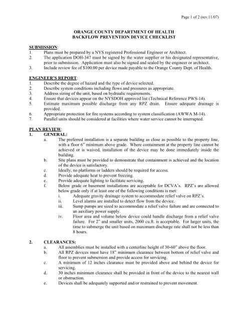
Page 1 of 2 (rev.11/07)<br />
ORANGE COUNTY DEPARTMENT OF HEALTH<br />
<strong>BACKFLOW</strong> <strong>PREVENTION</strong> <strong>DEVICE</strong> <strong>CHECKLIST</strong><br />
SUBMISSION:<br />
1. Plans must be prepared by a <strong>NY</strong>S registered Professional Engineer or Architect.<br />
2. The application DOH-347 must be signed by the water supplier or his designated representative,<br />
prior to submission. Application must also be signed and sealed by the engineer or architect.<br />
3. Include review fee of $100.00 per device made payable to the <strong>Orange</strong> <strong>County</strong> Dept. of Health.<br />
ENGINEER’S REPORT:<br />
1. Describe the degree of hazard and the type of device selected.<br />
2. Describe system conditions including flows and pressures as appropriate.<br />
3. Address sizing of the unit, based on hydraulic requirements.<br />
4. Ensure that devices appear on the <strong>NY</strong>SDOH approved list (Technical Reference PWS-14).<br />
5. Estimate maximum possible discharge from any RPZ drain. Ensure adequate drainage is<br />
provided.<br />
6. Appropriate protection for fire systems according to system classification (AWWA M-14).<br />
7. Parallel units should be considered at facilities where water service cannot be interrupted.<br />
PLAN REVIEW:<br />
1. GENERAL:<br />
a. The preferred installation is a separate building as close as possible to the property line,<br />
with a floor 6” minimum above grade. Where containment at the property line cannot be<br />
achieved or is waived, installation of the device may be done immediately inside the<br />
building.<br />
b. Site plans must be provided to demonstrate that containment is achieved and the location<br />
of the device is satisfactory.<br />
c. Ideally, no platforms or ladders should be required for access.<br />
d. Provide adequate heat to prevent freezing.<br />
e. Provide adequate lighting to facilitate servicing.<br />
f. Below grade or basement installations are acceptable for DCVA’s. RPZ’s are allowed<br />
below grade only if at least one of the following conditions is met:<br />
i. Adequate gravity drainage system to accommodate relief valve on RPZ’s.<br />
ii. Level alarms are installed to detect flow from the device.<br />
iii. Sump pumps are sized to accommodate a relief valve failure and are connected to<br />
an auxiliary power supply.<br />
iv. Floor area and volume below device could handle discharge from a relief valve<br />
failure. For 2” and smaller units, 2000 cu.ft. is acceptable. For larger units, the<br />
time to submerge the unit based on maximum discharge rate shall not be less than<br />
8 hours.<br />
2. CLEARANCES:<br />
a. All assemblies must be installed with a centerline height of 30-60” above the floor.<br />
b. All RPZ devices must have 18” minimum clearance between bottom of relief valve and<br />
floor to prevent submersion and provide access for servicing.<br />
c. A minimum of 12 inches clearance must be provided above and behind the device for<br />
servicing.<br />
d. 30 inches minimum clearance shall be provided in front of the device to the nearest wall<br />
or obstruction.<br />
e. Devices shall be adequately supported and/or restrained to prevent movement.
Page 2 of 2 (rev.11/07)<br />
3. DRAINAGE:<br />
a. Drainage shall be provided to accommodate discharge during testing or relief valve<br />
discharge.<br />
b. For RPZ devices, drainage must be sized to accommodate intermittent discharge and<br />
catastrophic failure of the relief valve.<br />
c. Discharge from relief valves must be readily visible. Adequate lighting must be<br />
provided.<br />
d. All drainage from RPZ’s must be by gravity drains through a properly designed air gap.<br />
Sump pumps are not allowed unless they are sized to accommodate maximum discharge<br />
and they are connected to emergency power sources. Manufacturer’s air gap fittings may<br />
not be sized to accommodate catastrophic discharge. Confirm capacity.<br />
e. Discharge piping from any relief valve must terminate at least 1 inch above grade or<br />
receiving receptacle.<br />
f. In pit installations, floors pitched to drain, and discharge piping must terminate above<br />
grade in an area not subject to flooding. The end of the pipe must be equipped with a<br />
rodent screen.<br />
4. INSTALLATION NOTES:<br />
a. Strainers are recommended prior to each backflow device on non-fire fighting lines<br />
ONLY! No strainer is to be used on a fire line without Insurance Underwriter approval.<br />
b. Assemblies should be specified and installed with manufacturer supplied valves.<br />
c. Water lines should be thoroughly flushed before installation of device to prevent debris<br />
fouling the device check valves.<br />
d. Devices must be mounted horizontally unless approved for vertical installation.<br />
e. Assemblies should not be installed in areas containing corrosive or toxic gases which<br />
could render the device inoperable.<br />
f. Due to inherent design of RPZ assemblies, fluctuating supply pressure on a low flow<br />
condition may cause nuisance dripping. Installation of a soft seated check valve ahead of<br />
the RPZ will often hold pressure constant during periods of low flow.<br />
g. Where the distance between the water meter and device is greater than 10 feet, all<br />
exposed piping should be marked “Feed line to Backflow Preventer – Do Not Tap” at 5<br />
foot intervals.