I R 1 2 3 4 5 6 7 8 9 10 11 12 13 T 14 15 16 - SDP/SI
I R 1 2 3 4 5 6 7 8 9 10 11 12 13 T 14 15 16 - SDP/SI
I R 1 2 3 4 5 6 7 8 9 10 11 12 13 T 14 15 16 - SDP/SI

Create successful ePaper yourself
Turn your PDF publications into a flip-book with our unique Google optimized e-Paper software.
I<br />
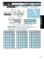
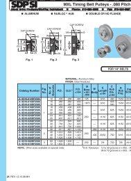
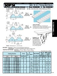
SPRING MOUNTS • ELLIPTIC LEAF TYPE<br />
R<br />
T<br />
1<br />
2<br />
NATO APPROVED NAVAL "X" MOUNTS<br />
MATERIAL:<br />
Leaves - 304 Stainless Steel<br />
Washers - Nylon and Stainless Steel<br />
Damping Compound - Polymer<br />
OPERATING TEMPERATURE:<br />
+50°F to +86°F (+<strong>10</strong>°C to +30°C)<br />
VIBRATION MODES:<br />
VERTICAL:<br />
PHONE: 5<strong>16</strong>.328.3300 • FAX: 5<strong>16</strong>.326.8827 • WWW.<strong>SDP</strong>-<strong>SI</strong>.COM<br />
Inch<br />
0 1<br />
3<br />
HORIZONTAL 1:<br />
HORIZONTAL 2:<br />
ØD<br />
L<br />
HEIGHT UNDER<br />
NOMINAL LOAD<br />
4<br />
h<br />
H<br />
5<br />
W<br />
Ød<br />
UNLOADED HEIGHT<br />
6<br />
MOUNTING<br />
HARDWARE<br />
DETAIL<br />
7<br />
8<br />
NATO APPROVED NAVAL “XM” MOUNTS<br />
FOR EXTREME ENVIRONMENTAL CONDITIONS<br />
9<br />
<strong>10</strong><br />
MATERIAL:<br />
Leaves - 304 Stainless Steel<br />
Washers - Nylon and Stainless Steel<br />
Damping Compound - Stainless Steel Mesh<br />
OPERATING TEMPERATURE:<br />
+238°F to +752°F (-<strong>15</strong>0°C to +400°C)<br />
<strong>11</strong><br />
<strong>12</strong><br />
ØD<br />
SPRING<br />
ASSY.<br />
<strong>13</strong><br />
H<br />
h<br />
BUSHING<br />
<strong>14</strong><br />
<strong>15</strong><br />
W<br />
Ød<br />
L<br />
WASHER<br />
<strong>16</strong><br />
8-62
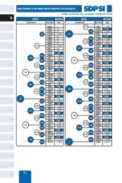
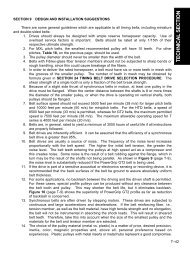
SPRING MOUNTS • ELLIPTIC LEAF TYPE<br />
NATO APPROVED NAVAL "X" and "XM" MOUNTS<br />
NATO Stock Numbers listed for "X" Mounts<br />
NATO Stock Numbers not available for "XM" Mounts<br />
Dimensions in ( ) are mm.<br />
INCH COMPONENT<br />
Catalog Number<br />
X Mounts<br />
A<strong>10</strong>Y<strong>15</strong>-57170025<br />
A<strong>10</strong>Y<strong>15</strong>-57180050<br />
A<strong>10</strong>Y<strong>15</strong>-57190<strong>10</strong>0<br />
A<strong>10</strong>Y<strong>15</strong>-57200<strong>15</strong>0<br />
A<strong>10</strong>Y<strong>15</strong>-572<strong>10</strong>250<br />
A<strong>10</strong>Y<strong>15</strong>-84290400<br />
A<strong>10</strong>Y<strong>15</strong>-84280700<br />
A<strong>10</strong>Y<strong>15</strong>-8427<strong>10</strong>00<br />
Catalog Number<br />
(Ref.)<br />
A<strong>10</strong>Y<strong>15</strong>-5717...<br />
A<strong>10</strong>Y<strong>15</strong>-5718...<br />
A<strong>10</strong>Y<strong>15</strong>-5719...<br />
A<strong>10</strong>Y<strong>15</strong>-5720...<br />
A<strong>10</strong>Y<strong>15</strong>-5721...<br />
A<strong>10</strong>Y<strong>15</strong>-8429...<br />
A<strong>10</strong>Y<strong>15</strong>-8428...<br />
A<strong>10</strong>Y<strong>15</strong>-8427...<br />
NATO Stock Number<br />
X Mounts<br />
(Ref.)<br />
5340-99-923-5717<br />
5340-99-923-5718<br />
5340-99-923-5719<br />
5340-99-923-5720<br />
5340-99-923-5721<br />
5340-99-520-8429<br />
5340-99-520-8428<br />
5340-99-520-8427<br />
L<br />
Length<br />
in. (mm)<br />
8 (203)<br />
8 (203)<br />
8.5 (2<strong>16</strong>)<br />
8.5 (2<strong>16</strong>)<br />
<strong>11</strong>.7 (297)<br />
<strong>11</strong>.7 (297)<br />
<strong>11</strong>.7 (297)<br />
<strong>11</strong>.7 (297)<br />
Weight<br />
lb. (kg)<br />
1.5 (0.68)<br />
1.75 (0.8)<br />
2.25 (1.02)<br />
2.5 (1.<strong>13</strong>)<br />
2.75 (1.25)<br />
<strong>13</strong> (5.9)<br />
<strong>14</strong>.5 (6.58)<br />
<strong>16</strong> (7.26)<br />
W<br />
Width<br />
in. (mm)<br />
2 (51)<br />
2 (51)<br />
2 (51)<br />
2 (51)<br />
4 (<strong>10</strong>2)<br />
4 (<strong>10</strong>2)<br />
4 (<strong>10</strong>2)<br />
4 (<strong>10</strong>2)<br />
Vertical<br />
lbf / in.<br />
(kgf / cm)<br />
75 (<strong>13</strong>.39)<br />
<strong>15</strong>0 (26.79)<br />
250 (44.65)<br />
400 (71.43)<br />
650 (<strong>11</strong>6.08)<br />
2300 (4<strong>10</strong>.74)<br />
3000 (535.75)<br />
4800 (857.2)<br />
PHONE: 5<strong>16</strong>.328.3300 • FAX: 5<strong>16</strong>.326.8827 • WWW.<strong>SDP</strong>-<strong>SI</strong>.COM<br />
INCH COMPONENT<br />
Catalog Number<br />
XM Mounts<br />
A<strong>10</strong>Y<strong>15</strong>-5717M0025<br />
A<strong>10</strong>Y<strong>15</strong>-5718M0050<br />
A<strong>10</strong>Y<strong>15</strong>-5719M0<strong>10</strong>0<br />
A<strong>10</strong>Y<strong>15</strong>-5720M0<strong>15</strong>0<br />
A<strong>10</strong>Y<strong>15</strong>-5721M0250<br />
A<strong>10</strong>Y<strong>15</strong>-8429M0400<br />
A<strong>10</strong>Y<strong>15</strong>-8428M0700<br />
A<strong>10</strong>Y<strong>15</strong>-8427M<strong>10</strong>00<br />
H Height<br />
Unloaded With<br />
Washers<br />
in. (mm)<br />
4.5 (<strong>11</strong>4)<br />
4.5 (<strong>11</strong>4)<br />
5.25 (<strong>13</strong>3)<br />
5.25 (<strong>13</strong>3)<br />
7.5 (190)<br />
7.5 (190)<br />
7.5 (190)<br />
7.5 (190)<br />
Static Stiffness<br />
Horizontal 1<br />
lbf / in.<br />
(kgf / cm)<br />
40 (7.<strong>14</strong>)<br />
80 (<strong>14</strong>.29)<br />
<strong>13</strong>5 (24.<strong>11</strong>)<br />
220 (39.29)<br />
350 (62.5)<br />
620 (1<strong>10</strong>.72)<br />
760 (<strong>13</strong>5.72)<br />
1<strong>10</strong>0 (196.44)<br />
h Height<br />
Loaded with<br />
Washers<br />
in. (mm)<br />
4.21 (<strong>10</strong>7)<br />
4.17 (<strong>10</strong>6)<br />
4.88 (<strong>12</strong>4)<br />
4.88 (<strong>12</strong>4)<br />
4.8 (<strong>12</strong>2)<br />
7.28 (185)<br />
7.32 (186)<br />
7.24 (184)<br />
Horizontal 2<br />
lbf / in.<br />
(kgf / cm)<br />
<strong>10</strong>0 (17.88)<br />
200 (35.72)<br />
330 (58.93)<br />
520 (92.86)<br />
850 (<strong>15</strong>1.8)<br />
3070 (548.25)<br />
2700 (482.17)<br />
4000 (7<strong>14</strong>.33)<br />
Nominal<br />
Load<br />
lbf (kgf)<br />
22 (<strong>10</strong>)<br />
44 (20)<br />
99 (45)<br />
<strong>15</strong>4 (70)<br />
242 (1<strong>10</strong>)<br />
397 (180)<br />
705 (320)<br />
992 (450)<br />
D Dia.<br />
Washers<br />
in. (mm)<br />
1.25 (31.75)<br />
1.25 (31.75)<br />
1.25 (31.75)<br />
1.25 (31.75)<br />
1.25 (31.75)<br />
2.5 (63.5)<br />
2.5 (63.5)<br />
2.5 (63.5)<br />
Vertical<br />
Hz<br />
7.5<br />
7.5<br />
7.5<br />
7.5<br />
7.5<br />
<strong>10</strong>.5<br />
7.5<br />
7.5<br />
lbf<br />
Inch<br />
0 1<br />
Load Range<br />
20 – 40<br />
40 – 77<br />
77 – <strong>12</strong>1<br />
<strong>12</strong>1 – 198<br />
198 – 298<br />
298 – 551<br />
551 – 838<br />
838 – <strong>12</strong><strong>12</strong><br />
d Dia.<br />
Bolt Hole<br />
in. (mm)<br />
.354 (9)<br />
.354 (9)<br />
.5<strong>12</strong> (<strong>13</strong>)<br />
.5<strong>12</strong> (<strong>13</strong>)<br />
.5<strong>12</strong> (<strong>13</strong>)<br />
.827 (21)<br />
.827 (21)<br />
.827 (21)<br />
Natural Frequencies<br />
Horizontal 1<br />
Hz<br />
4.5<br />
4.5<br />
4.5<br />
4.5<br />
4.5<br />
4.5<br />
4.0<br />
4.0<br />
kgf<br />
9 – 18<br />
18 – 35<br />
35 – 55<br />
55 – 90<br />
90 – <strong>13</strong>5<br />
<strong>13</strong>5 – 250<br />
250 – 380<br />
380 – 550<br />
Bolt Size<br />
UNF in.<br />
(nearest<br />
metric)<br />
5/<strong>16</strong> (8)<br />
5/<strong>16</strong> (8)<br />
1/2 (<strong>12</strong>)<br />
1/2 (<strong>12</strong>)<br />
1/2 (<strong>12</strong>)<br />
3/4 (20)<br />
3/4 (20)<br />
3/4 (20)<br />
Horizontal 2<br />
Hz<br />
5.5<br />
5.5<br />
5.5<br />
5.5<br />
5.5<br />
5.5<br />
5.0<br />
5.0<br />
I<br />
R<br />
T<br />
1<br />
2<br />
3<br />
4<br />
5<br />
6<br />
7<br />
8<br />
9<br />
<strong>10</strong><br />
<strong>11</strong><br />
<strong>12</strong><br />
<strong>13</strong><br />
<strong>14</strong><br />
<strong>15</strong><br />
8-63<br />
<strong>16</strong>
I<br />
R<br />
T<br />
1<br />
2<br />
3<br />
4<br />
5<br />
6<br />
7<br />
8<br />
9<br />
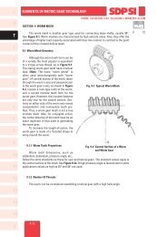
ELLIPTIC LEAF SPRING MOUNTING (NAVAL “X” TYPE)<br />
PHONE: 5<strong>16</strong>.328.3300 • FAX: 5<strong>16</strong>.326.8827 • WWW.<strong>SDP</strong>-<strong>SI</strong>.COM<br />
This type of vibration and shock isolator was designed specifically for shipboard or mobile<br />
applications. They are particularly suitable to protect delicate shipboard equipment from shock due<br />
to underwater explosions or sudden stoppage of vehicles for vehicle mounted equipment.<br />
All materials used are impervious to corrosion and will operate efficiently under a wide range<br />
of temperature, making the units well-suited for naval or aircraft applications. Their basic design<br />
employs two or more high-tensile stainless steel "U" formed leaves, situated at each end, forming<br />
an elliptical shape when joined together in the center portion with face plates. The spaces between<br />
the "U" formed leaves are filled with a specially developed polymer or stainless steel mesh.<br />
Inch<br />
0 1<br />
Nonmetallic collars backed by stainless steel washers are supplied for load attachment, while providing noise reduction.<br />
Inch size or metric size bolts may be used for fastening of the equipment to the base or foundation.<br />
Low transmitted shock accelerations are obtained by combining large permitted static deflection in every direction<br />
with a high energy loss within the mount. The high damping efficiency is obtained by the polymer which has a very low<br />
static stiffness. The load bearing characteristics are determined by the metal construction of the mountings. These mounts<br />
may be used in tension as well as compression.<br />
The "X" Mount is one of those rare breeds which gives both vibration isolation and shock protection. Its low frequency<br />
ensures effective vibration isolation, except where the resonant frequency of the surrounding structure may be sympathetic<br />
with the mount's natural frequency. Similarly, care must be taken during transportation of equipment supported by "X"<br />
Mounts.<br />
The main disadvantage of the mount is that transmissibility at resonance is high. In most applications this is not critical<br />
as the "X" Mounts are placed in areas that do not coincide with its resonant frequency. This special applications mount<br />
may be of particular interest not only for its improved vibration performance at low temperature, but also its lower natural<br />
frequency at room temperatures. This may avoid the need of trying to reduce the natural frequency by means of adding<br />
a rubber washer in tandem, as this procedure also increases the transmissibility at resonance of the system.<br />
Shock protection of the new design has the added benefit of durability under repeated shocks at low temperatures.<br />
INSTALLATION OF "X" MOUNTS<br />
Due to the sophisticated nature of the "X" Mounts, it is essential that they be correctly loaded. Incorrect loading will<br />
mean inadequate shock protection (this is true even in underloaded situations).<br />
Bad Practice<br />
Due to the shape and size of the "X" Mount, there is a strong tendency to use the space created as storage. Needless<br />
to say, any such placement can render the shock protection useless.<br />
Preferred Systems<br />
Mounts supporting the system underneath only, with the center of gravity in the lower third of the unit, is preferred.<br />
When this is impossible, a fully suspended method should be used. Top steadies can be used where it is difficult to choose<br />
mounts to support the weight using a fully suspended configuration.<br />
The practice of combining units on one raft is often carried out to ensure that a suitable loading is obtained. This<br />
practice is especially important for operator-controlled equipment; the seat can be mounted on the raft as well.<br />
Orientation<br />
Where possible, the horizontal roll axis should be fore and aft, to minimize equipment movement due to ship roll, but<br />
any orientation is acceptable for shock protection. It is advisable to place mounts on any one piece of equipment in the<br />
same direction.<br />
<strong>10</strong><br />
<strong>11</strong><br />
<strong>12</strong><br />
TYPICAL APPLICATIONS INCLUDE:<br />
Heavy Machine Tools<br />
Air Compressors<br />
Engine Suspension<br />
Machine Mounting<br />
Machine Craft Installations<br />
Laboratory Equipment<br />
Electric Motors<br />
Factory Test Gear<br />
Seat Suspension in Aircraft and Vehicles<br />
Radar Communications Equipment<br />
Electronic Control Equipment<br />
Equipment Mountings in Tanks and Other Military Vehicles<br />
Bomb and Other Lifting Gear<br />
Refrigeration Compressors<br />
Mobile Vehicles<br />
Fuel Tanks<br />
Blowers and Fans<br />
Pumps<br />
<strong>13</strong><br />
<strong>14</strong><br />
<strong>15</strong><br />
<strong>16</strong><br />
8-64
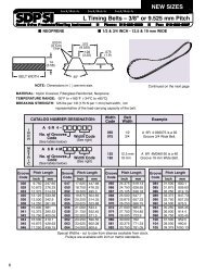
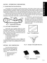
SPRING MOUNT • ELLIPTIC LEAF TYPE<br />
NATO APPROVED NAVAL “X” MOUNTS<br />
LIGHTWEIGHT<br />
MATERIAL:<br />
Leaves - 304 Stainless Steel<br />
Washers - Nylon and Stainless Steel<br />
Damping Compound - Polymer<br />
OPERATING TEMPERATURE:<br />
+50°F to +86°F (+<strong>10</strong>°C to +30°C)<br />
PHONE: 5<strong>16</strong>.328.3300 • FAX: 5<strong>16</strong>.326.8827 • WWW.<strong>SDP</strong>-<strong>SI</strong>.COM<br />
Inch<br />
0 1<br />
I<br />
R<br />
T<br />
1<br />
FEATURES:<br />
The <strong>13</strong>.2 lbf (6 kgf) Mount is designed to isolate lightweight<br />
equipment (i.e. computers, printers, electronics panels, etc.)<br />
from shock and vibration and has similar properties to the<br />
present range of ‘X’ mounts with some reduction in the<br />
available deflection under shock conditions.<br />
2<br />
3<br />
VIBRATION MODES:<br />
VERTICAL:<br />
M8 BOLT<br />
HEIGHT UNDER<br />
NOMINAL LOAD<br />
4<br />
HORIZONTAL 1:<br />
HORIZONTAL 2:<br />
2.87<br />
(73)<br />
3.23<br />
(82)<br />
5<br />
6<br />
INCH COMPONENT<br />
Catalog Number<br />
*A<strong>10</strong>Y<strong>15</strong>-392<strong>10</strong>0<strong>13</strong><br />
.98<br />
(25)<br />
Nominal<br />
Load<br />
lbf (kgf)<br />
Ø.33 (8.5)<br />
5.27<br />
(<strong>13</strong>4)<br />
Ø.79 (20)<br />
NOTE: Dimensions in ( ) are mm.<br />
Load<br />
Range<br />
lbf (kgf)<br />
Bolt Size UNF<br />
in.<br />
(nearest metric)<br />
UNLOADED<br />
HEIGHT<br />
Weight<br />
Excluding Bolt<br />
lb. (kg)<br />
<strong>13</strong>.2 (6) 8.8 – <strong>13</strong>.2 (4 – 6) 5/<strong>16</strong> (8) .29 (0.<strong>13</strong>)<br />
Static Stiffness<br />
Natural Frequencies<br />
Catalog Number Vertical Horizontal 1 Horizontal 2<br />
(Ref.)<br />
lbf / in. lbf / in. lbf / in.<br />
Vertical Horizontal 1 Horizontal 2<br />
(kgf / cm) (kgf / cm) (kgf / cm)<br />
Hz<br />
Hz<br />
Hz<br />
A<strong>10</strong>Y<strong>15</strong>-392<strong>10</strong>0<strong>13</strong> 33 (5.91) 43 (7.68) 18 (3.25) 7.2 – 8.9 8.3 – <strong>10</strong>.1 5.4 – 6.6<br />
* NATO Stock Number: 5340-99-665-3921<br />
7<br />
8<br />
9<br />
<strong>10</strong><br />
<strong>11</strong><br />
<strong>12</strong><br />
<strong>13</strong><br />
<strong>14</strong><br />
<strong>15</strong><br />
8-65<br />
<strong>16</strong>
I<br />
R<br />
T<br />
1<br />
2<br />
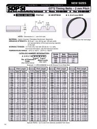
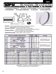
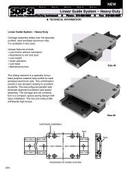
ELLIPTIC LEAF SPRING MOUNT TEST DATA<br />
TRANSMIS<strong>SI</strong>BILITY / TEMPERATURE / RESONANCE:<br />
a<br />
b<br />
c<br />
d<br />
e<br />
f<br />
Temp °C f n (Hz) Q<br />
41.6 6.2 <strong>10</strong>.2<br />
29.9 6.6 6.1<br />
19.7 7.6 2.8<br />
<strong>10</strong>.2 <strong>13</strong>.0 2.2<br />
0.5 22.0 4.0<br />
–<strong>16</strong>.1 29.6 22.7<br />
30<br />
PHONE: 5<strong>16</strong>.328.3300 • FAX: 5<strong>16</strong>.326.8827 • WWW.<strong>SDP</strong>-<strong>SI</strong>.COM<br />
Inch<br />
0 1<br />
3<br />
<strong>10</strong>.0<br />
3.0<br />
20<br />
<strong>10</strong><br />
4<br />
Q<br />
1.0<br />
0.3<br />
0<br />
dB<br />
-<strong>10</strong><br />
5<br />
6<br />
0.1<br />
-20<br />
-30<br />
-40<br />
5<br />
f<br />
e<br />
d<br />
c<br />
b<br />
a<br />
6 7 <strong>10</strong> 20 30 50 <strong>10</strong>0<br />
7<br />
Impressed frequency (Hz)<br />
8<br />
"Q" / TEMPERATURE<br />
20<br />
9<br />
"Q" =<br />
Real Stiffness<br />
Complex Stiffness<br />
<strong>10</strong><br />
"Q" / Factor<br />
<strong>10</strong><br />
<strong>11</strong><br />
<strong>12</strong><br />
<strong>13</strong><br />
<strong>14</strong><br />
<strong>15</strong><br />
<strong>16</strong><br />
-40 -30 -20 -<strong>10</strong> 0 <strong>10</strong> 20<br />
8-66<br />
TEMPERATURE °C<br />
NATURAL FREQUENCY / TEMPERATURE<br />
30<br />
20<br />
<strong>10</strong><br />
30 40<br />
Natural Frequency<br />
-40 -30 -20 -<strong>10</strong> 0 <strong>10</strong> 20 30 40<br />
TEMPERATURE °C