FRS® Fusion and Reconstruction System Standard Staple ... - Biomet
FRS® Fusion and Reconstruction System Standard Staple ... - Biomet
FRS® Fusion and Reconstruction System Standard Staple ... - Biomet

Create successful ePaper yourself
Turn your PDF publications into a flip-book with our unique Google optimized e-Paper software.
St<strong>and</strong>ard <strong>Staple</strong><br />
Basic Product <strong>and</strong> Instrument<br />
Utilization Technique<br />
®<br />
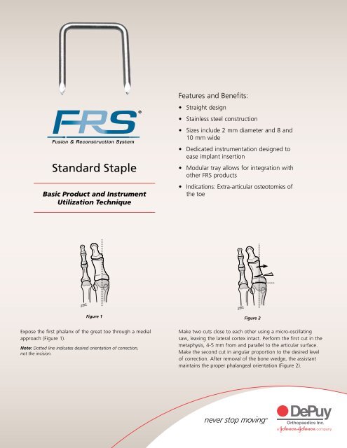
Features <strong>and</strong> Benefits:<br />
• Straight design<br />
• Stainless steel construction<br />
• Sizes include 2 mm diameter <strong>and</strong> 8 <strong>and</strong><br />
10 mm wide<br />
• Dedicated instrumentation designed to<br />
ease implant insertion<br />
• Modular tray allows for integration with<br />
other FRS products<br />
• Indications: Extra-articular osteotomies of<br />
the toe<br />
Figure 1 Figure 2<br />
Expose the first phalanx of the great toe through a medial<br />
approach (Figure 1).<br />
Note: Dotted line indicates desired orientation of correction,<br />
not the incision.<br />
Make two cuts close to each other using a micro-oscillating<br />
saw, leaving the lateral cortex intact. Perform the first cut in the<br />
metaphysis, 4-5 mm from <strong>and</strong> parallel to the articular surface.<br />
Make the second cut in angular proportion to the desired level<br />
of correction. After removal of the bone wedge, the assistant<br />
maintains the proper phalangeal orientation (Figure 2).
Figure 3<br />
Figure 4a<br />
Figure 4b<br />
Drill a single pilot hole cortex to cortex into the distal fragment<br />
with the 1.0 mm diameter smooth pin (Cat. No. PA010)<br />
(Figure 3). Depending on the distance to the metatarsal<br />
phalangeal joint <strong>and</strong> site surface angle, the appropriate staple<br />
(8 or 10 mm wide)) should be selected.<br />
Note: The 1.0 mm diameter pin is marked with a black b<strong>and</strong> around the<br />
circumference of the proximal (rounded) end.<br />
Utilize the staple holder (Straight, Cat. No. 8270-01-000) to hold<br />
<strong>and</strong> insert the staple with its two legs parallel to the joint line<br />
(Figures 4a <strong>and</strong> 4b). Final staple placement can be accomplished<br />
with the appropriate staple impactor (Straight, Cat. No.<br />
8270-03-000).<br />
Note: Special attention should be taken not to violate the joint space.<br />
Essential Product Information<br />
Important This essential product information does not include all of the information necessary for<br />
selection <strong>and</strong> use of a device. Please see full labeling for all necessary information.<br />
Indications The st<strong>and</strong>ard orthopaedic staple is intended to provide the orthopaedic surgeon a<br />
means of bone fixation <strong>and</strong> help in the general management of fractures <strong>and</strong> reconstructive surgeries.<br />
These implants are intended as a guide to normal healing <strong>and</strong> are not intended to replace normal body<br />
structure or bear the weight of the body in the presence of incomplete bone healing.<br />
Contraindications This device is contraindicated: in the presence of active infection; in cases<br />
with malignant primary or metastatic tumors which preclude adequate bone support or fixation unless<br />
supplemental means of fixation are used; in conditions that tend to retard healing such as blood<br />
supply limitations, previous infections etc.; if insufficient quantity or quality of bone does not permit<br />
stabilization of the fracture complex; in conditions that restrict the patient’s ability or willingness to<br />
follow postoperative instructions; <strong>and</strong> in cases where material sensitivity is suspected.<br />
Warnings <strong>and</strong> Precautions This device is intended for partial weight-bearing or non-weightbearing<br />
applications <strong>and</strong> cannot be expected to withst<strong>and</strong> the unsupported stresses of full weight<br />
bearing. This device is not approved for attachment or fixation to the posterior elements (pedicles) of<br />
the cervical, thoracic or lumbar spine.<br />
Adverse Events The following are the most frequent adverse events after fixation with orthopaedic<br />
screws: loosening, bending, cracking or fracture of the components or loss of fixation in bone<br />
attributable to nonunion, osteoporosis, markedly unstable comminuted fractures; loss of anatomic<br />
position with nonunion or malunion with rotation or angulation; infection <strong>and</strong> adverse reactions to the<br />
device material.<br />
Implants<br />
Cat. No. Description<br />
P106<br />
St<strong>and</strong>ard <strong>Staple</strong>, Straight 10 mm<br />
P107<br />
St<strong>and</strong>ard <strong>Staple</strong>, Straight 8 mm<br />
Instruments<br />
Cat. No. Description<br />
8270-00-000 St<strong>and</strong>ard <strong>Staple</strong> Tray<br />
8270-01-000 St<strong>and</strong>ard <strong>Staple</strong> Holder, Straight<br />
8270-03-000 St<strong>and</strong>ard <strong>Staple</strong> Impactor, Straight<br />
PA010 Smooth Pin 1.0 mm<br />
DePuy Orthopaedics, Inc.<br />
700 Orthopaedic Drive<br />
Warsaw, IN 46581-0988<br />
USA<br />
Tel: +1 (800) 366 8143<br />
Fax: +1 (574) 371 4865<br />
www.depuy.com<br />
©DePuy Orthopaedics, Inc. 2011.<br />
All rights reserved.<br />
0612-53-050 (Rev. 4) 1.5M 0411