Fractional Dual-Modulus Prescaler with Regenerative Divider
Fractional Dual-Modulus Prescaler with Regenerative Divider
Fractional Dual-Modulus Prescaler with Regenerative Divider

Create successful ePaper yourself
Turn your PDF publications into a flip-book with our unique Google optimized e-Paper software.
The 13th IEEE International Symposium on Consumer Electronics (ISCE2009)<br />
<strong>Fractional</strong> <strong>Dual</strong>-<strong>Modulus</strong> <strong>Prescaler</strong> <strong>with</strong><br />
<strong>Regenerative</strong> <strong>Divider</strong><br />
Yue-Fang Kuo and Ro-Min Weng<br />
Dept. of Electrical Engineering,<br />
National Dong Hwa University,<br />
Hualien 97401, Taiwan, Republic of China<br />
romin@mail.ndhu.edu.tw<br />
Abstract—A fractional dual-modulus prescaler (FDMP) <strong>with</strong><br />
regenerative divider for 5 GHz band is presented using 0.13 µm<br />
CMOS technology. It provides a solution to generate a dualmodulus<br />
fractional division ratio which keeps up <strong>with</strong> high<br />
operation frequency from a voltage-controlled oscillator. The<br />
maximum operation frequency of FDMP is 6.3 GHz consuming<br />
6.75 mW at 1.2 V supply voltage. The proposed FDMP achieves<br />
both high operation frequency and large output swing of the<br />
quadrature outputs.<br />
f REF<br />
Phase<br />
Frequency<br />
Detector<br />
Q<br />
R<br />
S<br />
Charge<br />
Pump<br />
Pulse (N P )<br />
Counter<br />
Sallower (N S )<br />
Counter<br />
Loop Filter<br />
<strong>Dual</strong>-<strong>Modulus</strong><br />
<strong>Prescaler</strong><br />
N A /N A +1<br />
<strong>Modulus</strong><br />
Control<br />
VCO<br />
f VCO,I<br />
f VCO,Q<br />
f VCO<br />
Keywords-<strong>Fractional</strong> <strong>Dual</strong>-<strong>Modulus</strong> <strong>Prescaler</strong>; <strong>Regenerative</strong><br />
<strong>Divider</strong>; Miller <strong>Divider</strong>.<br />
I. INTRODUCTION<br />
A dual-modulus prescaler (DMP) is a key block of a<br />
frequency divider in a frequency synthesizer. The division<br />
number of a pulse-swallower divider is decided by DMP. To<br />
keep up <strong>with</strong> high frequency output from a voltage-controlled<br />
oscillator (VCO) and to reduce the power consumption, there is<br />
a trade-off between the speed and the divide-by-N of DMP.<br />
Commonly, a fixed-ratio prescaler is inserted between DMP<br />
and VCO in order to relax the speed constraint of DMP [1].<br />
However, the channel spacing becomes large and resolution is<br />
decreased by this solution. For maintaining the same channel<br />
spacing, the reference frequency f REF is required to be reduced<br />
by a factor of the fixed-ratio. Low reference frequency results<br />
in decreasing the useful bandwidth of a phase-locked loop<br />
(PLL). This solution increases the settling time and decreases<br />
phase noise performance. In this work, a new dual-modulus<br />
prescaler based on regenerative divider is introduced to solve<br />
the above problems and to achieve high operating frequency<br />
<strong>with</strong> the fractional division ratio.<br />
II.<br />
CIRCUIT DESIGN<br />
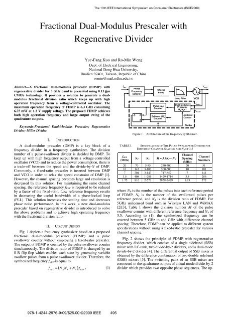
Fig. 1 depicts a frequency synthesizer based on a proposed<br />
fractional dual-modulus prescaler (FDMP) and a pulse<br />
swallower counter <strong>with</strong>out employing a fixed-ratio prescaler.<br />
The output of FDMP is counted by the pulse swallower counter<br />
simultaneously. The division ratio of FDMP is changed by an<br />
S-R flip-flop which enables each state by generating variable<br />
swallow pulses from a pulse swallower divider. Therefore, the<br />
synthesized frequency f VCO is equal to<br />
VCO<br />
( N A<br />
N P<br />
N S<br />
) f REF<br />
f = + , (1)<br />
TABLE I.<br />
f REF<br />
(MHz)<br />
<strong>Divider</strong><br />
Figure 1. Architecture of the frequency synthesizer.<br />
SPECIFICATION OF THE PULSE SWALLOWER DIVIDER FOR<br />
DIFFERENT CHANNEL SPACING AND N A OF 3.5<br />
N P N S M = 3.5N P + N S<br />
Channel<br />
Spacing<br />
(MHz)<br />
Channel<br />
Numbers<br />
20 70 5-55 250-300 20 51<br />
10 142 3-103 500-600 10 101<br />
7 204 3-143 717-857 7 141<br />
3.5 408 1-286 1429-1714 3.5 286<br />
1.75 816 2-573 2858-3429 1.75 572<br />
where N P is the number of the pulses into each reference period<br />
of FDMP, N S is the number of the swallowed pulses per<br />
reference period, and N A is the division ratio of FDMP. For<br />
5GHz unlicensed band such as Wireless LAN and WiMAX<br />
[2][3], Table I shows the division number M of the pulse<br />
swallower counter <strong>with</strong> different reference frequency and N A of<br />
3.5. According to (1), the synthesized frequency can be<br />
covered between 5 GHz to and GHz <strong>with</strong> difference channel<br />
spacing. Therefore, FDMP can be applied to different system<br />
specifications <strong>with</strong>out using a fixed-ratio prescaler for various<br />
channel spacing.<br />
Fig. 2 shows the principle of FDMP <strong>with</strong> regenerative<br />
frequency divider, which consists of a single sideband (SSB)<br />
mixer <strong>with</strong> LC-tank, two divide-by-2 dividers, and a dual-mode<br />
divide-by-2 divider [4]. The differential output of SSB mixer is<br />
obtained by the difference combination of two double sideband<br />
(DSB) mixers [5]. The switching pairs of an SSB mixer are<br />
connected to the quadrature outputs of a dual-mode divide-by-2<br />
divider which provides two opposite phase sequences. The up-<br />
978-1-4244-2976-9/09/$25.00 ©2009 IEEE 495
SSB Mixer<br />
DOWN<br />
Conversion<br />
UP<br />
Conversion<br />
Voltage<br />
Controlled<br />
Oscillator<br />
f VCO,I<br />
f VCO,Q<br />
DSB<br />
Mixer1<br />
+<br />
+<br />
2 N f VCO<br />
2 N +1<br />
C<br />
2<br />
2L<br />
2 N f VCO<br />
2 N -1<br />
+<br />
f out1<br />
-<br />
f out4,I<br />
2 N f VCO<br />
LC-Tank<br />
2 N + 1<br />
f out4,Q<br />
<strong>Divider</strong><br />
1/2<br />
+<br />
f out2<br />
-<br />
2 N -1 f VCO<br />
2 N + 1<br />
N = 3<br />
<strong>Divider</strong><br />
1/2<br />
+<br />
f out3<br />
-<br />
2 N -2 f VCO<br />
2 N + 1<br />
<strong>Dual</strong>-Mode<br />
<strong>Divider</strong><br />
1/2<br />
DSB<br />
Mixer2<br />
2 N -3 f VCO<br />
2 N + 1<br />
Figure 2. Principle of FDMP.<br />
V DD<br />
LC-Tank<br />
L<br />
L<br />
Mode<br />
C<br />
C<br />
f out1<br />
+<br />
f VCO,I<br />
-<br />
DFF1<br />
D Q<br />
DFF2<br />
D Q<br />
M 1 M 2 M 3 M 4<br />
M 7 M 8 M 9 M 10<br />
f MCML<br />
out2<br />
f out3<br />
D Q D Q<br />
Divide-by-2<br />
CK CK CK CK<br />
M 5 R M 6 M 11 M 12<br />
1<br />
R +<br />
2<br />
f VCO,Q<br />
-<br />
MCML Divide-by-2<br />
I S I S<br />
I S<br />
I S<br />
Mode = 1<br />
CW<br />
DSB Mixer2<br />
DSB Mixer1<br />
M 34 M 35 M 36<br />
t<br />
f out4,I1<br />
f out4,Q2,270 f out4,Q1,90<br />
f out4,I2 f<br />
f out4,I1,0 out4,Q1<br />
f<br />
Mode = 0<br />
out4,Q2 CCW<br />
M 13 M 14 M 15 M 16 M 17 M 18 M 19 M 20 M 21 M 22 M 23 M 24<br />
t<br />
M 25 M 26 M 27<br />
M 28 M 29 M 30 f out4,Q1,270 f out4,Q2,90<br />
f out4,I1,0<br />
Mode<br />
M 31 M 32<br />
M 33<br />
V DD<br />
Mode<br />
I SS<br />
<strong>Dual</strong>-Mode Divide-by-2 <strong>Divider</strong><br />
conversion or down-conversion output of an SSB mixer can be<br />
obtained by choosing different quadrature phase to tune the<br />
LC-tank load. When center frequency of the resonant LC-tank<br />
is around (2 N f VCO )/(2 N -1), the SSB mixer generates the upconversion<br />
and suppresses the down-sideband. The<br />
regenerative modulation of the input sinusoidal signal is<br />
generated from f VCO to (2 N-3 f VCO )/(2 N -1). The output frequency<br />
of FDMP will be succeed to achieve the differential output<br />
frequency, f OUT = (1/3.5) f VCO , when N is equal to 3. Assuming<br />
that the resonant LC-tank tunes the center frequency from<br />
(2 N f VCO )/(2 N -1) to (2 N f VCO )/(2 N +1) at the output of the SSB<br />
mixer. In additional, the dual-mode divider changes the<br />
opposite quadrature phase at the frequency of (2 N-3 f VCO )/(2 N +1).<br />
Then, the up-sideband suppression can be increased where<br />
FDMP is divided by 4.5.<br />
A Gilbert double-balanced DSB mixer is used for<br />
providing the quadrature inputs of the SSB mixer which<br />
accomplish addition and subtraction of frequency, as shown in<br />
Fig. 3. The resonant LC-tank composes of a symmetric shared<br />
inductor <strong>with</strong> centre-tap and two switched capacitors. The<br />
linearity and flat voltage gain can be improved during the<br />
Figure 3. Schematic of proposed FDMP<br />
desired division ratio of FDMP. For high-frequency operation<br />
of the SSB mixer, its output is halved by a divide-by-2 divider<br />
<strong>with</strong> MOS current mode logic (MCML) circuits which<br />
achieves both low phase noise and wide operating frequency<br />
range of (2 N+1 f VCO )/(2 2N -1) [6]. The schematic of the dual-mode<br />
divide-by-2 divider is introduced by Lee [7]. Two phase<br />
patterns of both clockwise and counterclockwise sequences are<br />
provided. According to the pattern selection switch signal<br />
Mode, the tail current of transistor M 31 (M 32 ) steers the MCML<br />
circuits and controls different phases transferring to the output<br />
ports.<br />
III.<br />
SIMULATION RESULT<br />
The proposed regenerative frequency divider is simulated<br />
<strong>with</strong> 0.13 µm CMOS process parameters at 1.2 V power<br />
supply. Fig. 4 shows the output signal of the proposed divider<br />
<strong>with</strong> an input 200 mV peak-to-peak voltage of 6 GHz<br />
operating frequency. It is obvious that the input signal of a<br />
divide-by-4.5 state has one more delay than that of a divideby-3.5<br />
state. Fig. 5 shows the sensitivity curves of the<br />
proposed divider in two different division ratios. The results<br />
496
show that the proposed divider achieves large output swing<br />
<strong>with</strong> small input signal between 5 GHz and 6 GHz. The<br />
operating range of FDMP is limited by the center frequency of<br />
the resonant LC-tank. With 6 GHz input signal, the output<br />
spectrum of SSB mixer shows Fig. 6. In Fig. 6(a), the SSB<br />
mixer generates a down-conversion signal of 6.855 GHz and<br />
suppresses both 3.43 GHz and 10.28 GHz below 30dB. The<br />
sideband around 2.668 GHz and 8 GHz are at least 25dB lower<br />
than output of SSB mixer at 5.335 GHz, as shown in Fig. 6(b).<br />
The input signal of VCO and the sideband signal are<br />
effectively suppressed by the resonant LC-tank. The power<br />
consumption <strong>with</strong>in the operating frequency band is less than<br />
6.75 mW.<br />
IV.<br />
CONCLUSION<br />
A novel fractional dual-modulus precsaler <strong>with</strong><br />
regenerative divider is presented. The proposed presclaer<br />
provides a dual-modulus fractional division ratio for keeping<br />
up <strong>with</strong> high operation frequency under a small input voltage<br />
swing. The simulated results prove that the proposed prescaler<br />
achieves high operation frequency <strong>with</strong> a large output swing.<br />
The designed prescaler can be further applied to the frequency<br />
dividers for high speed systems.<br />
1.6<br />
1.4<br />
1.2<br />
Divide-by-3.5<br />
Divide-by-4.5<br />
fvco<br />
fout3<br />
Mode<br />
ACKNOWLEDGMENT<br />
The tsmc 0.13µm CMOS process parameters for this work<br />
are supported by the National Chip Implementation Center<br />
(CIC) of the National Applied Research Laboratories, Taiwan.<br />
REFERENCES<br />
[1] S. Pellerano, S. Levantino, C. Samori, and A. L. Lacaita, “A 13.5-mW<br />
5-GHz Frequency Synthesizer With Dynamic-Logic Frequency<br />
<strong>Divider</strong>,” IEEE J. Solid-State Circuits, vol. 39, no. 2, pp. 378-383, Feb.<br />
2004.<br />
[2] T. H. Lee, H. Samavati, and H. R. Rategh, “5-GHz CMOS Wireless<br />
LANs,” IEEE Trans.Microw. Theory Tech., vol. 50, no. 1, pp. 268-280,<br />
Jan. 2002.<br />
[3] G. C. T. Leung and H. C. Luong, “A 1-V 5.2-GHz CMOS Synthesizer<br />
for WLAN Applications,” IEEE J. Solid-State Circuits, vol. 39, no. 11,<br />
pp. 1873-1882, Nov. 2004.<br />
[4] K. Sengupta, T. K. Bhattacharcharyya, and H. Hashemi, “A Nonlinear<br />
Transient Analysis of <strong>Regenerative</strong> Frequency <strong>Divider</strong>s,” IEEE Trans.<br />
Circuits Syst. I, Reg. Papers, vol. 54, no. 12, pp. 2646-60, Dec. 2007.<br />
[5] Y. F. Kuo and R. M. Weng, “<strong>Regenerative</strong> Frequency <strong>Divider</strong> for 14<br />
Sub-band UWB Applications,” Electron. Lett., vo1. 44, no. 2, pp. 111-3,<br />
Jan. 2008.<br />
[6] X. P. Yu, M. A. Do, J. G. Ma, K. S. Yeo, R. Wu, and G. Q. Yan, “1V<br />
10GHz CMOS Frequency <strong>Divider</strong> <strong>with</strong> Low Power Consumption,”<br />
Electron. Lett., vol.40, no. 8, pp. 467-9, April 2004<br />
[7] J. Lee, “A 3-to-8-GHz Fast-Hopping Frequency Synthesizer in 0.18µm<br />
CMOS Technology,” IEEE J. Solid-State Circuits, vol. 41, no. 3, pp.<br />
566-573, March 2006.<br />
0<br />
1.0<br />
-20<br />
voltage, V<br />
0.8<br />
0.6<br />
0.4<br />
Power, dBm<br />
-40<br />
-60<br />
0.2<br />
-80<br />
0.0<br />
28.0 28.5 29.0 29.5 30.0 30.5 31.0 31.5 32.0 32.5 33.0<br />
time, ns<br />
-100<br />
0 2 4 6 8 10 12 14<br />
Frequency, GHz<br />
Figure 4. Output waveforms of FDMP.<br />
0<br />
(a)<br />
minmum input peak-to-peak voltage, V<br />
1.2<br />
1.1<br />
1.0<br />
0.9<br />
0.8<br />
0.7<br />
0.6<br />
0.5<br />
0.4<br />
0.3<br />
0.2<br />
0.1<br />
0.0<br />
-0.1<br />
4.0 4.4 4.8 5.2 5.6 6.0 6.4 6.8 7.2 7.6<br />
operating frequency, GHz<br />
Divide-by-3.5<br />
Divide-by-4.5<br />
1.11<br />
1.10<br />
1.09<br />
1.08<br />
1.07<br />
1.06<br />
1.05<br />
1.04<br />
1.03<br />
1.02<br />
1.01<br />
output peak-to-peak voltage, V<br />
Power, dBm<br />
-20<br />
-40<br />
-60<br />
-80<br />
-100<br />
0 2 4 6 8 10 12 14<br />
Frequency, GHz<br />
(b)<br />
Figure 6. Output spectrum of SSB mixer <strong>with</strong> (a) divide-by-3.5 and (b)<br />
divide-by-4.5 mode.<br />
Figure 5. Sensitivity simulation for each operation frequency.<br />
497