Technical Support Report of Surge Bin Tower - Mine Safety and ...
Technical Support Report of Surge Bin Tower - Mine Safety and ...
Technical Support Report of Surge Bin Tower - Mine Safety and ...

Create successful ePaper yourself
Turn your PDF publications into a flip-book with our unique Google optimized e-Paper software.
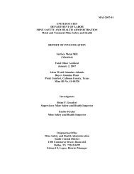
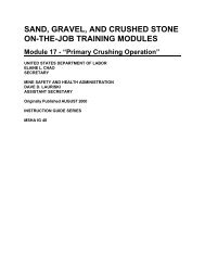
UNITED STATES DEPARTMENT OF LABOR<br />
MINE SAFETY AND HeALTH ADMINISTRATION<br />
PITTSBURGH SAFETY AND HEALTH TECHNOLOGY CENTER<br />
MINE WASTE AND GEOTECHNICAL ENGINEERING DIVISION<br />
COCHRANS MILL ROAD<br />
P.O. BOX 18233<br />
PITTSBURGH, PENNSYLVAN IA 15236<br />
REPORT NO. MW 11-005<br />
STRUCTURAL INVESTIGATION OF SURGE BIN TOWER COLLAPSE<br />
HILLTOP BASIC RESOURCES<br />
BIG BEND QUARRY<br />
MINE !.D. NO. 15-18147<br />
BATTLETOWN,MEADECOUNTY,KENTUCKY<br />
FEBRUARY 15,2011<br />
BY<br />
MICHAEL C. SUPERFESKY, P.E.<br />
CIVIL ENGINEER<br />
AND<br />
ANTHONY 1. ARGIRAKIS, E.I.T<br />
CIVIL ENGINEER
OWNERSHIP AND LOCATION<br />
REPORT NO. MWII-00S<br />
The Big Bend Quarry, <strong>Mine</strong> 1.0. No. 15-18147, is operated by Hilltop Basic Resources. The<br />
facil ity is located in Meade County, Kentucky, approximately 30 mi les southwest <strong>of</strong> Louisville,<br />
Kentucky. More precisely, the site has geographical coordinates 0[38°09'09" north latitude <strong>and</strong><br />
86°17'43" west longitude.<br />
INTRODUCTION<br />
The Big Bend Quany produces limestone from an open pit minc. The limestone is excavated by<br />
blasting <strong>and</strong> is run through a primary crusher in the pit before being transferred to the plant on<br />
the Overl<strong>and</strong> Conveyor. The Overl<strong>and</strong> Conveyor discharges into the 500-ton <strong>Surge</strong> <strong>Bin</strong> (photo<br />
1) in the plant area before additional crushing <strong>and</strong> sorting is pClformed. The material stored in<br />
the <strong>Surge</strong> <strong>Bin</strong> is mostly 4 to 6 inches in diameter, The Big Bend Quan·y employs 35 miners <strong>and</strong><br />
operates two shifts per day, 7 days a week.<br />
On Wednesday. November 10, 2010, at approximately 1:30 P.M., the 500-ton <strong>Surge</strong> <strong>Bin</strong> <strong>Tower</strong><br />
coll apsed. No injuries were sustained because no one was on or near the tower at the time <strong>of</strong> the<br />
collapse. An cye witness account <strong>of</strong> the collapse noted a sudden drop <strong>of</strong> the Overl<strong>and</strong><br />
Conveyor' s head pulley, which was mounted on the top <strong>of</strong> the bin, followed by toppling <strong>of</strong> the<br />
bin toward the Overl<strong>and</strong> Conveyor (west direction) (photo 2). The bin was at least one-half to<br />
three-quarters full <strong>and</strong> no material was being discharged into or out <strong>of</strong> the bin at the time <strong>of</strong> the<br />
collapse. On the day <strong>of</strong> the collapse, the wind speeds were low (10 MPH or less). Blasting in<br />
the pit (approximately II2-mile away) occurred 20 minutes before the bin collapsed. A<br />
seismograph located approximately II2-mile from the pit on residential property recorded a peak<br />
particle velocity below 0.0550 inches per second, which makes it is unlikely that the <strong>Surge</strong> <strong>Bin</strong><br />
<strong>Tower</strong> vibrated at a frequency which would have damaged the structure. The level <strong>of</strong> the<br />
limestone in the bin is usually monitored by cameras <strong>and</strong> a tilt switch. The tilt switch had<br />
malfunctioned a few days before the collapse. The camera provides only a live feed to the plant<br />
operator booth, it does not record.<br />
The collapse <strong>of</strong> the <strong>Surge</strong> <strong>Bin</strong> <strong>Tower</strong> removed the end support from the truss supporting the<br />
Overl<strong>and</strong> Conveyor. As a result. a 70-foot section <strong>of</strong> truss became partially detached, <strong>and</strong> was<br />
left hanging from the adjacent vertical bent support. The mine operator then proceeded to cut the<br />
belt <strong>and</strong> truss chords in order to bring the hanging section <strong>of</strong> the truss to the ground. The<br />
collapse <strong>of</strong> the <strong>Surge</strong> <strong>Bin</strong> <strong>Tower</strong> also damaged the tail <strong>of</strong> the Transfer Conveyor which was fed<br />
from the bottom <strong>of</strong> the bin on the east side. When the tail <strong>of</strong> the Transfer Conveyor was<br />
impacted, it caused the entire length <strong>of</strong> the Transfer Conveyor truss to thrust in the east direction,<br />
pennanently deflecting all <strong>of</strong> the bent supports to the east. The operator removed the truss <strong>and</strong><br />
conveyor components <strong>of</strong> the Transfer Conveyor while we were on site <strong>and</strong> intends on<br />
repairing/replacing the bents <strong>of</strong> the Transfer Conveyor.
FIELD INVESTIGATION<br />
2<br />
On November 15 through 18,2010, Michael Superfesky <strong>and</strong> Anthony Argirakis worked with<br />
Sonia Conway, Metal <strong>and</strong> Norunetal <strong>Safety</strong> <strong>and</strong> Health Inspector, Lexington Field Office, by<br />
providing assistance regarding the safe removal <strong>of</strong> the damaged conveyor <strong>and</strong> bin stlUcture. An<br />
additional40·foot <strong>of</strong> new conveyor truss was installed at the end <strong>of</strong>lhe Overl<strong>and</strong> Conveyor so<br />
that a stable cantilever was established until a new bin structure could be installed. Following<br />
the completion <strong>of</strong> this remedial work, the investigation <strong>of</strong> the <strong>Surge</strong> <strong>Bin</strong> <strong>Tower</strong> collapse<br />
commenced. The removal <strong>and</strong> installation <strong>of</strong> the new conveyor structure provided safe access to<br />
the area with little disturbance to the accident scene. A steady rain on November 16,2010, did<br />
produce a light coating <strong>of</strong> rust on the new fracture surfaces <strong>of</strong> the steel.<br />
MSHA was assisted during the investigation in collecting information <strong>and</strong> accessing the accident<br />
scene by the following Hilltop Basic Resources employees.<br />
John Morgan,<br />
Gary Lewis,<br />
Richard Popham,<br />
Kelly Carver,<br />
Configuration <strong>and</strong> Operation<br />
Vice President Mining Operations<br />
General Manager<br />
Quarry Manager<br />
Team Leader<br />
The <strong>Surge</strong> <strong>Bin</strong> <strong>Tower</strong> was configured with an overall height <strong>of</strong> 54 feet <strong>and</strong> square base 0[20.5<br />
feet per side. Photo 1 shows the <strong>Surge</strong> <strong>Bin</strong> <strong>Tower</strong> approximately 5 years prior to the collapse.<br />
The main structural members <strong>of</strong> the tower consisted <strong>of</strong> four columns with lateral bracing<br />
between the columns, a 2-level orthogonal arrangement <strong>of</strong>fIoor girders hung from the bin walls<br />
at the bottom, <strong>and</strong> stiffened bin walls which acted like plate girders (deep beams). The bin was<br />
square with interior dimensions <strong>of</strong> 20 feet by 20 feet <strong>and</strong> a height <strong>of</strong>28 feet. The bin was<br />
constructed by vertically stacking three prefabricated boxed sections (20 feet by 20 feet) together<br />
<strong>and</strong> bolting the box sections at each interface. The 3/4-inch-diameter bolts used for connecting<br />
tIle box sections were installed through the flange plates located on the top <strong>and</strong> bottom <strong>of</strong> each<br />
box section. The walls <strong>of</strong> each box section (bin walls) consisted <strong>of</strong> 1/4-ineh-thick steel plate<br />
stiffened on 2 foot centers using (non-bearing) steel angle sections with dimensions <strong>of</strong> 5 inches<br />
by 3 inches by 114 ineh. At the corners, the walls <strong>of</strong> the bin framed together at 90 degrees <strong>and</strong><br />
were connected using a 1/4-inch fillet weld placed on the inside. The comers <strong>of</strong> the bin were<br />
stiffened for bearing purposes by welding two vertical steel bars (plates) 6 inches by 114 inch at<br />
90 degrees to each other on the outside corners for the full 28-foot height <strong>of</strong> the bin. With<br />
respect to viewing the top <strong>of</strong> the bin from overhead, each corner <strong>of</strong> the bin, with the steel bar<br />
stiffeners attached, formed a cross. The attachment <strong>of</strong> the steel bar stiffeners to the bin corners<br />
helped in transferring the overall bin load (in bearing) to the columns below. The top <strong>of</strong> the<br />
columns had 3/4-inch-thick filler plates welded between both flanges on each side <strong>of</strong> the<br />
column's web to provide a bearing surface to connect the bottom <strong>of</strong> the bin corners <strong>and</strong> the bar<br />
stiffeners to the column. The bottom <strong>of</strong> the bin corners framed on top <strong>of</strong> the columns such that<br />
they interiorly rested upon one quarter <strong>of</strong> the total area provided by the filler plates <strong>and</strong> the<br />
column's web <strong>and</strong> flanges. Framing the bottom <strong>of</strong> the bin corner within an interior quadrant <strong>of</strong><br />
the column top allowed the steel bar stiffeners to be welded to the top <strong>of</strong> the column. The weld
etween the bottom comers <strong>of</strong> the bin <strong>and</strong> filler plates was the onJy connection between the bin<br />
<strong>and</strong> the columns, with the exception <strong>of</strong> the K-braces installed between the columns. The top <strong>of</strong><br />
the K-braces were attached to the undemeath side <strong>of</strong> the bin at midspan 011 all four sides <strong>of</strong> the<br />
bin. The primary purpose <strong>of</strong> the K-braces is to provide lateral support to the columns <strong>and</strong><br />
secondarily assist with the vertical bin load.<br />
There were three feeders located at the bottom <strong>of</strong> the bin in the center, east, <strong>and</strong> west sides.<br />
Wear or abrasion resistance plates were installed around the openings for the three feeders.<br />
There were no wear plates installed to protect <strong>and</strong> cushion the floor <strong>of</strong> the bin from impact <strong>and</strong><br />
abrasion, instead the operator had placed a 2-foot-thick layer or s<strong>and</strong>y-silt soil at the bottom <strong>of</strong><br />
the bin.<br />
3<br />
The bin rested above ground on four 17-foot-ta11 columns (WI2xI20) that were anchored to a<br />
rei nforced concrete footing using 3/4-inch diameter l-hooks embedded in the footing. The<br />
columns were laterally braced using K-braces on the north <strong>and</strong> south sides <strong>of</strong> the bin at both the<br />
upper <strong>and</strong> lower half <strong>of</strong> the columns with a horizontal brace between the two sets <strong>of</strong> K-braces.<br />
On the north <strong>and</strong> south sides <strong>of</strong> the bin, the columns were laterally braced in the east-west<br />
direction using K-bracing itl the upper half <strong>of</strong> the columns. Only the upper halves <strong>of</strong> the<br />
columns were bJ aced so that sufficient clearance existed on these sides for haulage trucks to pass<br />
under the bin. The center <strong>and</strong> west feeders <strong>of</strong> the bin were used very little during the life <strong>of</strong> the<br />
structure. The feeder on the east side <strong>of</strong> the bottom <strong>of</strong> the bin was the most active feeder because<br />
it was located above the tail <strong>of</strong> the Transfer Conveyor.<br />
The bottom flooring around the feeder openings consisted <strong>of</strong> 3/4-inch steel plates <strong>and</strong> two levels<br />
<strong>of</strong> orthogonally arranged W24x 1 04 girders. The 314-ineh steel plate fiooring was welded to the<br />
bottom flange <strong>of</strong> the top level <strong>of</strong> W24x: I 04 girders (running east to west) <strong>and</strong> was supported<br />
underneath by a second level <strong>of</strong> girders which were otiented in the north to south direction. In<br />
order to attach the 3/4-inch steel plate flooring to the bin walls, 114-inch fillet welds were<br />
implemented.<br />
The <strong>Surge</strong> <strong>Bin</strong> <strong>Tower</strong> was designed <strong>and</strong> constructed in 1999 by Process Machinery,<br />
Incorporated, Shelbyville, Kentucky. <strong>Report</strong>cdly, the bin was not actively used until 2006. Full<br />
usc <strong>of</strong> the bin began once the Overl<strong>and</strong> Conveyor, which feeds the Smge <strong>Bin</strong> from the pit <strong>and</strong><br />
the Transfer Conveyor was installed. PriOi to 2006, earth material surrounded the north, west,<br />
<strong>and</strong> east sides <strong>of</strong> the bin to fonn a ramp that equipment could drive up to in order to feed the top<br />
<strong>of</strong> a crusher located just to the east <strong>of</strong> the bin. When the crusher was removed, the earth ramp<br />
was also removed <strong>and</strong> the tail <strong>of</strong> the Transfer Conveyor was installed underneath the bin on the<br />
east side. Since the tail <strong>of</strong> Transfer Conveyor was installed underneath the bin on the east side,<br />
the corresponding feeder had been used fot discharging material out <strong>of</strong> the bin since 2006.<br />
The head pulley <strong>of</strong> the Overl<strong>and</strong> Conveyor was mounted on the top <strong>of</strong> the bin at the southwest<br />
comer <strong>and</strong> extended diagonally approximately 10 feet toward the center <strong>of</strong> the bin. It was<br />
reported that the discharge stream arced toward the east or Transfer Conveyor side <strong>of</strong> tbe bin<br />
where the east feeder was located. The height <strong>of</strong> stone on Ihe east side was lower than the west<br />
side due to the evacuation <strong>of</strong> material through the east side. Evacuation through the east feeder<br />
fonned a drawdown cone which intersected (flowed against) the east wall <strong>of</strong> the bin. The
4<br />
material on the three other sides <strong>of</strong> the bin was static. This type <strong>of</strong> flow discharge is refened to<br />
as asymmetric flow <strong>and</strong> is contrary to the desired condition <strong>of</strong> symmetric flow. Symmetric flow<br />
would have been occurring if the drawdown cone was symmetrically centered on the feeder<br />
located at the center <strong>of</strong> the bin. The symmetry <strong>of</strong> the position <strong>of</strong> the cone relative to the four<br />
walls <strong>of</strong> the bin causes the pressure to be unifol111ly applied to the walls <strong>and</strong> this helps to<br />
moderate the stresses in the bin walls. During asymmetric flow, the pressure along the bin walls<br />
is not unifonn because there are flow channels <strong>and</strong> static zones against the bin walls. This<br />
causes the stresses in the walls to fluctuate which can reduce the fatigue life <strong>of</strong> the bin.<br />
FindingS/Observations<br />
• The two top sections <strong>of</strong> the bin separated from the bottom section as they toppled (rotated 90<br />
degrees relative to the bottom section) toward the west in the direction <strong>of</strong> the Overl<strong>and</strong><br />
Conveyor. The movement <strong>of</strong> the bottom section <strong>of</strong> the bin was also to the west. The west<br />
side <strong>of</strong> the bottom section <strong>of</strong> the bin came to rest in a lower position than that <strong>of</strong> the east side<br />
(photo 2). This indicates that the underneath <strong>of</strong> the west side <strong>of</strong> the bin "fell out from<br />
underneath" or "gave-way" prior to the east side. It is believed that the loss <strong>of</strong> support on the<br />
west side <strong>of</strong> the bin was caused by the failure <strong>of</strong> the columns (excessive bending or<br />
buckling).<br />
• Photo 3, which is the interior portion <strong>of</strong> the Transfer Conveyor (east) side <strong>of</strong> the bin, shows<br />
abrasive markings on thc wall that the material discharging from the bin would flow against.<br />
These markings were only present on the east side <strong>of</strong> the bin <strong>and</strong> this indicates that the<br />
drawdown cone <strong>of</strong> the discharge flow was <strong>of</strong>fset from the central interior <strong>of</strong> the bin<br />
(asymmetric flow).<br />
• The columns on the Overl<strong>and</strong> Conveyor side (west side) <strong>of</strong> the bin were significantly bent or<br />
buckled. This is an iudication that the load carrying capacities <strong>of</strong> the columns were<br />
exceeded. Since the bin was not overloaded at the time <strong>of</strong> the collapse, <strong>and</strong> the columns<br />
were not deficient from weathering/corrosion, a shift or a deviation in the manner in which<br />
the columns were loaded would have had to occur to cause them to buckle. When the load<br />
applied to a column is not concentric to its long axis, the loading becomes eccentric (applied<br />
from a distance), <strong>and</strong> this creates a bending moment (force with a lever arm) on top <strong>of</strong> the<br />
column which makes it easier for the colunm to buckle. Fatigue cracks or corrosion at the<br />
bin comers would have reduced the structural rigidity at the bin comers <strong>and</strong> caused the load<br />
from the bin to be applied at some distance away from the geometric center <strong>of</strong> the column.<br />
Also, it is possible that the bin walls or connections at the comers themselves locally failed<br />
(fractured or compressed) causing the bin to detach from the column connection. Once the<br />
bin dctached from one <strong>of</strong> the columns at a corner, the bin would have then sat down on that<br />
column <strong>and</strong> loaded it eccentrically causing the column to buckle.<br />
• Vertical fractures along the west side corners <strong>of</strong>lhe bottom section <strong>of</strong>lhe bin (photo 3) were<br />
resulting damage from the collapse. The fracturing occurred through the thickness <strong>of</strong> the bin<br />
walls <strong>and</strong> not in the vertical welds which fastened the comers <strong>of</strong> the bin walls.<br />
Measurements laken along these vertical tears indicated that the loss <strong>of</strong> wall thick.ness from<br />
corrosion at these fracture surfaces was less than 5 percent. These fractures are not believed
5<br />
to be the cause <strong>of</strong> the failure, bUL are a secondary effect <strong>of</strong> the failure. Tn order for the two<br />
top box sections <strong>of</strong> the bin to topple over, they had to break free from the bottom section, <strong>and</strong><br />
they did this by tearing the west side comers <strong>of</strong> the bottom section.<br />
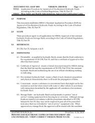
• Fracturing/detachment <strong>of</strong> the bottom <strong>of</strong> the bin occurred at the top <strong>of</strong> all four columns. It<br />
appears that most <strong>of</strong> the fracturing <strong>of</strong> the bin attachment to the top <strong>of</strong> the east side columns<br />
was caused after the tower became unstable. For example, photos 4 <strong>and</strong> 5 shows the top <strong>of</strong><br />
the east side columns where portions <strong>of</strong> the bin wall <strong>and</strong> corner stiffening plateslbars<br />
fractured. The majority <strong>of</strong> the deformation <strong>and</strong> the fracturing observed in photos 4 <strong>and</strong> 5 are<br />
believed to be the result <strong>of</strong> the pulling away <strong>of</strong>the bin walls from the columns when the bin<br />
shifted <strong>and</strong> fell to the west. The bin also disconnected from the west side colmnns. Photo 6<br />
shows the portion <strong>of</strong> the bin wall remaining on the top <strong>of</strong> the southwest column <strong>and</strong> how the<br />
portion <strong>of</strong> the bin wall remaining on the top <strong>of</strong> the column was bent <strong>and</strong> pulled down below<br />
the top <strong>of</strong> the column. Photo 7 shows the portion <strong>of</strong> the bin wall remaining on top <strong>of</strong> the<br />
northwest column <strong>and</strong> the crimping <strong>of</strong> the bin wall above the colunm. The crimping could<br />
have occuned because <strong>of</strong> a compressive failure in the bin wall itself or because <strong>of</strong> lateral<br />
deflection which would have accompanied the buckling <strong>of</strong> the column. The fracture surfaces<br />
<strong>of</strong> the remnants <strong>of</strong> the bin wall attached to the top <strong>of</strong> the columlls did not appear depleted or<br />
damaged from corrosion. With respect to the COIUlrulS on the west side, the small amount <strong>of</strong><br />
bin wall that was remaining attached to the top <strong>of</strong> the columns shows the load transfer<br />
between the columns <strong>and</strong> bin was occurring over a small area. Smaller areas <strong>of</strong>load transfer<br />
will create greater stresses in that area. Higher stresses led to a greater chance that a fracture<br />
will occur.<br />
• Upward bending or prying was fo und at the comers <strong>of</strong> the bin floor at the west side columns<br />
(photo 8). This deformation is indicative <strong>of</strong> excessive bending or rotational loading being<br />
transferred between the west columns <strong>and</strong> the comer <strong>of</strong> the flooring. There are two<br />
behaviors that may have produced this defonnation. The first would result from the bending<br />
or buckling <strong>of</strong> the west side columns themselves. As the columns excessively bentlbuckled,<br />
the bending load at the top <strong>of</strong> the column would have increased causing such deformation.<br />
The second mode <strong>of</strong> behavior is that if there was a loss <strong>of</strong> stiffness or rigidity where the bin<br />
attached to the east side columns, the west side colwnns would be req uired to carry more <strong>of</strong><br />
the bin load. This would result in the structure momentarily behaving as a cantilever beam<br />
with the east end free or not supported, <strong>and</strong> all <strong>of</strong> the load would be forced to go to the west<br />
side, producing the deformation observed at the west comers.<br />
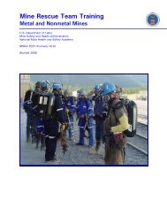
• A final major deformational characteristic, which is not believed to be direct cause <strong>of</strong> the<br />
collapse, was that the base <strong>of</strong> all four columns had pulled free (uprooted) from the concrete<br />
foundation that they were anchored upon (photo 9). It appears that the base <strong>of</strong> the east side<br />
columns pulled free after the initial trigger <strong>of</strong> the failure. After the bin detached from the top<br />
<strong>of</strong> the east side columns, the bottom section <strong>of</strong> the bin slid down against the columns, <strong>and</strong><br />
this applied a lever action to the top <strong>of</strong> the columns which uprooted the columns. It is<br />
believed that both west side columns were pried free from the foundation during the action <strong>of</strong><br />
the columns buckling. The extreme deformations <strong>of</strong> a column during buckling are conducive<br />
for allowing the column to act like a lever <strong>and</strong> pry itself free from the foundation.
Failure Discussion<br />
6<br />
The collapse <strong>of</strong> the <strong>Surge</strong> <strong>Bin</strong> <strong>Tower</strong> occurred because the columns on the Overl<strong>and</strong> Conveyor<br />
side <strong>of</strong> the tower buckled. Since the columns were in good condition <strong>and</strong> the bin was not<br />
overloaded. there had to be a change in the marU1cr that the bin was loading the columns for them<br />
to fail as they did. It is thought that the change to the way the columns were being loaded<br />
resulted from loss <strong>of</strong> rigidity at the bin-ta-column connection or at the bottom <strong>of</strong> the bin corners<br />
because <strong>of</strong> corrosion <strong>and</strong>/or fatigue. There was corrosion at the bottom <strong>of</strong> the bin wall corners<br />
where the columns were loaded. Additionally, the stresses <strong>and</strong>lor fluctuation <strong>of</strong> the stresses at<br />
the corner <strong>of</strong> the bin could have been larger than the design anticipated because asymmetric flow<br />
<strong>of</strong> material was occurring in the bin. Generally, when any type <strong>of</strong> bin (circular or rectangular) is<br />
operated undcr asymmetric flow there are areas in the bin wall where the stresses will increase<br />
<strong>and</strong>/or fluctuate because the material within the bin is n01 pressing against the bin walls equally<br />
at all locations. Corrosion <strong>and</strong> fluctuation <strong>of</strong> stresses would make the comers <strong>of</strong> the bin<br />
susceptible to fatigue cracking. Cracking from fatigue (loading <strong>and</strong> unloading <strong>of</strong> the bin) would<br />
have lessened the structural rigidity at the corners <strong>of</strong> the tower where the bin loads the columns.<br />
A weakened bin comer or bin-to-column cOlmection could have deflected, fractured, or wrinkled<br />
<strong>and</strong> this would have changed the load path between the bin comers <strong>and</strong> the columns below. It<br />
would only take loss <strong>of</strong> structural rigidity at one <strong>of</strong> the bin-to-column cOlIDcctions to initiate the<br />
collapse, because the bin would shift <strong>of</strong>f from the center <strong>of</strong> the columns <strong>and</strong> eccentrically load<br />
them. Eccentric loading is loading that is not concentric with the columns longitudinal axis <strong>and</strong><br />
thus puts additional stresses in the column which can cause buckling. Once column buckling<br />
occurred, the bin was no longer vertically supported in a stable manner <strong>and</strong> additional shifting <strong>of</strong><br />
the bin <strong>and</strong> its load caused damage to other columns <strong>and</strong> structural members resulting in the<br />
complete collapse <strong>of</strong> the Lower.<br />
Incidental Inspection/Repair Item<br />
It was observed that the base orthe legs <strong>of</strong> the A-frame bent closest to the <strong>Surge</strong> <strong>Bin</strong> <strong>Tower</strong> <strong>of</strong><br />
the Overl<strong>and</strong> Conveyor has been impacted by equipment (photo 10). The base <strong>of</strong> the column<br />
should be repaired. The repair call be accomplished by installing/fitting a chalIDel or angle steel<br />
sections within the interior <strong>of</strong> the columns so that they rest against the web <strong>and</strong> flanges <strong>of</strong> the<br />
existing column sections. This repair should be done for both legs <strong>of</strong> the bent.<br />
CONCLUSIONS AND RECOMMENDATIONS<br />
The <strong>Surge</strong> <strong>Bin</strong> <strong>Tower</strong> collapsed because the columns on the side <strong>of</strong> the Overl<strong>and</strong> Conveyor<br />
became eccentrically loaded which caused the columns to buckle. The column failure was most<br />
likely initiated by the bin load not being properly tlansferrcd to the top <strong>of</strong> columns because the<br />
bottom <strong>of</strong> the bin comers or the bin-to-column connection experienced a reduction ill structural<br />
rigidity caused by corrosion <strong>and</strong>/or fatigue damage. Corrosion <strong>of</strong> the bin walls above the<br />
columns <strong>and</strong> large <strong>and</strong>/or fluctuating stresses at the bin comer from asymmetric flow made the<br />
bin comers <strong>and</strong> their connection to the columns vulnerability to fatigue cracking. Fatigue <strong>and</strong>/or<br />
corrosion damage caused a loss in structural rigidity at the bin comers <strong>and</strong> their connection to the
7<br />
columns which most likely initiated an unstable or eccentric loading on the bin columns on the<br />
Overl<strong>and</strong> Conveyor side <strong>of</strong> the tower which led to sudden buckling <strong>of</strong> the columns <strong>and</strong> collapse<br />
<strong>of</strong> the structure.<br />
Another finding <strong>of</strong> this investigation was that the bin structure was marginally adequate at the<br />
four comers to transfer the bin load to the columns. Additional stiffening <strong>of</strong> the bin walls,<br />
comers, <strong>and</strong> the bin-la-column weld cOimection would have enhanced the structural rigidity <strong>and</strong><br />
prevented load concentration <strong>and</strong> vulnerability to fatigue via corrosion, shock, <strong>and</strong> vibration. If<br />
additional stiffening members had been installed at the bottom <strong>of</strong> the bin comers where they<br />
connected to the columns, it is thought that this would have strengthened this area <strong>and</strong> spread the<br />
load transfer path out so that more <strong>of</strong> the bin wall was required to carry the load, <strong>and</strong> this would<br />
have reduced the stresses <strong>and</strong> vulnerability to failure.<br />
If this same exact bin lOwer configuration is installed at the subject site as a replacement, it is<br />
recommended that the bin corner/column load transfel system <strong>of</strong> this structure be analyzed in<br />
more detail by the engineer providing the design to ensure that the potential vulnerability <strong>of</strong><br />
fatigue or overstress has been properly addressed. As a temporary <strong>and</strong> minimum safety measure,<br />
it is recommended tbat a structural steel section such as an equal leg angle be welded <strong>and</strong> fitted<br />
against the four bin corners for the full height <strong>of</strong> the bottom section <strong>of</strong> the bin. A second part <strong>of</strong><br />
this stiffening measure is to install an equal leg angle at an inclination between 45 <strong>and</strong> 70<br />
degrees from the bottom <strong>of</strong> the bin on each side <strong>of</strong> the comers <strong>of</strong> the bin walls between the<br />
comers <strong>and</strong> the vertical wall stiffener nearest the corner. Also, considering that this type <strong>of</strong> bin<br />
structure may exist at other mining operations, operators with this exact bin tower configuration<br />
should be informed <strong>of</strong> this situatiOn/condition, <strong>and</strong> based upon the recommendation <strong>of</strong> their<br />
engineer. appropriate stiffening to the bin corners should be made.<br />
<strong>Report</strong> Prepared by:<br />
Michael C. Superfesky. P.E.<br />
Civil Engineer<br />
<strong>Report</strong> Approved by:<br />
Antho . Argirakis. E.l.T.<br />
Civil Engineer
Photo I - East side <strong>of</strong> <strong>Surge</strong> <strong>Bin</strong> <strong>Tower</strong> during the year 2006.<br />
Htad 01 Overl.nd<br />
Conveyor<br />
(West SIde)<br />
Photo 2 - South side <strong>of</strong> <strong>Surge</strong> <strong>Bin</strong> Towel with respect to looking north.
R,mnlnt <strong>of</strong> 811'1<br />
Will Attach" to<br />
Top <strong>of</strong> Column<br />
Aft.r Frlctur'<br />
Photo 5 - Top <strong>of</strong> Southeast column following the collapse.<br />
Photo 6 - Buckled shape <strong>of</strong> southwest coiunm <strong>of</strong>the bin following collapse.
Photo 9 - Base <strong>of</strong> northeast colwnn uprooted from the footing.<br />
_ ,'t<br />
- ,<br />
.. . ;<br />
.' ". .<br />
"<br />
"<br />
-<br />
i -<br />
Photo 10 - Base <strong>of</strong> north leg <strong>of</strong> A-frame bent closest to <strong>Surge</strong> <strong>Bin</strong> <strong>Tower</strong>.