SG-SRT Datasheet - Datasensor
SG-SRT Datasheet - Datasensor
SG-SRT Datasheet - Datasensor

Create successful ePaper yourself
Turn your PDF publications into a flip-book with our unique Google optimized e-Paper software.
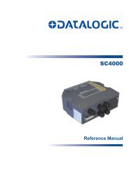
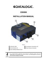
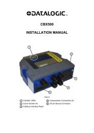
safety accessories<br />
SAFETY LIGHT CURTAINS<br />
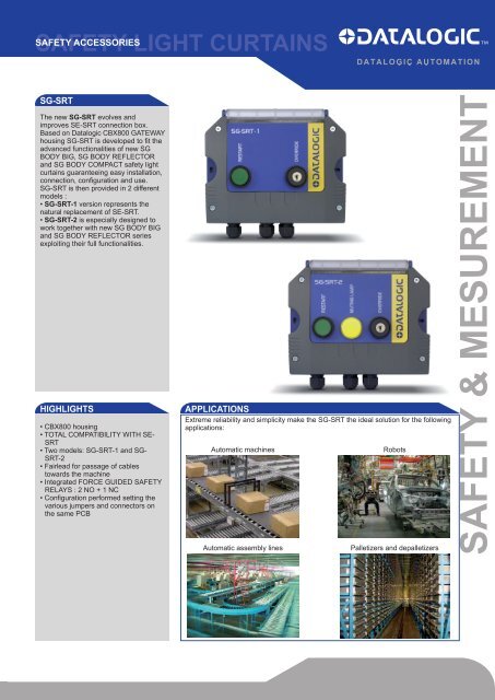
<strong>SG</strong>-<strong>SRT</strong><br />
The new <strong>SG</strong>-<strong>SRT</strong> evolves and<br />
improves SE-<strong>SRT</strong> connection box.<br />
Based on Datalogic CBX800 GATEWAY<br />
housing <strong>SG</strong>-<strong>SRT</strong> is developed to fit the<br />
advanced functionalities of new <strong>SG</strong><br />
BODY BIG, <strong>SG</strong> BODY REFLECTOR<br />
and <strong>SG</strong> BODY COMPACT safety light<br />
curtains guaranteeing easy installation,<br />
connection, configuration and use.<br />
<strong>SG</strong>-<strong>SRT</strong> is then provided in 2 different<br />
models :<br />
• <strong>SG</strong>-<strong>SRT</strong>-1 version represents the<br />
natural replacement of SE-<strong>SRT</strong>.<br />
• <strong>SG</strong>-<strong>SRT</strong>-2 is especially designed to<br />
work together with new <strong>SG</strong> BODY BIG<br />
and <strong>SG</strong> BODY REFLECTOR series<br />
exploiting their full functionalities.<br />
HIGHLIGHTS<br />
• CBX800 housing<br />
• TOTAL COMPATIBILITY WITH SE-<br />
<strong>SRT</strong><br />
• Two models: <strong>SG</strong>-<strong>SRT</strong>-1 and <strong>SG</strong>-<br />
<strong>SRT</strong>-2<br />
• Fairlead for passage of cables<br />
towards the machine<br />
• Integrated FORCE GUIDED SAFETY<br />
RELAYS : 2 NO + 1 NC<br />
• Configuration performed setting the<br />
various jumpers and connectors on<br />
the same PCB<br />
APPLICATIONS<br />
Extreme reliability and simplicity make the <strong>SG</strong>-<strong>SRT</strong> the ideal solution for the following<br />
applications:<br />
Automatic machines<br />
Automatic assembly lines<br />
Robots<br />
Palletizers and depalletizers<br />
SAFETY & MESUREMENT
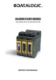
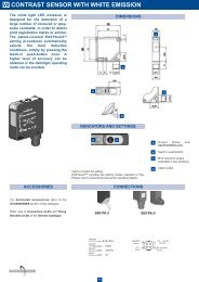
DIMENSIONS<br />
82.3<br />
[3.24]<br />
156.8<br />
[6.17]<br />
84.3<br />
[3.32]<br />
96<br />
[3.78]<br />
71.7<br />
[2.82]<br />
176.0<br />
[6.93]<br />
4.0<br />
[0.16]<br />
4.0<br />
[0.16]<br />
Ø4.3<br />
[Ø0.17]<br />
181<br />
[7.13]<br />
192<br />
[7.58]<br />
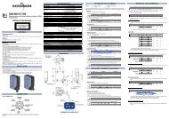
ELECTRICAL CONNECTIONs<br />
M5<br />
J1<br />
J2<br />
M1<br />
M4<br />
J5<br />
J3<br />
J4<br />
M2<br />
M3<br />
www.automation.datalogic.com
CONFIGURATION SELECTIONS<br />
JUMPER FUNCTION POS SELECTION DEFAULT<br />
J1<br />
RESTART<br />
1-2 AUTOMATIC RESTART (*) X<br />
2-3 MANUAL RESTART<br />
j2<br />
LAMP<br />
1-2 LAMP ON BOX (**) X<br />
2-3 EXTERNAL LAMP<br />
j3<br />
OSSD2<br />
1-2 RLY2 RELAY ENABLED X<br />
2-3 OSSD2 ROUTED TO OUT<br />
j4<br />
OSSD1<br />
1-2 RLY1 RELAY ENABLED X<br />
2-3 OSSD1 ROUTED TO OUT<br />
j5<br />
EDM<br />
1-2 EDM INTERNAL X<br />
2-3 EDM EXTERNAL<br />
(*) FORCED CONFIGURATION FOR <strong>SG</strong>BODY COMPACT (the selection of the Restart should be determined by the appropriate light curtain DIPswitches)<br />
(**) ONLY FOR <strong>SG</strong>-<strong>SRT</strong>-2 MODELS<br />
CONN. Pin DESCRIPTION<br />
M1 1 K111 PIN 1 RLY1 - 1°CONTACT<br />
2 K112 PIN 2 RLY1 - 1°CONTACT<br />
3 K121 PIN 1 RLY1 - 2°CONTACT<br />
4 K122 PIN 2 RLY1 - 2°CONTACT<br />
5 K211 PIN 1 RLY2 - 1°CONTACT<br />
6 K212 PIN 2 RLY2 - 1°CONTACT<br />
7 K221 PIN 1 RLY2 - 2°CONTACT<br />
8 K222 PIN 2 RLY2 - 2°CONTACT<br />
M2 1 VCC TX Unit<br />
2 GND TX Unit<br />
3 FE TX Unit - not present on <strong>SG</strong> BODY COMPACT-<br />
4 TEST TX Unit - not present on <strong>SG</strong> BODY COMPACT-<br />
M3 1 VCC 24 VCC INPUT<br />
2 GND GND INPUT<br />
3 OSSD2 OUT 2<br />
4 OSSD1 OUT 1<br />
5 EDM OUT EDM<br />
6 MUTING E MUTING ENABLE INPUT<br />
7 LAMP OUT EXTERNAL LAMP OUT<br />
8 OVR STAT OVERRIDE STATUS OUT<br />
9 FE FUNCTIONAL EARTH GROUND<br />
10 TEST TEST<br />
M4 1 VCC RX Unit<br />
2 GND RX Unit<br />
3 RESTART RX Unit<br />
4 OVR1 RX Unit<br />
5 OSSD2 RX Unit<br />
6 EDM RX Unit<br />
7 MUTING E RX Unit - not present on <strong>SG</strong> BODY COMPACT-<br />
8 OSSD1 RX Unit<br />
9 OVR2 RX Unit<br />
10 LAMP RX Unit - not present on <strong>SG</strong> BODY COMPACT-<br />
11 OVE STAT RX Unit - not present on <strong>SG</strong> BODY COMPACT-<br />
12 FE RX Unit - not present on <strong>SG</strong> BODY COMPACT-<br />
M5 1 M51 TO RESTART PUSHBUTTON<br />
2 M52 TO RESTART PUSHBUTTON<br />
3 M53 TO GND LAMP OF RESTART PUSH BUTTON<br />
4 M54 TO LAMP OF RESTART PUSH BUTTON<br />
5 M55 TO OVERRIDE OVR1 PUSH BUTTON<br />
pre-wired<br />
6 M56 TO 24 VCC OVERRIDE OVR1 PUSH BUTTON<br />
7 M57 TO OVERRIDE OVR2 PUSH BUTTON<br />
8 M58 TO GND OVERRIDE OVR2 PUSH BUTTON<br />
9 M59 TO TEST LAMP<br />
10 M510 TO VCC OF TEST LAMP
FUNCTIONING<br />
The <strong>SG</strong>-<strong>SRT</strong> connection boxes allow you to directly manage, without further action, the following functions according to the typical<br />
operation of the connected Safety Barrier model:<br />
FUNCTION<br />
TEST<br />
RESTART<br />
RESET<br />
EDM internal<br />
EDM external actuators<br />
OVERRIDE<br />
MUTING STATE<br />
THROUGH<br />
TEST/START Push button<br />
TEST/START Push button<br />
TEST/START Push button<br />
Internal Selector<br />
Internal Selector<br />
Key Selector<br />
Integrated Lamp (<strong>SG</strong>-<strong>SRT</strong>-2 only)<br />
Please refer to the Safety Barrier Manuals for all information regarding connections, operations and options for the functions listed<br />
above.<br />
OUTPUT RELAY BEHAVIOUR<br />
The boxes use 2 safety guided relay contacts. These relays are specified by the manufacturer for higher voltages and currents as<br />
indicated by the technical data.<br />
However, to ensure correct isolation and prevent premature damage for age drift, you need to protect each output line using a delayed<br />
6A fuse and verify that the load characteristics comply with the instructions below:<br />
Max. switchable voltage: 250 Vac<br />
Max. switchable current: 2 A<br />
CONNECTION BOX AND SAFETY LIGHT CURTAIN CORRESPONDENCE<br />
SAFETY LIGH CURTAIN MODEL<br />
CONNECTION BOX MODEL<br />
<strong>SG</strong>2 BODY COMPACT BASE -<br />
<strong>SG</strong>2 BODY COMPACT MUTING<br />
<strong>SG</strong>-<strong>SRT</strong>-1<br />
<strong>SG</strong>4 BODY COMPACT BASE -<br />
<strong>SG</strong>4 BODY COMPACT MUTING<br />
<strong>SG</strong>-<strong>SRT</strong>-1<br />
<strong>SG</strong>2 BODY BIG BASE -<br />
<strong>SG</strong>2 BODY BIG MUTING<br />
<strong>SG</strong>-<strong>SRT</strong>-1 / <strong>SG</strong>-<strong>SRT</strong>-2<br />
<strong>SG</strong>4 BODY BIG BASE -<br />
<strong>SG</strong>4 BODY BIG MUTING<br />
<strong>SG</strong>-<strong>SRT</strong>-1 / <strong>SG</strong>-<strong>SRT</strong>-2<br />
<strong>SG</strong>4 BODY REFLECTOR BASE -<br />
<strong>SG</strong>4 BODY REFLECTOR MUTING<br />
<strong>SG</strong>-<strong>SRT</strong>-1 / <strong>SG</strong>-<strong>SRT</strong>-2<br />
MODEL SELECTION AND ORDER INFORMATION<br />
MODEL DESCRIPTION ORDER N°<br />
<strong>SG</strong>-<strong>SRT</strong>-1 <strong>SG</strong>-<strong>SRT</strong>-1 MUTING CONNECTION BOX 95ASE2050<br />
<strong>SG</strong>-<strong>SRT</strong>-2 <strong>SG</strong>-<strong>SRT</strong>-2 MUTING CONNECTION BOX LAMP 95ASE2060<br />
UNI EN ISO9001<br />
The company endeavours to continuously improve and renew its products; for this reason the technical data and contents of this catalogue may undergo<br />
variations without prior notice. For correct installation and use, the company can guarantee only the data indicated in the instruction manual supplied with the<br />
products.<br />
Rev. 0 08/2011<br />
www.automation.datalogic.com