INSTALLATION INSTRUCTIONS Râ410A Ductless Split System Air ...
INSTALLATION INSTRUCTIONS Râ410A Ductless Split System Air ...
INSTALLATION INSTRUCTIONS Râ410A Ductless Split System Air ...

Create successful ePaper yourself
Turn your PDF publications into a flip-book with our unique Google optimized e-Paper software.
<strong>INSTALLATION</strong> <strong>INSTRUCTIONS</strong><br />
R−410A <strong>Ductless</strong> <strong>Split</strong> <strong>System</strong>: DLF4(A/H), DLC4(A/H)<br />
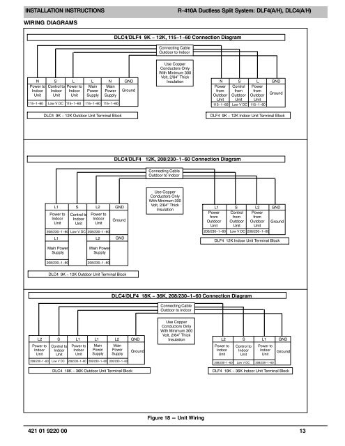
WIRING DIAGRAMS<br />
DLC4/DLF4 9K − 12K, 115−1−60 Connection Diagram<br />
Connecting Cable<br />
Outdoor to Indoor<br />
N S L L N GND<br />
Power to Control to Power to Main Main<br />
Indoor<br />
Unit<br />
Indoor<br />
Unit<br />
Indoor<br />
Unit<br />
Power<br />
Supply<br />
Power<br />
Supply<br />
Ground<br />
115−1−60<br />
Low V DC<br />
Use Copper<br />
Conductors Only<br />
With Minimum 300<br />
Volt, 2/64” Thick<br />
Insulation<br />
N S L GND<br />
Power Control Power<br />
from<br />
Outdoor<br />
from<br />
Outdoor<br />
from<br />
Outdoor<br />
Ground<br />
Unit Unit Unit<br />
115−1−60 115−1−60 115−1−60 115−1−60 Low V DC 115−1−60<br />
DLC4 9K − 12K Outdoor Unit Terminal Block<br />
DLF4 9K − 12K Indoor Unit Terminal Block<br />
DLC4/DLF4 12K, 208/230−1−60 Connection Diagram<br />
Connecting Cable<br />
Outdoor to Indoor<br />
L1<br />
Power to<br />
Indoor<br />
Unit<br />
S<br />
Control to<br />
Indoor<br />
Unit<br />
L2<br />
Power to<br />
Indoor<br />
Unit<br />
208/230−1−60 Low V DC 208/230−1−60<br />
GND<br />
Ground<br />
Use Copper<br />
Conductors Only<br />
With Minimum 300<br />
Volt, 2/64” Thick<br />
Insulation<br />
L1<br />
Power<br />
from<br />
Outdoor<br />
Unit<br />
208/230−1−60<br />
S<br />
Control<br />
from<br />
Outdoor<br />
Unit<br />
L2<br />
Power<br />
from<br />
Outdoor<br />
Unit<br />
Low V DC 208/230−1−60<br />
GND<br />
Ground<br />
L1<br />
L2<br />
GND<br />
DLF4 12K Indoor Unit Terminal Block<br />
Main Power<br />
Supply<br />
Main Power<br />
Supply<br />
208/230−1−60<br />
208/230−1−60<br />
DLC4 9K − 12K Outdoor Unit Terminal Block<br />
DLC4/DLF4 18K − 36K, 208/230−1−60 Connection Diagram<br />
Connecting Cable<br />
Outdoor to Indoor<br />
L2 S L1 L1 L2 GND<br />
Power to<br />
Indoor<br />
Unit<br />
Control to<br />
Indoor<br />
Unit<br />
Power to<br />
Indoor<br />
Unit<br />
Main<br />
Power<br />
Supply<br />
Main<br />
Power<br />
Supply<br />
208/230−1−60 Low V DC 208/230−1−60 208/230−1−60 208/230−1−60<br />
DLC4 18K − 36K Outdoor Unit Terminal Block<br />
Ground<br />
Use Copper<br />
Conductors Only<br />
With Minimum 300<br />
Volt, 2/64” Thick<br />
Insulation<br />
L2 S L1 GND<br />
Power to<br />
Indoor<br />
Unit<br />
Control to<br />
Indoor<br />
Unit<br />
Power to<br />
Indoor<br />
Unit<br />
208/230−1−60 Low V DC 208/230−1−60<br />
Ground<br />
DLF4 18K − 36K Indoor Unit Terminal Block<br />
Figure 18 - Unit Wiring<br />
421 01 9220 00 13