INvERTER SERIES V1000
INvERTER SERIES V1000
INvERTER SERIES V1000

You also want an ePaper? Increase the reach of your titles
YUMPU automatically turns print PDFs into web optimized ePapers that Google loves.
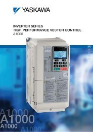
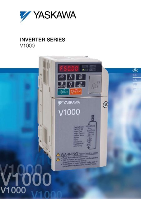
Inverter Series<br />
<strong>V1000</strong><br />
EN<br />
DE<br />
ES<br />
FR<br />
IT<br />
1000<br />
<strong>V1000</strong><br />
<strong>V1000</strong><br />
<strong>V1000</strong><br />
<strong>V1000</strong>
<strong>V1000</strong><br />
YASKAWA Inverter Drive Technology<br />
Contents<br />
Page 2<br />
Experience & Innovation<br />
A leader in Inverter Drives<br />
technology<br />
<strong>V1000</strong> – Easy and cost-saving<br />
handling through all kinds of<br />
applications<br />
Page 3<br />
”One for all“ –<br />
Multiple Applications<br />
Page 4/5<br />
Specifications<br />
Page 6<br />
Connection Diagram<br />
Content Page 7<br />
<strong>V1000</strong> Dimensions<br />
Experience & Innovation<br />
For more than 90 years YASKAWA has<br />
been manufacturing and supplying<br />
mechatronic products for machine<br />
building and industrial automation. Its<br />
standard products as well as tailor-made<br />
solutions are famous and have a high<br />
reputation for outstanding quality and<br />
durability.<br />
A leader in Inverter Drives<br />
technology<br />
Extensive research and development has<br />
allowed YASKAWA to remain at the forefront<br />
of motion control and automation technology.<br />
This technological leadership has helped<br />
to modernise industries such as mining,<br />
steel, pulp and paper, chemical, automotive,<br />
packaging, machine tool and semiconductor.<br />
focuses on all aspects of application,<br />
installation, operation and maintenance.<br />
Safety Integrated<br />
YASKAWA <strong>V1000</strong> is one of the first general<br />
purpose compact drives with built-in two<br />
channel hardware base block input. It already<br />
meets international safety standards and<br />
thereby supports machine builder to apply<br />
to international machine directives.<br />
Finless Type<br />
YASKAWA has as one of the first<br />
manufacturers promoted the development<br />
of finless type inverters for the European<br />
and international markets. Consequently the<br />
<strong>V1000</strong> is available as finless version for<br />
applications with an external cooling system.<br />
YASKAWA <strong>V1000</strong> Features<br />
Page 8<br />
<strong>V1000</strong> Finless Version<br />
Dimensions<br />
Page 9<br />
<strong>V1000</strong> IP66 Dimensions<br />
Page 10<br />
Options<br />
Page 11<br />
Ratings & Type Descriptions<br />
incl. finnless<br />
In 2007 YASKAWA produced its 10 millionth<br />
inverter in the new inverter plant in<br />
Yukuhashi, Japan. By this YASKAWA is<br />
probably the biggest inverter manufacturer in<br />
the world.<br />
The 10 millionth inverter was a <strong>V1000</strong>, the<br />
latest inverter developed by YASKAWA.<br />
Awarded by IEN magazine as being the<br />
‘most innovative product 2007’ at Hanover<br />
Fair Industry 2007 the <strong>V1000</strong> has raised the<br />
bar in the market in terms of usability and<br />
reliability.<br />
<strong>V1000</strong> – Easy and cost-saving<br />
handling through all kinds of<br />
applications<br />
This powerful little helper sets standards<br />
in terms of user friendliness and process<br />
orientation. The development of the <strong>V1000</strong><br />
Dual Safety Input, safety category 3<br />
(EN954-1) and stop category 0<br />
(EN60204-1) and IEC-61508 SIL2<br />
In normal duty (120% overload) one<br />
frame size larger motor can be driven<br />
Standard AC Motor and PM motor control<br />
V/f and open-loop current<br />
vector control<br />
One of the smallest inverter drives<br />
in the world<br />
Side-by-side mounting<br />
Icon-based programming<br />
Designed for 10 years of<br />
maintenance-free operation<br />
2 YASKAWA <strong>V1000</strong>
“One for all” – Multiple Applications<br />
YASKAWA <strong>V1000</strong> is a general purpose inverter drive covering the demands of a wide field of applications.<br />
Simple duties as well as requirements of complex systems need a higher level of functionality, reliability and easy handling,<br />
which are provided by the <strong>V1000</strong>.<br />
For energy saving, permanent magnet motor control is possible<br />
Selectable control method: open-loop current vector or V/f<br />
Small Design – Big Power: 150% overload in heavy duty service is possible. For applications with low overload<br />
requirements the drive can be operated with 120% overload in normal duty service. Consequently you can use a drive of<br />
smaller size to do the work of a bigger one.<br />
Worldwide specification CE, UL, cUL, RoHS (TÜV safety approved)<br />
High flux braking reduces braking time to the half<br />
Easy Installation<br />
Reliable Operation<br />
YASKAWA <strong>V1000</strong> reduces installation time and costs. Installable in tight<br />
spaces it requires a minimum of set-up time and provides you all the<br />
comfort of a modern up-to-date inverter drive.<br />
One of the smallest inverter drives in the world saves mounting<br />
space and cost by side-by-side mounting<br />
Application parameter pre-settings shorten set-up time<br />
Same handling and parameter structure for all YASKAWA inverters<br />
DriveWorksEZ visual programming tool. Simply drag and drop icons<br />
to customize your drive. Create special sequences and detection<br />
functions, then load them onto the drive.<br />
Quick Maintenance<br />
The <strong>V1000</strong> continues the tradition of YASKAWA by being the reliable<br />
link in your production chain.<br />
Designed for Long Performance Life (10 years 24 h per day at 80%<br />
nominal load.)<br />
Quick response on load and speed changes improves your<br />
machine performance<br />
Online Auto-Tuning to optimise for improved motor performance at<br />
low speed<br />
Optional external 24 VDC-supply assures communication and data<br />
flow in any power-down situation<br />
Dual safety input: safety category 3 (EN954-1), stop category 0 and<br />
IEC-61508 SIL2<br />
YASKAWA <strong>V1000</strong> is an inverter drive which adapts to user demands and provides<br />
maintenance functions that ensure quick replacement and minimize down time.<br />
Removable terminal board with parameter memory for quick and easy maintanance<br />
Screwless control terminal saves setup time<br />
3
Specifications<br />
Inverter output<br />
Inverter<br />
input<br />
Voltage class<br />
Single-phase 200 V<br />
Inverter model CIMR-VCBA* 1 0001 0002 0003 0006 0010 0012 00018* 6<br />
Motor output kW at normal duty* 2 0.18 0.37 0.75 1.1 2.2 3.0 –<br />
Motor output kW at heavy duty * 2 0.1 0.18 0.55 0.75 1.5 2.2 4.0<br />
Rated output current at normal duty [A]* 3 1.2 1.9 3.3 6 9.6 12 –<br />
Rated output current at heavy duty [A] 0.8* 4 1.6* 4 3.0* 4 5.0* 4 8.0* 5 11.0* 5 17.5* 5<br />
Overload<br />
125% for 60 sec normal duty, 150 % for 60 sec<br />
at heavy duty from inverter rated output current<br />
Rated output power at normal duty [kVA]* 0.5 0.7 1.3 2.3 3.7 4.6 -<br />
Rated output power at heavy duty [kVA]* 0.3 0.6 1.1 1.9 3.0 4.2 6.7<br />
Max. output voltage<br />
Three-phase 200 to 240 V (proportional to input voltage)<br />
Max. output frequency<br />
400 Hz<br />
Rated input voltage Single-phase 200 to 240 V, -15% to +10%<br />
Rated input frequency 50/60 Hz, ±5%<br />
* based on input voltage 220 V<br />
Inverter output<br />
Inverter<br />
input<br />
Voltage class<br />
Three-phase 200 V<br />
Inverter model CIMR-VC2A 0001 0002 0004 0006 0010 0012 0020 0030 0040 0056 0069<br />
Motor output kW at normal duty* 2 0.18 0.37 0.75 1.1 2.2 3.0 5.5 7.5 11.0 15.0 18.5<br />
Motor output kW at heavy duty* 2 0.1 0.2 0.4 0.75 1.5 2.2 4.0 5.5 7.5 11.0 15.0<br />
Rated output current at normal duty [A]* 3 1.2 1.9 3.5 6.0 9.6 12.0 19.6 30.0 40.0 56.0 69.0<br />
Rated output current at heavy duty [A] 0.8* 4 1.6* 4 3.0* 4 5.0* 4 8.0* 5 11.0* 5 17.5* 5 25.0* 5 33.0* 5 47.0* 5 60.0* 5<br />
Overload<br />
120% for 60 sec at normal duty, 150% for 60 sec at heavy duty from inverter rated output current<br />
Rated output power at normal duty [kVA]* 0.5 0.7 1.3 2.3 3.7 4.6 7.5 11.4 15.2 21.3 26.3<br />
Rated output power at heavy duty [kVA]* 0.3 0.6 1.1 1.9 3.0 4.2 6.7 9.5 12.6 17.9 22.9<br />
Max. output voltage<br />
Three-phase 200 to 240 V (proportional to input voltage)<br />
Max. output frequency<br />
400 Hz<br />
Rated input voltage Three-phase 200 to 240 V, -15% to +10%<br />
Rated input frequency 50/60 Hz, ±5%<br />
* based on input voltage 220V<br />
Voltage class<br />
Three-phase 400 V<br />
Inverter model CIMR-VC4A 0001 0002 0004 0005 0007 0009 0011 0018 0023 0031 0038<br />
Motor output kW at normal duty* 2 0.37 0.75 1.5 2.2 3.0 4.0 5.5 7.5 11 15.0 18.5<br />
Motor output kW at heavy duty* 2 0.18 0.37 0.75 1.5 2.2 3.0 4.0 5.5 7.5 11.0 15.0<br />
Rated output current at normal duty [A]* 3 1.2 2.1 4.1 5.4 6.9 8.8 11.1 17.5 23.0 31.0 38.0<br />
Rated output current at heavy duty [A]* 5 1.2 1.8 3.4 4.8 5.5 7.2 9.2 14.8 18.0 24.0 31.0<br />
Overload<br />
120% for 60 sec at normal duty, 150% for 60 sec at heavy duty from inverter rated output current<br />
Rated output power at normal duty [kVA]* 0.9 1.6 3.1 4.1 5.3 6.7 8.5 13.3 17.5 23.6 29.0<br />
Rated output power at heavy duty [kVA]* 0.9 1.4 2.6 3.7 4.2 5.5 7.0 11.3 13.7 18.3 23.6<br />
Max. output voltage<br />
Three-phase 380 to 480 V (proportional to input voltage)<br />
Max. output frequency<br />
400 Hz<br />
Inverter Rated input voltage Three-phase 380 to 480 V, -15% to +10%<br />
input Rated input frequency 50/60 Hz, ±5%<br />
* based on input voltage 400 V<br />
Inverter output<br />
* 1 Drives with a single-phase power supply input have three-phase output. Single-phase motors cannot be used.<br />
* 2 The motor capacity (kW) refers to a YASKAWA 4-pole, 60 Hz, 200 V motor. The rated output current of the drive output amps should be equal to or greater than the motor rated current.<br />
* 3 at 2 kHz carrier frequency without derating<br />
* 4 at 10 kHz carrier frequency without derating<br />
* 5 at 8 kHz carrier frequency without derating<br />
* 6 only heavy duty available<br />
4 YASKAWA <strong>V1000</strong>
Rotational Auto-Tuning must be performed to achieve the performance described with Open Loop Vector Control.<br />
Control Functions<br />
Protection Function<br />
Operating Environment<br />
Control methods<br />
Frequency Control Range<br />
Frequency Accuracy<br />
(Temperature Fluctuation)<br />
Frequency Setting<br />
Resolution<br />
Output Frequency<br />
Resolution<br />
Frequency Setting<br />
Resolution<br />
Starting Torque<br />
Specifications<br />
Open Loop Vector Control (Current Vector), V/f Control, PM Open Loop Vector Control (for SPM and IPM motors)<br />
0.01 to 400 Hz<br />
Digital input: within ±0.01% of the max. output frequency (-10°C to +50°C))<br />
Analog input: within ±0.1% of the max. output frequency (25°C ±10°C)<br />
Digital input: 0.01 Hz<br />
Analog input: 1/1000 of max. frequency<br />
20 bit of maximum output frequency (parameter E1-04 setting)<br />
Main frequency reference: 0..10 V (20 kΩ) 10 bit, 4..20 mA (250 Ω) or 0..20 mA (250 Ω) 9-bit<br />
Main speed reference : Pulse Train Input (max. 32 kHz)<br />
200% / 0.5 Hz (assumes Heavy Duty rating AC Motor of 3.7 kW or less using Open Loop Vector Control),<br />
50% / 6 Hz (assumes PM Open Loop Vector Control)<br />
1:100 (Open Loop Vector Control), 1:20 to 40 (V/f Control), 1:10 (PM Open Loop Vector Control)<br />
Speed Control Range<br />
Speed Control Accuracy ±0.2% in Open Loop Vector Control (25°C ±10°C) * 1<br />
Speed Response<br />
5 Hz in Open Loop Vector (25°C ±10°C) (requires Rotational Auto-Tuning)<br />
Torque Limit<br />
Open Loop Vector Control allows separate settings in four quadrants<br />
Accel/Decel Time<br />
0.0 to 6000.0 s (4 selectable combinations of independent acceleration and deceleration settings)<br />
Braking Torque<br />
V/f Characteristics<br />
Main Control<br />
Functions<br />
q Short-time decel torque* 2 : over 150% for 0.1/0.2 kW motors, over 100% for 0.4/ 0.75 kW motors, over 50% for 1.5 kW motors, and over 20% for<br />
2.2 kW and above motors (overexcitation braking/High-Slip Braking: approx. 40%)<br />
w Continuous regen. torque: approx. 20% (approx. 125% with dynamic braking resistor option* 3 : 10% ED, 10 s, internal braking transistor)<br />
User-selected programs, V/f preset patterns possible<br />
Momentary power loss ride-thru, Speed search, Overtorque detection, Torque limit, 17-step speed (max), Accel/decel time switch, S-curve accel/decel,<br />
3-wire sequence, Auto-tuning (rotational, stationary tuning for resistance between lines), Dwell, Cooling fan on/off switch, Slip compensation, Torque<br />
compensation, Frequency jump, Upper/lower limits for frequency reference, DC injection braking at start and stop, Overexcitation braking, High slip<br />
braking, PID control (with sleep function), Energy saving control, MEMOBUS comm. (RS-485/422 max, 115.2 kbps), Fault restart, Application presets,<br />
DriveWorksEZ (customized function), Removable terminal block with parameter backup function...<br />
Motor overheat protection based on output current<br />
Drive stops when output current exceeds 200% of Heavy Duty Rating<br />
Motor Protection<br />
Momentary Overcurrent Protection<br />
Overload Protection Drive stops after 60 s at 150% of rated output current (Heavy Duty Rating)* 4<br />
Overvoltage Protection<br />
200 V class: Stops when DC bus exceeds approx. 410 V<br />
400 V class: Stops when DC bus exceeds approx. 820 V<br />
Stops when DC bus voltage falls below the following levels:<br />
Undervoltage Protection<br />
Three-phase 200 V class: approx. 190 V, single-phase 200 V class: approx. 160 V, three-phase 400 V class: approx. 380 V, three-phase 380 V class:<br />
approx. 350 V<br />
Momentary Power Loss Ride-Thru Stops after approx. 15 ms (default). Parameter settings allow the drive to continue running if power loss lasts for up to approx. 2 s * 5<br />
Heatsink Overheat Protection Protection by thermistor<br />
Braking Resistance Overheat<br />
Protection<br />
Overheat sensor for braking resistor (optional ERF-type, 3% ED)<br />
Stall Prevention<br />
Separate settings allowed during acceleration, and during run. Enable/disable only during deceleration.<br />
Ground Fault Protection Protection by electronic circuit * 6<br />
Charge LED<br />
Charge LED remains lit until DC bus has fallen below approx. 50 V<br />
Area of Use<br />
Indoors<br />
Ambient Temperature -10°C to +50°C (open chassis), -10°C to +40°C (NEMA Type 1)<br />
Humidity<br />
95 RH% or less (no condensation)<br />
Storage Temperature<br />
-20°C to +60°C (short-term temperature during transportation)<br />
Altitude Max. 1000 m (output derating of 1% per 100 m above 1000 m, max. 3000 m)<br />
Shock<br />
10 to less than 20 Hz (9.8 m/s2) max., 20 to 55 Hz (5.9 m/s2) max.<br />
Safety Standard<br />
UL508C, EN954-1 Cat. 3, IEC/EN61508 SIL2<br />
Protection Design<br />
IP20 open-chassis, NEMA Type 1 enclosure<br />
* 1 Speed control accuracy may vary slightly depending on installation conditions or motor used.<br />
* 2 Momentary average deceleration torque refers to the deceleration torque from 60Hz down to 0 Hz. This may vary depending on the motor.<br />
* 3 If L3-04 is enabled when using a braking resistor or braking resistor unit, the motor may not stop within the specifi ed deceleration time.<br />
* 4 Overload protection may be triggered at lower levels if output frequency is below 6 Hz.<br />
* 5 Varies by drive capacity. Drives smaller than 7.5 kW (CIMR-VA2A0004/CIMR-VA4A0023) require a separate Momentary Power Loss Recovery Unit to continue operating during a momentary power loss of 2 s.<br />
* 6 Protection may not be provided under the following conditions as the motor windings are grounded internally during run:<br />
• Low resistance to ground from the motor cable or terminal block.<br />
• Drive already has a short-circuit when the power is turned on.<br />
5
Connection Diagram<br />
DC reactor<br />
(option)<br />
Link<br />
Thermal<br />
relay<br />
Braking resistor<br />
(option)<br />
Fuses<br />
Power<br />
Supply<br />
Filter<br />
Main<br />
Switch<br />
Forward / Stop<br />
Reverse / Stop<br />
External fault<br />
Ground<br />
Shielded<br />
Cable<br />
Fault reset<br />
Multi-speed step 1<br />
Multi-speed step 2<br />
Multi-function<br />
digital inputs (default<br />
setting)<br />
Multi-function pulse / analog inputs<br />
(default: frequency reference)<br />
DIP<br />
switch S3<br />
Shield ground<br />
terminal<br />
SINK<br />
SOURCE<br />
t<br />
Pulse Input<br />
(max. 32 kHz)<br />
Analog input power supply<br />
+10.5 max. 20 mA<br />
Multi-function analog input 1<br />
0 to +10 V (20 kΩ)<br />
Multi-function analog input 2<br />
0 to +10 V (20 kΩ)<br />
0/4 to 20 m A (250 Ω)<br />
Terminal resistance<br />
(120 Ω, 1/2 W)<br />
Fault<br />
During run<br />
Frequency agree<br />
Photocoupler<br />
output common<br />
Pulse train output<br />
(max. 32 kHz)<br />
(Output frequency)<br />
Multi-function relay output<br />
250 VAC / 30 VDC (10 mA to 1 A)<br />
(default setting)<br />
Analog output<br />
0 to +10 VDC (2 mA)<br />
(Output frequency)<br />
Multi-function photocouplee<br />
output<br />
48 Vdc, 2 to 50 mA<br />
(default setting)<br />
Monitor outputs<br />
(default setting)<br />
Safe Disable<br />
inputs<br />
MEMOBUS comm.<br />
RS-485/422<br />
max. 115 kBps<br />
Use twisted pair cables.<br />
Use shielded twisted pair cables.<br />
Indicates a main circuit terminal.<br />
Indicates a control circuit terminal.<br />
6 YASKAWA <strong>V1000</strong>
IP20/Open-Chassis (without an EMC filter)<br />
<strong>V1000</strong> Dimensions<br />
Voltage Class<br />
Single-Phase<br />
200 V Class<br />
Three-Phase<br />
200 V Class<br />
Drive Model<br />
Dimensions in mm<br />
CIMR-VC W1 H1 W H D t1 H2 D1 Weight (kg)<br />
BA0001B<br />
76 3<br />
6.5 0.6<br />
BA0002B 56 118 68 128<br />
5<br />
BA0003B 118 5 38.5 1.0<br />
2A0001B<br />
76 3<br />
6.5 0.6<br />
2A0002B<br />
56 118 68 128<br />
5<br />
2A0004B 108<br />
38.5 0.9<br />
5<br />
2A0006B 128 58.5 1.1<br />
*inner<br />
diameter<br />
for M4<br />
screws<br />
Voltage Class<br />
Single-Phase<br />
200 V Class<br />
Three-Phase<br />
200 V Class<br />
Three-Phase<br />
400 V Class<br />
Drive Model<br />
Dimensions in mm<br />
CIMR-VC W1 H1 W H D t1 H2 D1 Weight (kg)<br />
BA0006B<br />
137.5<br />
1.7<br />
96<br />
108<br />
58<br />
BA0010B 154 5 5<br />
1.8<br />
118<br />
128<br />
BA0012B 128 140 163<br />
2.4<br />
65<br />
BA0018B 158 170 180 3.0<br />
2A0010B<br />
129<br />
96<br />
108<br />
2A0012B 118<br />
128 137.5 5 5<br />
58 1.7<br />
2A0020B 128 140 143 65 2.4<br />
4A0001B<br />
81<br />
10 1.0<br />
4A0002B 99 28 1.2<br />
4A0004B 137.5<br />
96<br />
108<br />
4A0005B<br />
118<br />
128<br />
5 5<br />
58 1.7<br />
4A0007B<br />
154<br />
4A0009B<br />
4A0011B 128 140 143 65 2.4<br />
*inner diameter for M4 screws<br />
IP20/NEMA Type 1 (without an EMC filter)<br />
Voltage Class<br />
Single-Phase<br />
200 V Class<br />
Three-Phase<br />
200 V Class<br />
Drive Model<br />
Dimensions in mm<br />
CIMR-VC W1 H2 W H1 D t1 H5 D1 H H4 H3 H6 Weight (kg)<br />
BA0001F<br />
76 3 6.5 0.8<br />
BA0002F 56 118 68 128<br />
5 149.5 20 4 1.5<br />
BA0003F 118 5 39 1.2<br />
2A0001F<br />
76 3 6.5<br />
0.8<br />
2A0002F<br />
56 118 68 128<br />
5 149.5 20 4 1.5<br />
2A0004F 108<br />
39 1.1<br />
5<br />
2A0006F 128 59 1.3<br />
*inner<br />
diameter<br />
for M4<br />
screws<br />
Voltage Class<br />
Single-Phase<br />
200 V Class<br />
Three-Phase<br />
200 V Class<br />
Three-Phase<br />
400 V Class<br />
Drive Model<br />
Dimensions in mm<br />
CIMR-VC W1 H2 W H1 D t1 H5 D1 H H4 H3 H6 Weight (kg)<br />
BA0006F<br />
137.5<br />
1.9<br />
96 108<br />
58 149.5 4 1.5<br />
BA0010F 154 20 2.0<br />
118 128 5 5<br />
BA0012F 128 140 163<br />
153<br />
2.6<br />
65<br />
4.8 5<br />
BA0018F 158 170 180 171 38 3.3<br />
2A0010F<br />
96<br />
118 108 129<br />
58 149.5<br />
2A0012F 128 137.5 5 5<br />
20<br />
4 1.5 1.9<br />
2A0020F 128 140 143 65 153 4.8 5 2.6<br />
4A0001F<br />
81<br />
10<br />
1.2<br />
4A0002F 99 28 1.4<br />
4A0004F<br />
96<br />
118 108 137.5<br />
149.5 4 1.5<br />
4A0005F<br />
128 5 5<br />
20<br />
58 1.9<br />
4A0007F<br />
154<br />
4A0009F<br />
4A0011F 128 140 143 65 153 4.8 5 2.6<br />
*inner diameter for M4 screws<br />
Voltage Class<br />
Three-Phase<br />
200 V Class<br />
Three-Phase<br />
400 V Class<br />
Drive Model<br />
Dimensions in mm<br />
CIMR-VC W1 H2 W H1 D t1 H5 D1 H H4 H3 H6 d Weight (kg)<br />
2A0030F<br />
122 248 140 234 140<br />
55 254 13<br />
13<br />
6<br />
5<br />
1.5 M5 3.8<br />
2A0040F<br />
2A0056F 160 284 180 270 163 75 290 15 5.5<br />
2A0069F 192 336 220 320 187 22 78 350 15 7 M6 9.2<br />
4A0018F<br />
122 248 140 234 140<br />
55 254 13 3.8<br />
4A0023F<br />
5 13<br />
6 1.5 M5<br />
4A0031F<br />
160 284 180 270 143 15 5.2<br />
290<br />
4A0038F 163 75 13 5.5<br />
*inner<br />
diameter<br />
for M5/M6<br />
screws<br />
7
<strong>V1000</strong> Finless Version Dimensions<br />
… for Models BA0001~2A0006<br />
Voltage Class<br />
Single-Phase<br />
200 V Class<br />
Three-Phase<br />
200 V Class<br />
Drive Model<br />
CIMR-VC<br />
Dimensions in mm<br />
W H D W1 H1 H2 t1 Weight (kg)<br />
BA0001<br />
71<br />
0.6<br />
BA0002 68 128<br />
56 118 5 3<br />
BA0003 81 0.8<br />
2A0001<br />
0.6<br />
2A0002<br />
68 128 71 56 118 5 3<br />
2A0004<br />
0.7<br />
2A0006<br />
*inner<br />
diameter<br />
for M4<br />
screws<br />
… for Models BA0006~4A0009<br />
Voltage Class<br />
Single-Phase<br />
200 V Class<br />
Three-Phase<br />
200 V Class<br />
Three-Phase<br />
400 V class<br />
Drive Model<br />
CIMR-VC<br />
Dimensions in mm<br />
W H D W1 H1 H2 t1 Weight (kg)<br />
108 128<br />
79.5<br />
96 118 5 4 1.1<br />
BA0006<br />
BA0010 91<br />
2A0008<br />
2A0010 108 128<br />
71<br />
2A0012 79.5<br />
4A0001<br />
4A0002<br />
71<br />
4A0004 79.5<br />
108 128<br />
4A0005<br />
4A0007<br />
96<br />
4A0009<br />
96 118 5 4 1.0<br />
96 118 5 4<br />
0.9<br />
1.0<br />
1.1<br />
*inner<br />
diameter<br />
for M4<br />
screws<br />
… for Models BA0012~4A0011<br />
Voltage Class<br />
Single-Phase<br />
200 V Class<br />
Three-Phase<br />
200 V Class<br />
Three-Phase<br />
400 V class<br />
Drive Model<br />
CIMR-VC<br />
Dimensions in mm<br />
W H D W1 H1 H2 t1 Weight (kg)<br />
BA0012 140 128 98 128 118 5 4 1.4<br />
2A0018<br />
2A0020<br />
140 128 78 128 118 5 4 1.3<br />
4A0011 140 128 78 128 118 5 4 1.3<br />
*inner<br />
diameter<br />
for M4<br />
screws<br />
… for Models 2A0030~4A0038<br />
Voltage Class<br />
Three-Phase<br />
200 V Class<br />
Three-Phase<br />
400 V Class<br />
Drive Model<br />
CIMR-VC<br />
Dimensions in mm<br />
W H D W1 H1 H2 H3 H4 H5 d t1 Weight (kg)<br />
2A0030<br />
140 260 145 122 248 6 234 13<br />
3.2<br />
2A0040<br />
M5<br />
5 5<br />
2A0056 180 300 147 160 284 8 270<br />
4.6<br />
15<br />
2A0069 220 350 152 192 336 7 320 M6 7.0<br />
4A0018<br />
3.1<br />
140 260 145 122 248 6 234 13<br />
4A0023 3.2<br />
5 M5 5<br />
4A0031<br />
4.3<br />
180 300 147 160 284 8 270 15<br />
4A0038 4.6<br />
*inner<br />
diameter<br />
for M5/M6<br />
screws<br />
8 YASKAWA <strong>V1000</strong>
<strong>V1000</strong> IP66 Dimensions<br />
Ø6.5<br />
V 1000<br />
IP 66<br />
H<br />
H1<br />
.<br />
H2<br />
W1<br />
D<br />
t1<br />
W<br />
Inverter model<br />
CIMR-VC<br />
BA0001<br />
BA0002<br />
BA0003<br />
BA0006<br />
BA0010<br />
BA0012<br />
BA0018<br />
2A0001<br />
2A0002<br />
2A0004<br />
2A0006<br />
2A0010<br />
2A0012<br />
2A0020<br />
2A0030<br />
2A0040<br />
2A0056<br />
2A0069<br />
4A0001<br />
4A0002<br />
4A0004<br />
4A0005<br />
4A0007<br />
4A0009<br />
4A0011<br />
4A0018<br />
4A0023<br />
4A0031<br />
4A0038<br />
Dimensions in mm<br />
W H D W1 H1 H2 t1<br />
262 340 173.5 214 321 9 2<br />
under development<br />
262 340 173.5 214 321 9 2<br />
under development<br />
262 340 173.5 214 321 9 2<br />
under development<br />
Data and Dimensions are preliminary and subject to be changed at any time.<br />
9
Options<br />
Name Purpose Model, Manufacturer<br />
1-phase 200 V Filter:<br />
CIMR-VCBA0001 FS23638-10-07<br />
CIMR-VCBA0002 FS23638-10-07<br />
CIMR-VCBA0003 FS23638-10-07<br />
CIMR-VCBA0006 FS23638-20-07<br />
CIMR-VCBA0010 FS23638-20-07<br />
CIMR-VCBA0012 FS23638-30-07<br />
CIMR-VCBA0018 FS23638-40-07<br />
3-phase 200 V Filter:<br />
CIMR-VC2A0001 FS23637-8-07<br />
CIMR-VC2A0002 FS23637-8-07<br />
CIMR-VC2A0004 FS23637-8-07<br />
CIMR-VC2A0006 FS23637-8-07<br />
CIMR-VC2A0010 FS23637-14-07<br />
CIMR-VC2A0012 FS23637-14-07<br />
Input noise filter<br />
Reduces noise from the line that enters into the drive input power system.<br />
CIMR-VC2A0020 FS23637-24-07<br />
Should be installed as close as possible to the drive.<br />
CIMR-VC2A0030 FS23637-52-07<br />
CIMR-VC2A0040 FS23637-52-07<br />
CIMR-VC2A0056 FS23637-68-07<br />
CIMR-VC2A0069 FS23637-80-07<br />
3-phase 400 V Filter:<br />
CIMR-VC4A0001 FS23639-5-07<br />
CIMR-VC4A0002 FS23639-5-07<br />
CIMR-VC4A0004 FS23639-5-07<br />
CIMR-VC4A0005 FS23639-10-07<br />
CIMR-VC4A0007 FS23639-10-07<br />
CIMR-VC4A0009 FS23639-10-07<br />
CIMR-VC4A0011 FS23639-15-07<br />
CIMR-VC4A0018 FS23639-30-07<br />
CIMR-VC4A0023 FS23639-30-07<br />
CIMR-VC4A0031 FS23639-50-07<br />
CIMR-VC4A0038 FS23639-50-07<br />
Braking resistor Used to shorten the deceleration time by dissipating regenerative energy through a resistor (3% ED). ERF-150WJ series<br />
24 V power supply<br />
USB copy unit<br />
(RJ-45/USB compatible plug)<br />
Support tools (DriveWizard Plus)<br />
cable<br />
LCD operator<br />
LCD operator extension cable<br />
Communication<br />
interface<br />
unit<br />
MECHATROLINK-2<br />
CC−link<br />
DeviceNet<br />
PROFIBUS−DP<br />
CANopen<br />
Provides power supply for the control circuit and option boards. Note: Parameter settings cannot be<br />
changed when the drive is operating solely from this power supply.<br />
Adapter for connecting the drive to the USB port of a PC. (e.g. for Support Tool Drive Wizard Plus)<br />
Can copy parameter settings to be later transferred to another drive.<br />
Connects the drive to a PC for use with DriveWizard.<br />
For easier operation when using the optional LCD operator. Allows for remote operation. Includes a<br />
Copy function for saving drive settings.<br />
Cable for connecting the LCD operator.<br />
Allows control of the drive via a fieldbus network.<br />
Momentary power loss recovery unit Ensures continued drive operation for a power loss of up to 2 s.<br />
Attachment for external heatsink<br />
Mechanical kit to install the drive with the heatsink out of the cabinet.<br />
Note: current derating must be considered when this installation method is used.<br />
PS-V10S<br />
PS-V10M<br />
JVOP-181<br />
WV103<br />
JVOP-180<br />
WV001: 1 m<br />
WV003: 3 m<br />
SI-T3/V<br />
SI-C3/V<br />
SI-N3/V<br />
SI-P3/V<br />
SI-S3/V<br />
P0010 type (200 V class)<br />
P0020 type (400 V class)<br />
(Please contact your YASKAWA<br />
representative)<br />
Screw-type terminal board Control terminal board with screw-type terminals. Available soon<br />
For the use with holes through the panel. 100-039-992<br />
Plus operator mounting kit<br />
For the use with panel mounted threaded studs. 100-039-993<br />
Note: contact the manufacturer in question for availability and specifications of non-YASKAWA products.<br />
10 YASKAWA <strong>V1000</strong>
Ratings & Type Descriptions<br />
CIMR- V C B A 0001 B A A<br />
Inverter Series<br />
Revision<br />
<strong>V1000</strong> V 1st A<br />
Specification<br />
Coating Specification and Protection<br />
Japanese spec. A Standard A<br />
Chinese spec. B Moisture (humidity)/Dust-proof M<br />
European spec. C Oil-proof N<br />
USA spec. U Salt-proof C<br />
Asia spec. T Vibration-proof S<br />
Gas-proof<br />
K<br />
Moisture/Dust and vibration-proof<br />
P<br />
Input Voltage Oil and vibration-proof Q<br />
Single-phase 200 VAC B Gas-proof + vibration-proof B<br />
Three-phase 200 VAC 2 Oil-proof double coating D<br />
Three-phase 400 VAC 4 Moisture double coating E<br />
Customer Specification<br />
Enclosure<br />
Standard A Fin Filter Protection level<br />
Standard No IP00 A<br />
Standard No IP20 without top cover B<br />
Standard No IP20 with top cover C<br />
Standard No NEMA 1 (IP20) F<br />
Built in IP66 H<br />
No No Finless (IP20) J<br />
Single-phase 200 VAC<br />
Normal duty<br />
Heavy duty<br />
Rated output current Max. applicable motor Rated output current Max. applicable motor<br />
0001 1.2 A 0.18 kW 0.8 A 0.1 kW<br />
0002 1.9 A 0.37 kW 1.6 A 0.18 kW<br />
0003 3.3 A 0.75 kW 3.0 A 0.55 kW<br />
0006 6.0 A 1.1 kW 5.0 A 0.75 kW<br />
0010 9.6 A 2.2 kW 8.0 A 1.5 kW<br />
0012 12.0 A 3.0 kW 11.0 A 2.2 kW<br />
0018 – – 17.5 A 4.0 kW<br />
Three-phase 200 VAC<br />
Normal duty<br />
Heavy duty<br />
Rated output current Max. applicable motor Rated output current Max. applicable motor<br />
0001 1.2 A 0.4 kW 0.8 A 0.1 kW<br />
0002 1.9 A 0.37 kW 1.6 A 0.2 kW<br />
0004 3.5 A 0.75 kW 3.0 A 0.4 kW<br />
0006 6.0 A 1.1 kW 5.0 A 0.75 kW<br />
0010 9.6 A 2.2 kW 8.0 A 1.5 kW<br />
0012 12.0 A 3.0 kW 11.0 A 2.2 kW<br />
0020 19.6 A 5.5 kW 17.5 A 4.0 kW<br />
0030 30.0 A 7.5 kW 25.0 A 5.5 kW<br />
0040 40.0 A 11.0 kW 33.0 A 7.5 kW<br />
0056 56.0 A 15.0 kW 47.0 A 11.0 kW<br />
0069 69.0 A 18.5 kW 60.0 A 15.0 kW<br />
Three-phase 400 VAC<br />
Normal duty<br />
Heavy duty<br />
Rated output current Max. applicable motor Rated output current Max. applicable motor<br />
0001 1.2 A 0.37 kW 1.2 A 0.2 kW<br />
0002 2.1 A 0.75 kW 1.8 A 0.4 kW<br />
0004 4.1 A 1.5 kW 3.4 A 0.75 kW<br />
0005 5.4 A 2.2 kW 4.8 A 1.5 kW<br />
0007 6.9 A 3.0 kW 5.5 A 2.2 kW<br />
0009 8.8 A 4.0 kW 7.2 A 3.0 kW<br />
0011 11.1 A 5.5 kW 9.2 A 4.0 kW<br />
0018 17.5 A 7.5 kW 14.8 A 5.5 kW<br />
0023 23.0 A 11.0 kW 18.0 A 7.5 kW<br />
0031 31.0 A 15.0 kW 24.0 A 11.0 kW<br />
0038 38.0 A 18.5 kW 31.0 A 15.0 kW<br />
11
V<br />
YASKAWA Electric Europe GmbH<br />
Hauptstr. 185<br />
65760 Eschborn<br />
Deutschland / Germany<br />
+49 6196 569-300<br />
info@yaskawa.de<br />
www.yaskawa.eu.com<br />
Specifications are subject to change without notice<br />
for ongoing product modifications and improvements.<br />
© YASKAWA Electric Europe GmbH. All rights reserved.<br />
Literature No. YEG_INV_<strong>V1000</strong>_EN_v3_1109<br />
Printed in Germany November 2009