INvERTER SERIES V1000
INvERTER SERIES V1000
INvERTER SERIES V1000

Create successful ePaper yourself
Turn your PDF publications into a flip-book with our unique Google optimized e-Paper software.
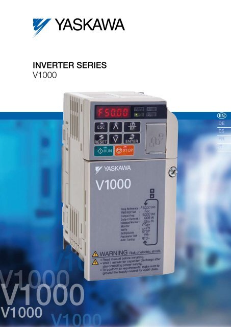
Inverter Series<br />
<strong>V1000</strong><br />
EN<br />
DE<br />
ES<br />
FR<br />
IT<br />
1000<br />
<strong>V1000</strong><br />
<strong>V1000</strong><br />
<strong>V1000</strong><br />
<strong>V1000</strong>
<strong>V1000</strong><br />
YASKAWA Inverter Drive Technology<br />
Contents<br />
Page 2<br />
Experience & Innovation<br />
A leader in Inverter Drives<br />
technology<br />
<strong>V1000</strong> – Easy and cost-saving<br />
handling through all kinds of<br />
applications<br />
Page 3<br />
”One for all“ –<br />
Multiple Applications<br />
Page 4/5<br />
Specifications<br />
Page 6<br />
Connection Diagram<br />
Content Page 7<br />
<strong>V1000</strong> Dimensions<br />
Experience & Innovation<br />
For more than 90 years YASKAWA has<br />
been manufacturing and supplying<br />
mechatronic products for machine<br />
building and industrial automation. Its<br />
standard products as well as tailor-made<br />
solutions are famous and have a high<br />
reputation for outstanding quality and<br />
durability.<br />
A leader in Inverter Drives<br />
technology<br />
Extensive research and development has<br />
allowed YASKAWA to remain at the forefront<br />
of motion control and automation technology.<br />
This technological leadership has helped<br />
to modernise industries such as mining,<br />
steel, pulp and paper, chemical, automotive,<br />
packaging, machine tool and semiconductor.<br />
focuses on all aspects of application,<br />
installation, operation and maintenance.<br />
Safety Integrated<br />
YASKAWA <strong>V1000</strong> is one of the first general<br />
purpose compact drives with built-in two<br />
channel hardware base block input. It already<br />
meets international safety standards and<br />
thereby supports machine builder to apply<br />
to international machine directives.<br />
Finless Type<br />
YASKAWA has as one of the first<br />
manufacturers promoted the development<br />
of finless type inverters for the European<br />
and international markets. Consequently the<br />
<strong>V1000</strong> is available as finless version for<br />
applications with an external cooling system.<br />
YASKAWA <strong>V1000</strong> Features<br />
Page 8<br />
<strong>V1000</strong> Finless Version<br />
Dimensions<br />
Page 9<br />
<strong>V1000</strong> IP66 Dimensions<br />
Page 10<br />
Options<br />
Page 11<br />
Ratings & Type Descriptions<br />
incl. finnless<br />
In 2007 YASKAWA produced its 10 millionth<br />
inverter in the new inverter plant in<br />
Yukuhashi, Japan. By this YASKAWA is<br />
probably the biggest inverter manufacturer in<br />
the world.<br />
The 10 millionth inverter was a <strong>V1000</strong>, the<br />
latest inverter developed by YASKAWA.<br />
Awarded by IEN magazine as being the<br />
‘most innovative product 2007’ at Hanover<br />
Fair Industry 2007 the <strong>V1000</strong> has raised the<br />
bar in the market in terms of usability and<br />
reliability.<br />
<strong>V1000</strong> – Easy and cost-saving<br />
handling through all kinds of<br />
applications<br />
This powerful little helper sets standards<br />
in terms of user friendliness and process<br />
orientation. The development of the <strong>V1000</strong><br />
Dual Safety Input, safety category 3<br />
(EN954-1) and stop category 0<br />
(EN60204-1) and IEC-61508 SIL2<br />
In normal duty (120% overload) one<br />
frame size larger motor can be driven<br />
Standard AC Motor and PM motor control<br />
V/f and open-loop current<br />
vector control<br />
One of the smallest inverter drives<br />
in the world<br />
Side-by-side mounting<br />
Icon-based programming<br />
Designed for 10 years of<br />
maintenance-free operation<br />
2 YASKAWA <strong>V1000</strong>
“One for all” – Multiple Applications<br />
YASKAWA <strong>V1000</strong> is a general purpose inverter drive covering the demands of a wide field of applications.<br />
Simple duties as well as requirements of complex systems need a higher level of functionality, reliability and easy handling,<br />
which are provided by the <strong>V1000</strong>.<br />
For energy saving, permanent magnet motor control is possible<br />
Selectable control method: open-loop current vector or V/f<br />
Small Design – Big Power: 150% overload in heavy duty service is possible. For applications with low overload<br />
requirements the drive can be operated with 120% overload in normal duty service. Consequently you can use a drive of<br />
smaller size to do the work of a bigger one.<br />
Worldwide specification CE, UL, cUL, RoHS (TÜV safety approved)<br />
High flux braking reduces braking time to the half<br />
Easy Installation<br />
Reliable Operation<br />
YASKAWA <strong>V1000</strong> reduces installation time and costs. Installable in tight<br />
spaces it requires a minimum of set-up time and provides you all the<br />
comfort of a modern up-to-date inverter drive.<br />
One of the smallest inverter drives in the world saves mounting<br />
space and cost by side-by-side mounting<br />
Application parameter pre-settings shorten set-up time<br />
Same handling and parameter structure for all YASKAWA inverters<br />
DriveWorksEZ visual programming tool. Simply drag and drop icons<br />
to customize your drive. Create special sequences and detection<br />
functions, then load them onto the drive.<br />
Quick Maintenance<br />
The <strong>V1000</strong> continues the tradition of YASKAWA by being the reliable<br />
link in your production chain.<br />
Designed for Long Performance Life (10 years 24 h per day at 80%<br />
nominal load.)<br />
Quick response on load and speed changes improves your<br />
machine performance<br />
Online Auto-Tuning to optimise for improved motor performance at<br />
low speed<br />
Optional external 24 VDC-supply assures communication and data<br />
flow in any power-down situation<br />
Dual safety input: safety category 3 (EN954-1), stop category 0 and<br />
IEC-61508 SIL2<br />
YASKAWA <strong>V1000</strong> is an inverter drive which adapts to user demands and provides<br />
maintenance functions that ensure quick replacement and minimize down time.<br />
Removable terminal board with parameter memory for quick and easy maintanance<br />
Screwless control terminal saves setup time<br />
3
Specifications<br />
Inverter output<br />
Inverter<br />
input<br />
Voltage class<br />
Single-phase 200 V<br />
Inverter model CIMR-VCBA* 1 0001 0002 0003 0006 0010 0012 00018* 6<br />
Motor output kW at normal duty* 2 0.18 0.37 0.75 1.1 2.2 3.0 –<br />
Motor output kW at heavy duty * 2 0.1 0.18 0.55 0.75 1.5 2.2 4.0<br />
Rated output current at normal duty [A]* 3 1.2 1.9 3.3 6 9.6 12 –<br />
Rated output current at heavy duty [A] 0.8* 4 1.6* 4 3.0* 4 5.0* 4 8.0* 5 11.0* 5 17.5* 5<br />
Overload<br />
125% for 60 sec normal duty, 150 % for 60 sec<br />
at heavy duty from inverter rated output current<br />
Rated output power at normal duty [kVA]* 0.5 0.7 1.3 2.3 3.7 4.6 -<br />
Rated output power at heavy duty [kVA]* 0.3 0.6 1.1 1.9 3.0 4.2 6.7<br />
Max. output voltage<br />
Three-phase 200 to 240 V (proportional to input voltage)<br />
Max. output frequency<br />
400 Hz<br />
Rated input voltage Single-phase 200 to 240 V, -15% to +10%<br />
Rated input frequency 50/60 Hz, ±5%<br />
* based on input voltage 220 V<br />
Inverter output<br />
Inverter<br />
input<br />
Voltage class<br />
Three-phase 200 V<br />
Inverter model CIMR-VC2A 0001 0002 0004 0006 0010 0012 0020 0030 0040 0056 0069<br />
Motor output kW at normal duty* 2 0.18 0.37 0.75 1.1 2.2 3.0 5.5 7.5 11.0 15.0 18.5<br />
Motor output kW at heavy duty* 2 0.1 0.2 0.4 0.75 1.5 2.2 4.0 5.5 7.5 11.0 15.0<br />
Rated output current at normal duty [A]* 3 1.2 1.9 3.5 6.0 9.6 12.0 19.6 30.0 40.0 56.0 69.0<br />
Rated output current at heavy duty [A] 0.8* 4 1.6* 4 3.0* 4 5.0* 4 8.0* 5 11.0* 5 17.5* 5 25.0* 5 33.0* 5 47.0* 5 60.0* 5<br />
Overload<br />
120% for 60 sec at normal duty, 150% for 60 sec at heavy duty from inverter rated output current<br />
Rated output power at normal duty [kVA]* 0.5 0.7 1.3 2.3 3.7 4.6 7.5 11.4 15.2 21.3 26.3<br />
Rated output power at heavy duty [kVA]* 0.3 0.6 1.1 1.9 3.0 4.2 6.7 9.5 12.6 17.9 22.9<br />
Max. output voltage<br />
Three-phase 200 to 240 V (proportional to input voltage)<br />
Max. output frequency<br />
400 Hz<br />
Rated input voltage Three-phase 200 to 240 V, -15% to +10%<br />
Rated input frequency 50/60 Hz, ±5%<br />
* based on input voltage 220V<br />
Voltage class<br />
Three-phase 400 V<br />
Inverter model CIMR-VC4A 0001 0002 0004 0005 0007 0009 0011 0018 0023 0031 0038<br />
Motor output kW at normal duty* 2 0.37 0.75 1.5 2.2 3.0 4.0 5.5 7.5 11 15.0 18.5<br />
Motor output kW at heavy duty* 2 0.18 0.37 0.75 1.5 2.2 3.0 4.0 5.5 7.5 11.0 15.0<br />
Rated output current at normal duty [A]* 3 1.2 2.1 4.1 5.4 6.9 8.8 11.1 17.5 23.0 31.0 38.0<br />
Rated output current at heavy duty [A]* 5 1.2 1.8 3.4 4.8 5.5 7.2 9.2 14.8 18.0 24.0 31.0<br />
Overload<br />
120% for 60 sec at normal duty, 150% for 60 sec at heavy duty from inverter rated output current<br />
Rated output power at normal duty [kVA]* 0.9 1.6 3.1 4.1 5.3 6.7 8.5 13.3 17.5 23.6 29.0<br />
Rated output power at heavy duty [kVA]* 0.9 1.4 2.6 3.7 4.2 5.5 7.0 11.3 13.7 18.3 23.6<br />
Max. output voltage<br />
Three-phase 380 to 480 V (proportional to input voltage)<br />
Max. output frequency<br />
400 Hz<br />
Inverter Rated input voltage Three-phase 380 to 480 V, -15% to +10%<br />
input Rated input frequency 50/60 Hz, ±5%<br />
* based on input voltage 400 V<br />
Inverter output<br />
* 1 Drives with a single-phase power supply input have three-phase output. Single-phase motors cannot be used.<br />
* 2 The motor capacity (kW) refers to a YASKAWA 4-pole, 60 Hz, 200 V motor. The rated output current of the drive output amps should be equal to or greater than the motor rated current.<br />
* 3 at 2 kHz carrier frequency without derating<br />
* 4 at 10 kHz carrier frequency without derating<br />
* 5 at 8 kHz carrier frequency without derating<br />
* 6 only heavy duty available<br />
4 YASKAWA <strong>V1000</strong>
Rotational Auto-Tuning must be performed to achieve the performance described with Open Loop Vector Control.<br />
Control Functions<br />
Protection Function<br />
Operating Environment<br />
Control methods<br />
Frequency Control Range<br />
Frequency Accuracy<br />
(Temperature Fluctuation)<br />
Frequency Setting<br />
Resolution<br />
Output Frequency<br />
Resolution<br />
Frequency Setting<br />
Resolution<br />
Starting Torque<br />
Specifications<br />
Open Loop Vector Control (Current Vector), V/f Control, PM Open Loop Vector Control (for SPM and IPM motors)<br />
0.01 to 400 Hz<br />
Digital input: within ±0.01% of the max. output frequency (-10°C to +50°C))<br />
Analog input: within ±0.1% of the max. output frequency (25°C ±10°C)<br />
Digital input: 0.01 Hz<br />
Analog input: 1/1000 of max. frequency<br />
20 bit of maximum output frequency (parameter E1-04 setting)<br />
Main frequency reference: 0..10 V (20 kΩ) 10 bit, 4..20 mA (250 Ω) or 0..20 mA (250 Ω) 9-bit<br />
Main speed reference : Pulse Train Input (max. 32 kHz)<br />
200% / 0.5 Hz (assumes Heavy Duty rating AC Motor of 3.7 kW or less using Open Loop Vector Control),<br />
50% / 6 Hz (assumes PM Open Loop Vector Control)<br />
1:100 (Open Loop Vector Control), 1:20 to 40 (V/f Control), 1:10 (PM Open Loop Vector Control)<br />
Speed Control Range<br />
Speed Control Accuracy ±0.2% in Open Loop Vector Control (25°C ±10°C) * 1<br />
Speed Response<br />
5 Hz in Open Loop Vector (25°C ±10°C) (requires Rotational Auto-Tuning)<br />
Torque Limit<br />
Open Loop Vector Control allows separate settings in four quadrants<br />
Accel/Decel Time<br />
0.0 to 6000.0 s (4 selectable combinations of independent acceleration and deceleration settings)<br />
Braking Torque<br />
V/f Characteristics<br />
Main Control<br />
Functions<br />
q Short-time decel torque* 2 : over 150% for 0.1/0.2 kW motors, over 100% for 0.4/ 0.75 kW motors, over 50% for 1.5 kW motors, and over 20% for<br />
2.2 kW and above motors (overexcitation braking/High-Slip Braking: approx. 40%)<br />
w Continuous regen. torque: approx. 20% (approx. 125% with dynamic braking resistor option* 3 : 10% ED, 10 s, internal braking transistor)<br />
User-selected programs, V/f preset patterns possible<br />
Momentary power loss ride-thru, Speed search, Overtorque detection, Torque limit, 17-step speed (max), Accel/decel time switch, S-curve accel/decel,<br />
3-wire sequence, Auto-tuning (rotational, stationary tuning for resistance between lines), Dwell, Cooling fan on/off switch, Slip compensation, Torque<br />
compensation, Frequency jump, Upper/lower limits for frequency reference, DC injection braking at start and stop, Overexcitation braking, High slip<br />
braking, PID control (with sleep function), Energy saving control, MEMOBUS comm. (RS-485/422 max, 115.2 kbps), Fault restart, Application presets,<br />
DriveWorksEZ (customized function), Removable terminal block with parameter backup function...<br />
Motor overheat protection based on output current<br />
Drive stops when output current exceeds 200% of Heavy Duty Rating<br />
Motor Protection<br />
Momentary Overcurrent Protection<br />
Overload Protection Drive stops after 60 s at 150% of rated output current (Heavy Duty Rating)* 4<br />
Overvoltage Protection<br />
200 V class: Stops when DC bus exceeds approx. 410 V<br />
400 V class: Stops when DC bus exceeds approx. 820 V<br />
Stops when DC bus voltage falls below the following levels:<br />
Undervoltage Protection<br />
Three-phase 200 V class: approx. 190 V, single-phase 200 V class: approx. 160 V, three-phase 400 V class: approx. 380 V, three-phase 380 V class:<br />
approx. 350 V<br />
Momentary Power Loss Ride-Thru Stops after approx. 15 ms (default). Parameter settings allow the drive to continue running if power loss lasts for up to approx. 2 s * 5<br />
Heatsink Overheat Protection Protection by thermistor<br />
Braking Resistance Overheat<br />
Protection<br />
Overheat sensor for braking resistor (optional ERF-type, 3% ED)<br />
Stall Prevention<br />
Separate settings allowed during acceleration, and during run. Enable/disable only during deceleration.<br />
Ground Fault Protection Protection by electronic circuit * 6<br />
Charge LED<br />
Charge LED remains lit until DC bus has fallen below approx. 50 V<br />
Area of Use<br />
Indoors<br />
Ambient Temperature -10°C to +50°C (open chassis), -10°C to +40°C (NEMA Type 1)<br />
Humidity<br />
95 RH% or less (no condensation)<br />
Storage Temperature<br />
-20°C to +60°C (short-term temperature during transportation)<br />
Altitude Max. 1000 m (output derating of 1% per 100 m above 1000 m, max. 3000 m)<br />
Shock<br />
10 to less than 20 Hz (9.8 m/s2) max., 20 to 55 Hz (5.9 m/s2) max.<br />
Safety Standard<br />
UL508C, EN954-1 Cat. 3, IEC/EN61508 SIL2<br />
Protection Design<br />
IP20 open-chassis, NEMA Type 1 enclosure<br />
* 1 Speed control accuracy may vary slightly depending on installation conditions or motor used.<br />
* 2 Momentary average deceleration torque refers to the deceleration torque from 60Hz down to 0 Hz. This may vary depending on the motor.<br />
* 3 If L3-04 is enabled when using a braking resistor or braking resistor unit, the motor may not stop within the specifi ed deceleration time.<br />
* 4 Overload protection may be triggered at lower levels if output frequency is below 6 Hz.<br />
* 5 Varies by drive capacity. Drives smaller than 7.5 kW (CIMR-VA2A0004/CIMR-VA4A0023) require a separate Momentary Power Loss Recovery Unit to continue operating during a momentary power loss of 2 s.<br />
* 6 Protection may not be provided under the following conditions as the motor windings are grounded internally during run:<br />
• Low resistance to ground from the motor cable or terminal block.<br />
• Drive already has a short-circuit when the power is turned on.<br />
5
Connection Diagram<br />
DC reactor<br />
(option)<br />
Link<br />
Thermal<br />
relay<br />
Braking resistor<br />
(option)<br />
Fuses<br />
Power<br />
Supply<br />
Filter<br />
Main<br />
Switch<br />
Forward / Stop<br />
Reverse / Stop<br />
External fault<br />
Ground<br />
Shielded<br />
Cable<br />
Fault reset<br />
Multi-speed step 1<br />
Multi-speed step 2<br />
Multi-function<br />
digital inputs (default<br />
setting)<br />
Multi-function pulse / analog inputs<br />
(default: frequency reference)<br />
DIP<br />
switch S3<br />
Shield ground<br />
terminal<br />
SINK<br />
SOURCE<br />
t<br />
Pulse Input<br />
(max. 32 kHz)<br />
Analog input power supply<br />
+10.5 max. 20 mA<br />
Multi-function analog input 1<br />
0 to +10 V (20 kΩ)<br />
Multi-function analog input 2<br />
0 to +10 V (20 kΩ)<br />
0/4 to 20 m A (250 Ω)<br />
Terminal resistance<br />
(120 Ω, 1/2 W)<br />
Fault<br />
During run<br />
Frequency agree<br />
Photocoupler<br />
output common<br />
Pulse train output<br />
(max. 32 kHz)<br />
(Output frequency)<br />
Multi-function relay output<br />
250 VAC / 30 VDC (10 mA to 1 A)<br />
(default setting)<br />
Analog output<br />
0 to +10 VDC (2 mA)<br />
(Output frequency)<br />
Multi-function photocouplee<br />
output<br />
48 Vdc, 2 to 50 mA<br />
(default setting)<br />
Monitor outputs<br />
(default setting)<br />
Safe Disable<br />
inputs<br />
MEMOBUS comm.<br />
RS-485/422<br />
max. 115 kBps<br />
Use twisted pair cables.<br />
Use shielded twisted pair cables.<br />
Indicates a main circuit terminal.<br />
Indicates a control circuit terminal.<br />
6 YASKAWA <strong>V1000</strong>
IP20/Open-Chassis (without an EMC filter)<br />
<strong>V1000</strong> Dimensions<br />
Voltage Class<br />
Single-Phase<br />
200 V Class<br />
Three-Phase<br />
200 V Class<br />
Drive Model<br />
Dimensions in mm<br />
CIMR-VC W1 H1 W H D t1 H2 D1 Weight (kg)<br />
BA0001B<br />
76 3<br />
6.5 0.6<br />
BA0002B 56 118 68 128<br />
5<br />
BA0003B 118 5 38.5 1.0<br />
2A0001B<br />
76 3<br />
6.5 0.6<br />
2A0002B<br />
56 118 68 128<br />
5<br />
2A0004B 108<br />
38.5 0.9<br />
5<br />
2A0006B 128 58.5 1.1<br />
*inner<br />
diameter<br />
for M4<br />
screws<br />
Voltage Class<br />
Single-Phase<br />
200 V Class<br />
Three-Phase<br />
200 V Class<br />
Three-Phase<br />
400 V Class<br />
Drive Model<br />
Dimensions in mm<br />
CIMR-VC W1 H1 W H D t1 H2 D1 Weight (kg)<br />
BA0006B<br />
137.5<br />
1.7<br />
96<br />
108<br />
58<br />
BA0010B 154 5 5<br />
1.8<br />
118<br />
128<br />
BA0012B 128 140 163<br />
2.4<br />
65<br />
BA0018B 158 170 180 3.0<br />
2A0010B<br />
129<br />
96<br />
108<br />
2A0012B 118<br />
128 137.5 5 5<br />
58 1.7<br />
2A0020B 128 140 143 65 2.4<br />
4A0001B<br />
81<br />
10 1.0<br />
4A0002B 99 28 1.2<br />
4A0004B 137.5<br />
96<br />
108<br />
4A0005B<br />
118<br />
128<br />
5 5<br />
58 1.7<br />
4A0007B<br />
154<br />
4A0009B<br />
4A0011B 128 140 143 65 2.4<br />
*inner diameter for M4 screws<br />
IP20/NEMA Type 1 (without an EMC filter)<br />
Voltage Class<br />
Single-Phase<br />
200 V Class<br />
Three-Phase<br />
200 V Class<br />
Drive Model<br />
Dimensions in mm<br />
CIMR-VC W1 H2 W H1 D t1 H5 D1 H H4 H3 H6 Weight (kg)<br />
BA0001F<br />
76 3 6.5 0.8<br />
BA0002F 56 118 68 128<br />
5 149.5 20 4 1.5<br />
BA0003F 118 5 39 1.2<br />
2A0001F<br />
76 3 6.5<br />
0.8<br />
2A0002F<br />
56 118 68 128<br />
5 149.5 20 4 1.5<br />
2A0004F 108<br />
39 1.1<br />
5<br />
2A0006F 128 59 1.3<br />
*inner<br />
diameter<br />
for M4<br />
screws<br />
Voltage Class<br />
Single-Phase<br />
200 V Class<br />
Three-Phase<br />
200 V Class<br />
Three-Phase<br />
400 V Class<br />
Drive Model<br />
Dimensions in mm<br />
CIMR-VC W1 H2 W H1 D t1 H5 D1 H H4 H3 H6 Weight (kg)<br />
BA0006F<br />
137.5<br />
1.9<br />
96 108<br />
58 149.5 4 1.5<br />
BA0010F 154 20 2.0<br />
118 128 5 5<br />
BA0012F 128 140 163<br />
153<br />
2.6<br />
65<br />
4.8 5<br />
BA0018F 158 170 180 171 38 3.3<br />
2A0010F<br />
96<br />
118 108 129<br />
58 149.5<br />
2A0012F 128 137.5 5 5<br />
20<br />
4 1.5 1.9<br />
2A0020F 128 140 143 65 153 4.8 5 2.6<br />
4A0001F<br />
81<br />
10<br />
1.2<br />
4A0002F 99 28 1.4<br />
4A0004F<br />
96<br />
118 108 137.5<br />
149.5 4 1.5<br />
4A0005F<br />
128 5 5<br />
20<br />
58 1.9<br />
4A0007F<br />
154<br />
4A0009F<br />
4A0011F 128 140 143 65 153 4.8 5 2.6<br />
*inner diameter for M4 screws<br />
Voltage Class<br />
Three-Phase<br />
200 V Class<br />
Three-Phase<br />
400 V Class<br />
Drive Model<br />
Dimensions in mm<br />
CIMR-VC W1 H2 W H1 D t1 H5 D1 H H4 H3 H6 d Weight (kg)<br />
2A0030F<br />
122 248 140 234 140<br />
55 254 13<br />
13<br />
6<br />
5<br />
1.5 M5 3.8<br />
2A0040F<br />
2A0056F 160 284 180 270 163 75 290 15 5.5<br />
2A0069F 192 336 220 320 187 22 78 350 15 7 M6 9.2<br />
4A0018F<br />
122 248 140 234 140<br />
55 254 13 3.8<br />
4A0023F<br />
5 13<br />
6 1.5 M5<br />
4A0031F<br />
160 284 180 270 143 15 5.2<br />
290<br />
4A0038F 163 75 13 5.5<br />
*inner<br />
diameter<br />
for M5/M6<br />
screws<br />
7
<strong>V1000</strong> Finless Version Dimensions<br />
… for Models BA0001~2A0006<br />
Voltage Class<br />
Single-Phase<br />
200 V Class<br />
Three-Phase<br />
200 V Class<br />
Drive Model<br />
CIMR-VC<br />
Dimensions in mm<br />
W H D W1 H1 H2 t1 Weight (kg)<br />
BA0001<br />
71<br />
0.6<br />
BA0002 68 128<br />
56 118 5 3<br />
BA0003 81 0.8<br />
2A0001<br />
0.6<br />
2A0002<br />
68 128 71 56 118 5 3<br />
2A0004<br />
0.7<br />
2A0006<br />
*inner<br />
diameter<br />
for M4<br />
screws<br />
… for Models BA0006~4A0009<br />
Voltage Class<br />
Single-Phase<br />
200 V Class<br />
Three-Phase<br />
200 V Class<br />
Three-Phase<br />
400 V class<br />
Drive Model<br />
CIMR-VC<br />
Dimensions in mm<br />
W H D W1 H1 H2 t1 Weight (kg)<br />
108 128<br />
79.5<br />
96 118 5 4 1.1<br />
BA0006<br />
BA0010 91<br />
2A0008<br />
2A0010 108 128<br />
71<br />
2A0012 79.5<br />
4A0001<br />
4A0002<br />
71<br />
4A0004 79.5<br />
108 128<br />
4A0005<br />
4A0007<br />
96<br />
4A0009<br />
96 118 5 4 1.0<br />
96 118 5 4<br />
0.9<br />
1.0<br />
1.1<br />
*inner<br />
diameter<br />
for M4<br />
screws<br />
… for Models BA0012~4A0011<br />
Voltage Class<br />
Single-Phase<br />
200 V Class<br />
Three-Phase<br />
200 V Class<br />
Three-Phase<br />
400 V class<br />
Drive Model<br />
CIMR-VC<br />
Dimensions in mm<br />
W H D W1 H1 H2 t1 Weight (kg)<br />
BA0012 140 128 98 128 118 5 4 1.4<br />
2A0018<br />
2A0020<br />
140 128 78 128 118 5 4 1.3<br />
4A0011 140 128 78 128 118 5 4 1.3<br />
*inner<br />
diameter<br />
for M4<br />
screws<br />
… for Models 2A0030~4A0038<br />
Voltage Class<br />
Three-Phase<br />
200 V Class<br />
Three-Phase<br />
400 V Class<br />
Drive Model<br />
CIMR-VC<br />
Dimensions in mm<br />
W H D W1 H1 H2 H3 H4 H5 d t1 Weight (kg)<br />
2A0030<br />
140 260 145 122 248 6 234 13<br />
3.2<br />
2A0040<br />
M5<br />
5 5<br />
2A0056 180 300 147 160 284 8 270<br />
4.6<br />
15<br />
2A0069 220 350 152 192 336 7 320 M6 7.0<br />
4A0018<br />
3.1<br />
140 260 145 122 248 6 234 13<br />
4A0023 3.2<br />
5 M5 5<br />
4A0031<br />
4.3<br />
180 300 147 160 284 8 270 15<br />
4A0038 4.6<br />
*inner<br />
diameter<br />
for M5/M6<br />
screws<br />
8 YASKAWA <strong>V1000</strong>
<strong>V1000</strong> IP66 Dimensions<br />
Ø6.5<br />
V 1000<br />
IP 66<br />
H<br />
H1<br />
.<br />
H2<br />
W1<br />
D<br />
t1<br />
W<br />
Inverter model<br />
CIMR-VC<br />
BA0001<br />
BA0002<br />
BA0003<br />
BA0006<br />
BA0010<br />
BA0012<br />
BA0018<br />
2A0001<br />
2A0002<br />
2A0004<br />
2A0006<br />
2A0010<br />
2A0012<br />
2A0020<br />
2A0030<br />
2A0040<br />
2A0056<br />
2A0069<br />
4A0001<br />
4A0002<br />
4A0004<br />
4A0005<br />
4A0007<br />
4A0009<br />
4A0011<br />
4A0018<br />
4A0023<br />
4A0031<br />
4A0038<br />
Dimensions in mm<br />
W H D W1 H1 H2 t1<br />
262 340 173.5 214 321 9 2<br />
under development<br />
262 340 173.5 214 321 9 2<br />
under development<br />
262 340 173.5 214 321 9 2<br />
under development<br />
Data and Dimensions are preliminary and subject to be changed at any time.<br />
9
Options<br />
Name Purpose Model, Manufacturer<br />
1-phase 200 V Filter:<br />
CIMR-VCBA0001 FS23638-10-07<br />
CIMR-VCBA0002 FS23638-10-07<br />
CIMR-VCBA0003 FS23638-10-07<br />
CIMR-VCBA0006 FS23638-20-07<br />
CIMR-VCBA0010 FS23638-20-07<br />
CIMR-VCBA0012 FS23638-30-07<br />
CIMR-VCBA0018 FS23638-40-07<br />
3-phase 200 V Filter:<br />
CIMR-VC2A0001 FS23637-8-07<br />
CIMR-VC2A0002 FS23637-8-07<br />
CIMR-VC2A0004 FS23637-8-07<br />
CIMR-VC2A0006 FS23637-8-07<br />
CIMR-VC2A0010 FS23637-14-07<br />
CIMR-VC2A0012 FS23637-14-07<br />
Input noise filter<br />
Reduces noise from the line that enters into the drive input power system.<br />
CIMR-VC2A0020 FS23637-24-07<br />
Should be installed as close as possible to the drive.<br />
CIMR-VC2A0030 FS23637-52-07<br />
CIMR-VC2A0040 FS23637-52-07<br />
CIMR-VC2A0056 FS23637-68-07<br />
CIMR-VC2A0069 FS23637-80-07<br />
3-phase 400 V Filter:<br />
CIMR-VC4A0001 FS23639-5-07<br />
CIMR-VC4A0002 FS23639-5-07<br />
CIMR-VC4A0004 FS23639-5-07<br />
CIMR-VC4A0005 FS23639-10-07<br />
CIMR-VC4A0007 FS23639-10-07<br />
CIMR-VC4A0009 FS23639-10-07<br />
CIMR-VC4A0011 FS23639-15-07<br />
CIMR-VC4A0018 FS23639-30-07<br />
CIMR-VC4A0023 FS23639-30-07<br />
CIMR-VC4A0031 FS23639-50-07<br />
CIMR-VC4A0038 FS23639-50-07<br />
Braking resistor Used to shorten the deceleration time by dissipating regenerative energy through a resistor (3% ED). ERF-150WJ series<br />
24 V power supply<br />
USB copy unit<br />
(RJ-45/USB compatible plug)<br />
Support tools (DriveWizard Plus)<br />
cable<br />
LCD operator<br />
LCD operator extension cable<br />
Communication<br />
interface<br />
unit<br />
MECHATROLINK-2<br />
CC−link<br />
DeviceNet<br />
PROFIBUS−DP<br />
CANopen<br />
Provides power supply for the control circuit and option boards. Note: Parameter settings cannot be<br />
changed when the drive is operating solely from this power supply.<br />
Adapter for connecting the drive to the USB port of a PC. (e.g. for Support Tool Drive Wizard Plus)<br />
Can copy parameter settings to be later transferred to another drive.<br />
Connects the drive to a PC for use with DriveWizard.<br />
For easier operation when using the optional LCD operator. Allows for remote operation. Includes a<br />
Copy function for saving drive settings.<br />
Cable for connecting the LCD operator.<br />
Allows control of the drive via a fieldbus network.<br />
Momentary power loss recovery unit Ensures continued drive operation for a power loss of up to 2 s.<br />
Attachment for external heatsink<br />
Mechanical kit to install the drive with the heatsink out of the cabinet.<br />
Note: current derating must be considered when this installation method is used.<br />
PS-V10S<br />
PS-V10M<br />
JVOP-181<br />
WV103<br />
JVOP-180<br />
WV001: 1 m<br />
WV003: 3 m<br />
SI-T3/V<br />
SI-C3/V<br />
SI-N3/V<br />
SI-P3/V<br />
SI-S3/V<br />
P0010 type (200 V class)<br />
P0020 type (400 V class)<br />
(Please contact your YASKAWA<br />
representative)<br />
Screw-type terminal board Control terminal board with screw-type terminals. Available soon<br />
For the use with holes through the panel. 100-039-992<br />
Plus operator mounting kit<br />
For the use with panel mounted threaded studs. 100-039-993<br />
Note: contact the manufacturer in question for availability and specifications of non-YASKAWA products.<br />
10 YASKAWA <strong>V1000</strong>
Ratings & Type Descriptions<br />
CIMR- V C B A 0001 B A A<br />
Inverter Series<br />
Revision<br />
<strong>V1000</strong> V 1st A<br />
Specification<br />
Coating Specification and Protection<br />
Japanese spec. A Standard A<br />
Chinese spec. B Moisture (humidity)/Dust-proof M<br />
European spec. C Oil-proof N<br />
USA spec. U Salt-proof C<br />
Asia spec. T Vibration-proof S<br />
Gas-proof<br />
K<br />
Moisture/Dust and vibration-proof<br />
P<br />
Input Voltage Oil and vibration-proof Q<br />
Single-phase 200 VAC B Gas-proof + vibration-proof B<br />
Three-phase 200 VAC 2 Oil-proof double coating D<br />
Three-phase 400 VAC 4 Moisture double coating E<br />
Customer Specification<br />
Enclosure<br />
Standard A Fin Filter Protection level<br />
Standard No IP00 A<br />
Standard No IP20 without top cover B<br />
Standard No IP20 with top cover C<br />
Standard No NEMA 1 (IP20) F<br />
Built in IP66 H<br />
No No Finless (IP20) J<br />
Single-phase 200 VAC<br />
Normal duty<br />
Heavy duty<br />
Rated output current Max. applicable motor Rated output current Max. applicable motor<br />
0001 1.2 A 0.18 kW 0.8 A 0.1 kW<br />
0002 1.9 A 0.37 kW 1.6 A 0.18 kW<br />
0003 3.3 A 0.75 kW 3.0 A 0.55 kW<br />
0006 6.0 A 1.1 kW 5.0 A 0.75 kW<br />
0010 9.6 A 2.2 kW 8.0 A 1.5 kW<br />
0012 12.0 A 3.0 kW 11.0 A 2.2 kW<br />
0018 – – 17.5 A 4.0 kW<br />
Three-phase 200 VAC<br />
Normal duty<br />
Heavy duty<br />
Rated output current Max. applicable motor Rated output current Max. applicable motor<br />
0001 1.2 A 0.4 kW 0.8 A 0.1 kW<br />
0002 1.9 A 0.37 kW 1.6 A 0.2 kW<br />
0004 3.5 A 0.75 kW 3.0 A 0.4 kW<br />
0006 6.0 A 1.1 kW 5.0 A 0.75 kW<br />
0010 9.6 A 2.2 kW 8.0 A 1.5 kW<br />
0012 12.0 A 3.0 kW 11.0 A 2.2 kW<br />
0020 19.6 A 5.5 kW 17.5 A 4.0 kW<br />
0030 30.0 A 7.5 kW 25.0 A 5.5 kW<br />
0040 40.0 A 11.0 kW 33.0 A 7.5 kW<br />
0056 56.0 A 15.0 kW 47.0 A 11.0 kW<br />
0069 69.0 A 18.5 kW 60.0 A 15.0 kW<br />
Three-phase 400 VAC<br />
Normal duty<br />
Heavy duty<br />
Rated output current Max. applicable motor Rated output current Max. applicable motor<br />
0001 1.2 A 0.37 kW 1.2 A 0.2 kW<br />
0002 2.1 A 0.75 kW 1.8 A 0.4 kW<br />
0004 4.1 A 1.5 kW 3.4 A 0.75 kW<br />
0005 5.4 A 2.2 kW 4.8 A 1.5 kW<br />
0007 6.9 A 3.0 kW 5.5 A 2.2 kW<br />
0009 8.8 A 4.0 kW 7.2 A 3.0 kW<br />
0011 11.1 A 5.5 kW 9.2 A 4.0 kW<br />
0018 17.5 A 7.5 kW 14.8 A 5.5 kW<br />
0023 23.0 A 11.0 kW 18.0 A 7.5 kW<br />
0031 31.0 A 15.0 kW 24.0 A 11.0 kW<br />
0038 38.0 A 18.5 kW 31.0 A 15.0 kW<br />
11
V<br />
YASKAWA Electric Europe GmbH<br />
Hauptstr. 185<br />
65760 Eschborn<br />
Deutschland / Germany<br />
+49 6196 569-300<br />
info@yaskawa.de<br />
www.yaskawa.eu.com<br />
Specifications are subject to change without notice<br />
for ongoing product modifications and improvements.<br />
© YASKAWA Electric Europe GmbH. All rights reserved.<br />
Literature No. YEG_INV_<strong>V1000</strong>_EN_v3_1109<br />
Printed in Germany November 2009