Ontech GSM Mini 9009 Ontech GSM Relay 9010 - Ondico
Ontech GSM Mini 9009 Ontech GSM Relay 9010 - Ondico
Ontech GSM Mini 9009 Ontech GSM Relay 9010 - Ondico

You also want an ePaper? Increase the reach of your titles
YUMPU automatically turns print PDFs into web optimized ePapers that Google loves.
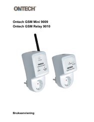
<strong>Ontech</strong> <strong>GSM</strong> <strong>Mini</strong> <strong>9009</strong><br />
<strong>Ontech</strong> <strong>GSM</strong> <strong>Relay</strong> <strong>9010</strong><br />
User Manual
Welcome<br />
Thank you for choosing <strong>Ontech</strong> <strong>GSM</strong> <strong>Mini</strong> <strong>9009</strong>.<br />
We hope that the product will satisfy your needs and that you will find this manual<br />
easy to handle and that it guides you in an appropriate way.<br />
If you want to learn more, please visit our web site at www.ondico.se, where you<br />
can find more information.<br />
Questions can be directed to support@ondico.se.<br />
In this manual the <strong>Ontech</strong> <strong>GSM</strong> <strong>Mini</strong> <strong>9009</strong> will sometimes be called master unit and<br />
<strong>Ontech</strong> <strong>GSM</strong> <strong>Relay</strong> <strong>9010</strong> will be called slave unit.<br />
SMS text will be shown with gray background and and bold text, for example:<br />
1234#1*0#<br />
Also the buttons to be pressed when using a telephone in tone mode (not pulse) is<br />
shown in this way.<br />
Text in italic indicates a menu in your mobile phone, for example;<br />
Contacts<br />
Important!<br />
Not intended for direct plug-in equipment, only for plugs with a cord.<br />
-2-
Content<br />
Welcome .......................................................................................................................... 2<br />
<strong>Ontech</strong> <strong>GSM</strong> <strong>Mini</strong> <strong>9009</strong> ................................................................................................. 5<br />
Overview.................................................................................................................................................................5<br />
Content in package .........................................................................................................................................6<br />
Get started.............................................................................................................................................................6<br />
Remote relay........................................................................................................................................................ 8<br />
Operate the relay manually................................................................................................................... 8<br />
Operate the relay by calling it up......................................................................................................8<br />
Operate the relay with SMS .................................................................................................................. 9<br />
Alarm...................................................................................................................................................................... 10<br />
Connect an alarm detector................................................................................................................ 10<br />
Change operation mode between NO and NC.................................................................... 10<br />
Alarmrelay..................................................................................................................................................... 12<br />
Turn on/off the alarm function........................................................................................................ 12<br />
Turn off the alarm function by calling up ................................................................................. 12<br />
Turn off the alarm function with SMS.......................................................................................... 12<br />
When an alarm is activated................................................................................................................ 13<br />
Interpreting the SMS .............................................................................................................................. 13<br />
Acknowledge an alarm......................................................................................................................... 13<br />
Temperature guard....................................................................................................................................... 14<br />
Temperature...................................................................................................................................................... 14<br />
Status-SMS.......................................................................................................................................................... 15<br />
Power the unit with battery .................................................................................................................... 16<br />
Functions............................................................................................................................................................. 16<br />
Commands................................................................................................................................................... 16<br />
Push button ................................................................................................................................................. 17<br />
The lamps of the unit............................................................................................................................. 17<br />
<strong>Ontech</strong> <strong>GSM</strong> <strong>Relay</strong> <strong>9010</strong> .............................................................................................19<br />
Overview.............................................................................................................................................................. 19<br />
Content of the package............................................................................................................................. 19<br />
Get started.......................................................................................................................................................... 20<br />
The identity of the unit ......................................................................................................................... 20<br />
Setting the radio channel.................................................................................................................... 21<br />
Remote relay..................................................................................................................................................... 23<br />
Operate the relay manually................................................................................................................ 23<br />
Operate the relay by calling it up................................................................................................... 23<br />
Operate the relay with SMS ............................................................................................................... 24<br />
Alarm function................................................................................................................................................. 25<br />
-3-
Connect an alarm detector................................................................................................................ 25<br />
Change operation mode between NO and NC.................................................................... 25<br />
Turn on/off the alarm function........................................................................................................ 27<br />
When an alarm is activated................................................................................................................ 27<br />
Acknowledge an alarm......................................................................................................................... 27<br />
Functions............................................................................................................................................................. 29<br />
Push button ................................................................................................................................................. 29<br />
The lamp of the unit............................................................................................................................... 29<br />
Trubble shooting............................................................................................................................................ 30<br />
Tip!........................................................................................................................................................................... 31<br />
<strong>Ontech</strong> <strong>GSM</strong> <strong>Mini</strong> <strong>9009</strong>......................................................................................................................... 32<br />
<strong>Ontech</strong> <strong>GSM</strong> <strong>Relay</strong> <strong>9010</strong>....................................................................................................................... 32<br />
Declaration of comformity....................................................................................................................... 33<br />
-4-
<strong>Ontech</strong> <strong>GSM</strong> <strong>Mini</strong> <strong>9009</strong><br />
Overview<br />
<strong>Ontech</strong> <strong>GSM</strong> <strong>Mini</strong> <strong>9009</strong> has a built-in power relay 230V/16A which can be operated<br />
with SMS or by an ordinary telephone call. The unit also has two alarm inputs which<br />
both can be set to operate in either Normally Open-mode or Normally Closed-mode.<br />
When the alarm input is activated an SMS will be sent to up to ten different mobile<br />
phone numbers.<br />
The unit has a temperature guard that sends an alarm message if the temperature<br />
drops below 5 degrees Celsius. The unit also reports the actual temperature.<br />
<strong>Ontech</strong> <strong>GSM</strong> <strong>Relay</strong> <strong>9010</strong> is a slave unit that communicates with <strong>Ontech</strong> <strong>GSM</strong> <strong>Mini</strong><br />
<strong>9009</strong> with a short range radio. The unit has a built-in power relay 230V/16A and two<br />
alarm inputs. Up to seven <strong>Ontech</strong> <strong>GSM</strong> <strong>Relay</strong> <strong>9010</strong> can be connected and<br />
individually operated by each <strong>Ontech</strong> <strong>GSM</strong> <strong>Mini</strong> <strong>9009</strong> . The operating range is<br />
approx. 30 meters, but each slave unit also works as a repeater in order to increase<br />
the operating range.<br />
-5-
Content in package<br />
• <strong>Ontech</strong> <strong>GSM</strong> <strong>Mini</strong> <strong>9009</strong><br />
• Antenna<br />
• Users Manual<br />
• Connection cable<br />
Get started<br />
In order to use the unit you must have an SIM-card for a mobile telephone and<br />
access to a mobile phone.<br />
1. Insert the SIM-card in a <strong>GSM</strong> mobile phone.<br />
2. Deactivate the PIN-code function. See the user manual of the mobile<br />
phone..<br />
3. Choose Contacts in the mobile phones menu.<br />
Be sure you are saving the settings in the memory of the SIM-card<br />
and not in the memory of the telephone.<br />
a. Create a new entry, name it ”PINCODE”<br />
b. In the field for telephone number, enter your personal four digit<br />
number. This number is the PINCODE you must enter each time<br />
you contact the unit..<br />
4. Create a send list for alarm<br />
a. Create a new contact. Name it ”SMS0” (note that 0 is zero and not<br />
the letter O).<br />
b. Enter the mobile phone number for the receiver of the SMS. Save.<br />
c. The following records in the send-list is named SMS1, SMS2 etc,<br />
and the mobile numbers are entered. All numbers from SMS0 to<br />
SMS9 can be used.<br />
5. If you wish to activate the temperature guard (see page 14.)<br />
a. Create a new contact. Name it ”TEMP”. No phone number has to<br />
be entered but if the phone requires it, any number can be<br />
entered.<br />
6. If you wish to activate ALARMRELAY (see page 12.)<br />
-6-
a. Create a new contact. Name it ”ALARMRELAY”. No phone number<br />
has to be entered but if the phone requires it, any number can be<br />
entered.<br />
7. Turn off the mobile phone and remove the SIM-card.<br />
8. Remove the cover door on back of the unit. Use a small screwdriver.<br />
9. Insert the SIM-card in the holder (see below). Replace the cover door.<br />
10. Connect the antenna to the unit<br />
11. Insert the unit in a power jack. The following happens:<br />
a. The green lamp starts flashing for about 45 seconds. This<br />
indicates that the unit is searching an <strong>GSM</strong> network.<br />
b. Finally the green lamp is lit. The unit is communicating with the<br />
<strong>GSM</strong> network and the unit is ready for use.<br />
c. If both the red and the green lamp is flashing, this indicates:<br />
i. SIM-kort is missing<br />
ii. The PIN-code on the SIM-card is not deactivated. See<br />
item 2.<br />
-7-
Remote relay<br />
With this function you can call up or send SMS to the unit and operate the<br />
230V/16A relay.<br />
Insert the unit in the wall power socket you wish. Put the power contact of the<br />
device you want to operate in the power socket of the unit.<br />
Operate the relay manually<br />
You can make the relay switch by pressing the button on the unit. When the relay is<br />
on, the red lamp is lit and when the relay is off, the red lamp is not lit.<br />
Operate the relay by calling it up<br />
1. Call up the unit. Be sure you use tone mode on the telephone.<br />
2. The unit answers with a beep.<br />
3. Press your PIN-code and then #.<br />
Example: 1234#<br />
If the PIN-code is correct the unit replies with a beep. If it is not correct the<br />
call is disconnected. Call again and try.<br />
4. Turn on the relay by pressing the following buttons:<br />
1*1#<br />
The unit replies with a beep. Hang up the receiver. If the unit replies with<br />
two beeps, try again.<br />
5. Turn off the relay by pressing the following buttons:<br />
0*1#<br />
The unit replies with a beep. Hang up the receiver. If the unit replies with<br />
two beeps, try again.<br />
6. Turn on the relay with timer function<br />
The relay can be turned on and you can set the number of hours you want<br />
it to be active before it switches off (between 1 and 99 h). Press the<br />
following buttons:<br />
1*1*T# (T= the number of hours you want the relay to be in on mode).<br />
The unit replies with a beep. Hang up the receiver. If the unit replies with<br />
two beeps, try again.<br />
-8-
After you finished one operation you can directly execute next operation without<br />
hanging up the receiver. When you have executed all operation, hang up.<br />
Operate the relay with SMS<br />
1. Turn on the relay, send an SMS with the following message:<br />
ABCD#1*1# (where ABCD is your PIN-code)<br />
2. Turn off the relay, send an SMS with the following message:<br />
ABCD#0*1# (where ABCD is your PIN-code)<br />
3. Turn on the relay with timer function<br />
The relay can be turned on and you can set the number of hours you want<br />
it on before it switches to off. (between 1 and 99 h). Send the following<br />
message:<br />
ABCD #1*1*T# (where ABCD is your PIN-code, T= the number of hours<br />
you want the relay to be in on mode).<br />
Tip!<br />
Instead of writing the symbol * you can use all letters on button 7 (p, q, r or s)<br />
Instead of writing the symbol # you can use all letters on button 9 (w, x, y or z)<br />
Tip!<br />
If you not are sure about the settings of the unit, you can request a status-SMS. See<br />
page15.<br />
-9-
Alarm<br />
The unit has two alarm inputs. The y can be set to operate in Normally Open –mode<br />
(NO) or Normally Closed-mode (NC).<br />
Connect an alarm detector<br />
An alarm detector is a device that connects or disconnects a circuit when it is<br />
activated. Example of such devices are PIR units, magnetic detectors, level guards or<br />
similar.<br />
On the bottom you will find a jacket with four connectors.<br />
They are marked as follows:<br />
G<br />
A<br />
B<br />
12V<br />
Ground<br />
Alarm A<br />
Alarm B<br />
Voltage 12 V (not for powering external devices)<br />
The connection cable has a connector in one end that fits in the jacket.<br />
Change operation mode between NO and NC<br />
Under the back cover door you will find a DIP-switch with 7 switches. They are<br />
numbered from 1-7.<br />
Factory setting for switch no 1 is OFF. This means that the alarm inputs are set to<br />
NO mode. The unit sends ALARM A if connector 2 and 4 is connected and sends<br />
ALARM B if connector 3 and 4 is connected.<br />
If switch no 1 is set to ON the NC mode is activated. The unit sends ALARM A if the<br />
connection between connector 2 and 4 is disconnected and sends ALARM B if the<br />
connection between connector 3 and 4 is disconnected.<br />
-10-
Suggestion for connection of alarm detector NO mode<br />
G A B 12V<br />
Sensor A<br />
Sensor B<br />
Suggestion for connection of alarm detector NC mode<br />
G A B 12V<br />
Sensor A<br />
Sensor B<br />
-11-
Alarmrelay<br />
This function turns the relay ON if the alarm on the unit or one of the slaves is<br />
activated. For example you can connect a siren that starts when an alarm is<br />
activated<br />
• The function is activated by adding a record named ”ALARMRELAY” in<br />
Contacts on the SIM-card. See page 6<br />
• The function is deactivated by deleting the record ”ALARM RELAY” in<br />
Contacts on the SIM-card. See page 6.<br />
Turn on/off the alarm function<br />
Every time the unit is started up the alarm function is turned on after 60 seconds.<br />
The reason for this is that you will have time to for example close a door that is<br />
alarmed. If you want you can turn off the alarm function.<br />
Turn off the alarm function by calling up<br />
1. Call up the unit. Be sure you use tone mode on the telephone.<br />
2. The unit answers with a beep.<br />
3. Press your PIN-code and then #.<br />
Example: 1234#<br />
If the PIN-code is correct the unit replies with a beep. If it is not correct the<br />
call is disconnected. Call again and try.<br />
4. Turn off the alarm function by pressing buttons<br />
7*0#. The unit replies with a beep. Hang up the receiver. If the unit replies<br />
with two beeps, try again.<br />
5. Turn on the alarm function by pressing buttons<br />
7*1#. The unit replies with a beep. Hang up the receiver. If the unit replies<br />
with two beeps, try again.<br />
Turn off the alarm function with SMS<br />
1. Send an SMS with the following message:<br />
ABCD#7*0# (where ABCD is your PIN-code)<br />
2. Turn on the alarm function again by sending an SMS with the following<br />
message:<br />
ABCD#7*1# (where ABCD is your PIN-code)<br />
Tip!<br />
If you not are sure about the settings of the unit you can send an SMS and ask for<br />
status. See page 15. When the alarm function is turned on, a star (*) before the<br />
name <strong>Ontech</strong> <strong>9009</strong> appears in the SMS. Like this”*<strong>Ontech</strong><strong>9009</strong>”.<br />
-12-
When an alarm is activated<br />
When an alarm is activated an SMS will be sent to all contacts on the send list. How<br />
you create this list, see page 6.<br />
Interpreting the SMS<br />
The SMS that will be sent has the following lines and is interpreted as follows::<br />
Example<br />
Explanation<br />
*<strong>Ontech</strong><strong>9009</strong> A star (*) means that the alarm function is turned on.<br />
Alarm:<br />
1ab, 3b<br />
Indicates all alarms that have been activated since the last<br />
acknowledge. The number indicates the unit, <strong>Ontech</strong> <strong>9009</strong> is<br />
always no 1, and the others refer to the slave units connected.<br />
See page 20.<br />
Note that these inputs not can send an alarm again before the<br />
alarm has been acknowledged.<br />
Inputs:<br />
1b<br />
Indicates the alarm input that still is activated. In this example<br />
the SMS means that inputs 1a, 1b and 3b has been activated<br />
since the last acknowledge and that input 3b still is activated.<br />
Units:<br />
1*,3,4* Indicates the units communicating with the master unit. Unit<br />
number 1 is always the master unit. The other numbers refers<br />
to the slave units connected. A star (*) after the number<br />
indicates that the relay is turned on.<br />
If the master looses contact with one of the slaves unit its ID<br />
number will not be shown in the SMS.<br />
Alarmrelay on Indicates that the ALARMRELAY function is activated.<br />
Temp watch on Indicates that the Temperature guard function is activated.<br />
Temp:24<br />
Gives the temperature at the master unit in degrees Celsius.<br />
Acknowledge an alarm<br />
When an alarm input is activated the unit will not be able to send a new alarm<br />
before the earlier alarm is acknowledged.<br />
-13-
Acknowledge an alarm manually<br />
Press the button on the front of the unit at least once. Note that also all alarm from<br />
the slave units will be acknowledged.<br />
Acknowledge an alarm by calling up<br />
1. Call up the unit. Be sure you use tone mode on the telephone.<br />
2. The unit answers with a beep.<br />
3. Press your PIN-code and then #.<br />
Example: 1234#<br />
If the PIN-code is correct the unit replies with a beep. If it is not correct the<br />
call is disconnected. Call again and try.<br />
4. Acknowledge the alarm by pressing the buttons<br />
9#. The unit replies with a beep. Hang up the receiver. If the unit replies<br />
with two beeps, try again.<br />
.<br />
Acknowledge an alarm with SMS<br />
1. Send an SMS to the unit with the following message:<br />
ABCD#9# (ABCD is your PIN-code).<br />
Temperature guard<br />
The unit can be set to automatic alarm when the temperature drops below 5<br />
degrees Celsius. This is very useful in order to prevent the water to freeze in your<br />
summer house.<br />
This alarm does not need to be acknowledged. The unit cannot send a new<br />
temperature alarm before the temperature has been raised over 8 degrees Celsius<br />
again. The accuracy is +/- 2 degrees.<br />
The temperature guard is not activated when delivered.<br />
• The function is activated by adding a record named TEMP to the SIM-card.<br />
See page 6.<br />
• The function is deleted by deleting the record TEMP from the SIM-card.<br />
Temperature<br />
Every time you ask for a status-SMS the unit will report the actual temperature in<br />
degrees Celsius.<br />
-14-
Status-SMS<br />
You can ask for a status-SMS. In the SMS all settings will be reported as well as the<br />
actual temperature.<br />
Note that this cannot be done from an ordinary telephone, only from a mobile<br />
phone.<br />
Send an SMS to the unit with the following message:<br />
ABCD#8# (ABCD is your PIN-code).<br />
You will immediately receive an SMS. The message is interpreted as follows:<br />
Example<br />
*<strong>Ontech</strong><strong>9009</strong><br />
Alarm:<br />
1ab, 3b<br />
Inputs:<br />
1b<br />
Explanation<br />
A star (*) means that the alarm function is turned on.<br />
Indicates all alarms that have been activated since the last<br />
acknowledge. The number indicates the unit, <strong>Ontech</strong> <strong>9009</strong> is<br />
always no 1, and the others refer to the slaves unit connected.<br />
See page 20.<br />
Note that these inputs not can send an alarm again before the<br />
alarm has been acknowledged.<br />
Indicates the alarm input that still is activated. In this example<br />
the SMS means that inputs 1a, 1b and 3b has been activated<br />
since the last acknowledge and that input 3b still is activated.<br />
Units:<br />
1*,3,4* Indicates the units communicating with the master unit. Unit<br />
number 1 is always the master unit. The other numbers refers<br />
to the slave units connected. A star (*) after the number<br />
indicates that the relay is turned on.<br />
If the master looses contact with one of the slaves unit its ID<br />
number will not be shown in the SMS.<br />
Alarmrelay on Indicates that the ALARMRELAY function is activated.<br />
Temp watch on Indicates that the Temperature guard function is activated.<br />
Temp:24<br />
Gives the temperature at the master unit in degrees Celsius.<br />
-15-
Power the unit with battery<br />
Normally the unit is supplied with power from the main power. As an extra<br />
precaution you can connect a back up battery. This battery can also be used in<br />
places where there is no power jacket.<br />
Use an accumulator with voltage 9-16 V. A motorcycle battery or car battery will<br />
work fine.<br />
When the unit is connected to the main power the accumulator will be charged<br />
and when the power fails the back up battery will supply the unit with power.<br />
The + pole on the battery shall be connected to connector +12V on the unit .<br />
The – pole shall be connected to connector G on the unit.<br />
WARNING!<br />
Manganese batteries or other not rechargeable batteries may not be used.<br />
Functions<br />
Commands<br />
These commands is for both SMS and called up connections with the unit..<br />
Command What it means<br />
ABCD# All programming and operations starts with your PIN-code<br />
# By pressing this button you send a command to the unit. With<br />
other words, it ends a command line. If you have pressed the wrong<br />
button, you can start the command line all over by pressing this<br />
button.<br />
* Is used as a separator between parts in a command line.<br />
1*N# Is used to turn on a relay. N indicates the ID of the relay.<br />
0*N# Is used to turn off a relay. N indicates the ID of the relay.<br />
1*N*T# Is used to turn on a relay with timer function. N indicates the ID of<br />
the relay and T indicates the number of hours before the relay is<br />
turned off.<br />
7*1# Alarm function is turned on (all connected alarms)<br />
7*0# Alarm function is turned off (all connected alarms)<br />
8# Request for a status-SMS. Do not work when calling up from<br />
-16-
ordinary telephone.<br />
9# All alarm are acknowledged.<br />
• Note that all SMS must start with the PIN-code.<br />
• It is possible to execute multiple commands in the same SMS or telephone<br />
call. The sign # separates the command lines.<br />
• When the unit is operated from an ordinary telephone the unit replies with<br />
a beep after you have pressed #. If the unit replies with two beeps the unit<br />
has not accepted the command. Try again.<br />
• Instead of writing the symbol * you can use all letters on button 7 (p, q, r or<br />
s)<br />
• Instead of writing the symbol # you can use all letters on button 9 (w, x, y<br />
or z)<br />
Push button<br />
On the front of the unit there is a push button.<br />
One push of the button switches the relay.<br />
If an alarm has been activated one push of the button will acknowledge the alarm..<br />
The lamps of the unit<br />
On the front of the unit there is two lamps, one green and one red.<br />
GREEN LAMP<br />
Flashing<br />
Lit<br />
When starting the unit is searching for an <strong>GSM</strong> network.<br />
When the unit looses contact with the <strong>GSM</strong> network.<br />
The unit is on/idle<br />
RED LAMP<br />
Lit<br />
Not lit<br />
Flashing<br />
The relay is turned on<br />
The relay is turned off.<br />
An alarm is activated and will flash until the it is<br />
acknowledged.<br />
-17-
RED AND GREEN LAMP<br />
Flashing when starting<br />
up<br />
SIM-card is missing or PIN-code not deactivated. See page<br />
6. Be sure you have programmed the SIM-card and not<br />
only the memory of the mobile phone.<br />
-18-
<strong>Ontech</strong> <strong>GSM</strong> <strong>Relay</strong> <strong>9010</strong><br />
Overview<br />
<strong>Ontech</strong> <strong>GSM</strong> <strong>Relay</strong> <strong>9010</strong> is a slave unit that communicates with <strong>Ontech</strong> <strong>GSM</strong> <strong>Mini</strong><br />
<strong>9009</strong> via a short range radio. The unit has a built-in power relay 230V/16A and two<br />
alarm inputs. Up to seven different <strong>Ontech</strong> <strong>GSM</strong> <strong>Relay</strong> <strong>9010</strong> can be connected and<br />
individually operated by each <strong>Ontech</strong> <strong>GSM</strong> <strong>Mini</strong> <strong>9009</strong>. The operating range is<br />
approx. 30 meters, but each slave unit also works as a repeater in order to increase<br />
the operating range.<br />
Content of the package<br />
• <strong>Ontech</strong> <strong>GSM</strong> <strong>Relay</strong> <strong>9010</strong><br />
• User manual<br />
• Connection cable<br />
-19-
Get started<br />
You must have an installed <strong>Ontech</strong> <strong>GSM</strong> <strong>Mini</strong> <strong>9009</strong> (master unit) in order to<br />
communicate with one ore more <strong>Ontech</strong> <strong>GSM</strong> <strong>Relay</strong> <strong>9010</strong> (slave unit).<br />
The identity of the unit<br />
In a system with one master unit and one or more slave units it is of utmost<br />
importance that all units has different ID numbers<br />
The master unit always has ID1. The slave units ID can be set from ID2 up to ID8.<br />
No unit may have ID0.<br />
When the slave unit is delivered factory setting is ID2.<br />
SETTING ID ON THE SLAVE UNIT<br />
• WARNING. During this operation the unit must be disconnected from all<br />
forms of power.<br />
• Unscrew the four screws on the back of the unit.<br />
• Remove the back cover gently.<br />
• Locate the DIP-switch (see below)<br />
• Switch 6, 7 and 8 is used to set the identity. Se table below.<br />
• Use a small screwdriver to change position on desired switch.<br />
• Replace the back cover.<br />
• Replace the four screws.<br />
-20-
• Test by calling up the master unit and switch the relays.<br />
ID Switch 6 Switch 7 Switch 8<br />
ID2 OFF OFF ON<br />
ID3 OFF ON OFF<br />
ID4 OFF ON ON<br />
ID5 ON OFF OFF<br />
ID6 ON OFF ON<br />
ID7 ON ON OFF<br />
ID8 ON ON ON<br />
Setting the radio channel<br />
The system can be set to one of 16 different radio channels.. This is useful when you<br />
have two ore more systems parallel.<br />
Radio channel factory setting is the same for both the master unit and the slave<br />
units.<br />
Only when necessary to change radio channel this shall be done and it must be<br />
done on both master unit and all slave units in the system. Which channel you<br />
choose is out of importance as long as the master and all slave units is set to the<br />
same channel.<br />
Switches 2, 3, 4 and 5 on the DIP-switch are used to set the radio channel. Factory<br />
setting is all three switches to “OFF”.<br />
SETTING THE RADIO CHANNEL ON THE MASTER UNIT<br />
• WARNING. During this operation the unit must be disconnected from all<br />
forms of power.<br />
• Open the back cover door on <strong>Ontech</strong> <strong>GSM</strong> <strong>Mini</strong> <strong>9009</strong>. A small screwdriver<br />
can be used.<br />
• Locate the DIP-switch. See page 20.<br />
• Switches 2, 3, 4 and 5 are used to set the radio channel.<br />
• Use a small screwdriver to set the switches in desired position.<br />
• Replace the back cover door.<br />
-21-
SETTING THE RADIO CHANNEL ON THE SLAVE UNITS<br />
• WARNING. During this operation the unit must be disconnected from all<br />
forms of power.<br />
• Unscrew the four screws on the back of the unit.<br />
• Remove the back cover gently.<br />
• Locate the DIP-switch (see below)<br />
• Switches 2, 3, 4 and 5 are used to set the radio channel.<br />
• Use a small screwdriver to change position on desired switch.<br />
• Replace the back cover.<br />
• Replace the four screws.<br />
• Test by calling up the master unit and switch the relays.<br />
-22-
Remote relay<br />
With this function you can call up or send SMS to the unit and operate the on or<br />
more slave units 230V/16A relay individually.<br />
Insert the unit in the wall power socket you wish. Put the power contact of the<br />
device you want to operate in the unit power socket.<br />
Operate the relay manually<br />
You can make the relay switch by pressing the button on the unit. When the relay is<br />
on, the red lamp is lit and when the relay is off, the red lamp is not lit.<br />
Operate the relay by calling it up<br />
7. Call up the unit. Be sure you use tone mode on the telephone.<br />
8. The unit answers with a beep.<br />
9. Press your PIN-code and then #.<br />
Example: 1234#<br />
If the PIN-code is correct the unit replies with a beep. If it is not correct the<br />
call is disconnected. Call again and try.<br />
10. Turn on the relay by pressing the following buttons:<br />
1*N# N is the ID of the unit.<br />
The unit replies with a beep. Hang up the receiver. If the unit replies with<br />
two beeps, try again.<br />
11. Turn off the relay by pressing the following buttons:<br />
0*N# N is the ID of the unit.<br />
The unit replies with a beep. Hang up the receiver. If the unit replies with<br />
two beeps, try again.<br />
12. Turn on the relay with timer function<br />
The relay can be turned on and you can set the number of hours you want<br />
it on before it switches to off (between 1 and 99 h). Press the following<br />
buttons:<br />
1*N*T# (T= the number of hours you want the relay to be in on mode, N is<br />
the ID of the unit.).<br />
The unit replies with a beep. Hang up the receiver. If the unit replies with<br />
two beeps, try again.<br />
-23-
After you done one operation you can directly execute next operation without<br />
hanging up the receiver. When you have executed all operation, hang up.<br />
Operate the relay with SMS<br />
4. Turn on the relay, send an SMS with the following message:<br />
ABCD#1*N# (ABCD is your PIN-code and N is the ID of the unit.)<br />
5. Turn off the relay, send an SMS with the following message:<br />
ABCD#0*N# (ABCD is your PIN-code and N is the ID of the unit.)<br />
6. Turn on the relay with timer function<br />
The relay can be turned on and you can set the number of hours you want<br />
it on before it switches to off (between 1 and 99 h). Send the following<br />
message:<br />
ABCD #1*N*T# (where ABCD is your PIN-code, T= the number of hours<br />
you want the relay to be in on mode and N is the ID of the unit.).<br />
Tip!<br />
Instead of writing the symbol * you can use all letters on button 7 (p, q, r or s)<br />
Instead of writing the symbol # you can use all letters on button 9 (w, x, y or z)<br />
Tip!<br />
If you not are sure about the settings of the unit, you can ask it for a status-SMS. See<br />
page15.<br />
-24-
Alarm function<br />
The unit has two alarm inputs. The y can be set to operate in Normally Open –mode<br />
(NO) or Normally Closed-mode (NC).<br />
Connect an alarm detector<br />
An alarm detector is a device that connects or disconnects a circuit when it is<br />
activated. Example of such devices is alarm units, magnetic detectors, level guards<br />
or similar.<br />
On the bottom you will find a jacket with four connectors.<br />
They are marked as follows:<br />
A+ 9 V<br />
A- Alarm A<br />
B+ 9 V<br />
B- Alarm B<br />
The connection cable has a connector in one end that fits in the jacket.<br />
Change operation mode between NO and NC<br />
Under the back cover door you will find a DIP-switch with 8 switches. They are<br />
numbered from 1-8.<br />
Factory setting for switch no 1 is OFF. This means that the alarm inputs are set to<br />
NO mode. The unit sends ALARM A if connector 1 and 2 is connected and sends<br />
ALARM B if connector 3 and 4 is connected.<br />
If switch no 1 is set to ON the NC mode is activated. The unit sends ALARM A if the<br />
connection between connector 1 and 2 is disconnected and sends ALARM B if the<br />
connection between connector 3 and 4 is disconnected.<br />
TO CHANGE THE MODE<br />
• WARNING. During this operation the unit must be disconnected from all<br />
forms of power.<br />
• Unscrew the four screws on the back of the unit.<br />
-25-
• Remove the back cover gently.<br />
• Locate the DIP-switch (see below)<br />
• Switch no 1 is used to set the mode (OFF=NO and ON=NC)<br />
• Use a small screwdriver to change position on desired switch.<br />
• Replace the back cover.<br />
• Replace the four screws.<br />
Suggestion for connection of alarm detector NO mode<br />
A+ A- B+ B-<br />
Sensor A<br />
Sensor B<br />
9V<br />
9V<br />
Suggestion for connection of alarm detector NC mode<br />
A+ A- B+ B-<br />
Sensor A<br />
Sensor B<br />
9V<br />
9V<br />
-26-
Turn on/off the alarm function<br />
The alarm must be turned on the master unit in order to work. See page 12.<br />
When an alarm is activated<br />
When an alarm is activated an SMS will be sent to all contacts on the send list. How<br />
you create this list, see page 6.<br />
The SMS that will be sent has the following lines and is interpreted as follows::<br />
Example<br />
Explanation<br />
*<strong>Ontech</strong><strong>9009</strong> A star (*) means that the alarm function is turned on.<br />
Alarm:<br />
1ab, 3b<br />
Indicates all alarms that has been activated since the last<br />
acknowledge. The number indicates the unit, <strong>Ontech</strong> <strong>9009</strong> is<br />
always no 1, and the others refer to the slaves unit connected.<br />
See page 20<br />
Note that these inputs not can send an alarm again before the<br />
alarm has been acknowledge.<br />
Inputs:<br />
1b<br />
Indicates the alarm input that still is activated. In this example<br />
the SMS means that inputs 1a, 1b and 3b has been activated<br />
since the last acknowledge and that input 1b still is activated.<br />
Units:<br />
1*,3,4* Indicates the units communicating with the master unit. Unit<br />
number 1 is always the master unit. The other numbers refers<br />
to the slave units connected. A star (*) after the number<br />
indicates that the relay is turned on.<br />
If the master looses contact with one of the slaves unit its ID<br />
number will not be shown in the SMS.<br />
Alarmrelay on Indicates that the ALARMRELAY function is activated.<br />
Temp watch on Indicates that the Temperature guard function is activated.<br />
Temp:24<br />
Gives the temperature at the master unit in degrees Celsius.<br />
Acknowledge an alarm<br />
When an alarm input is activated the unit will not be able to send a new alarm<br />
before the earlier alarm is acknowledged.<br />
-27-
Acknowledge an alarm manually<br />
Press the button on the front of the unit at least once. Note that also all alarm from<br />
the slave units will be acknowledged.<br />
Acknowledge an alarm by calling up<br />
1. Call up the unit. Be sure you use tone mode on the telephone.<br />
2. The unit answers with a beep.<br />
3. Press your PIN-code and then #.<br />
Example: 1234#<br />
If the PIN-code is correct the unit replies with a beep. If it is not correct the<br />
call is disconnected. Call again and try.<br />
4. Acknowledge the alarm by pressing the buttons<br />
9#. The unit replies with a beep. Hang up the receiver. If the unit replies<br />
with two beeps, try again.<br />
.<br />
Acknowledge an alarm with SMS<br />
1. Send an SMS to the unit with the following message:<br />
ABCD#9# (ABCD is your PIN-code).<br />
-28-
Functions<br />
Push button<br />
On the units front cover there is a push button.<br />
One push on the button will switch the relay.<br />
The lamp of the unit<br />
On the front of the unit there is a red lamp.<br />
Lit<br />
Not lit<br />
Flashing<br />
Double flashing<br />
Flashing every second<br />
The relay is turned on<br />
The relay is turned off<br />
The unit cannot communicate with the master unit.<br />
The ID is set to ID0. The ID must be changed.<br />
One ore both alarm inputs are activated.<br />
-29-
Trubble shooting<br />
Symptom<br />
Both the red and green<br />
lamp is flashing on <strong>Ontech</strong><br />
<strong>GSM</strong> <strong>Mini</strong> <strong>9009</strong>.<br />
The green lamp is flashing<br />
on <strong>Ontech</strong> <strong>GSM</strong> <strong>Mini</strong> <strong>9009</strong>.<br />
The master unit has no<br />
contact with the slave<br />
units<br />
The master unit has no<br />
contact with an individual<br />
slave unit.<br />
The unit do not react on<br />
SMS<br />
Reason<br />
The unit cannot read the SIM-card<br />
• Check that the PIN-code is deactivated. See<br />
page 6.<br />
• Check that the position of the SIM-card in<br />
the unit is correct.<br />
• Check the SIM-card in a mobile phone in<br />
order to check the SIM-card.<br />
No connection with the <strong>GSM</strong> network<br />
• Check if the area is covered by using the<br />
SIM-card in a mobile phone..<br />
• Check that the antenna is correctly<br />
mounted..<br />
Different radio channels<br />
• Check that the master unit and all slave units<br />
are set to the same radio channel. See page<br />
21.<br />
Out of radio range<br />
• Check by moving the slave unit closer to the<br />
master unit.<br />
• Check that the slave unit has an unique ID.<br />
See page 20<br />
• Place one more slave unit in the middle of<br />
the distance between the slave unit that lost<br />
contact and the master unit.<br />
Wrong mobile number<br />
• Check that the mobile number is correct<br />
Wrong PIN-code<br />
• Check that your PIN-code is correct. The<br />
easiest way to do this is to call up the unit<br />
from an ordinary telephone and enter the<br />
PIN-code and then #. If the PIN-code is<br />
correct the unit will reply with a beep. If not,<br />
the unit will hang up.<br />
-30-
Tip!<br />
Multiple commands i the same SMS or call<br />
It is possible to execute multiple commands in the same SMS or call. The sign #<br />
separates all the command lines.<br />
If you, for example want to acknowledge an alarm but also want to turn on the relay<br />
on the master unit, you press:<br />
ABCD#9#1*1#<br />
All individual commands will be replied with a beep. If there is a fault, the unit<br />
replies with two beeps.<br />
Using other letters for # and *<br />
Instead of writing the symbol * you can use all letters on button 7 (p, q, r or s)<br />
Instead of writing the symbol # you can use all letters on button 9 (w, x, y or z)<br />
Status-SMS<br />
If you not are sure about the settings of the unit, you can ask it for a status-SMS. See<br />
page15.<br />
To long distance between master unit and slave unit<br />
A built-in function in all slave units is a radio repeater. This means that each slave<br />
unit increases the working range with about 30 meters. If one slave unit is out of<br />
range, another slave unit can be connected somewhere between the slave unit that<br />
is far away and the master unit .The extra slave unit will link the other two units<br />
together.<br />
Check if the slave unit has contact with the master unit<br />
One push of the button on the slave unit switches the relay but also sending<br />
information about this to the master unit. The master unit acknowledges back that<br />
it has received the information. During this process the red lamp on the slave unit<br />
will flash. The process shall not take more than 3 seconds, if more, the slave unit<br />
probably lost contact with the master unit.<br />
-31-
Technical specifications<br />
<strong>Ontech</strong> <strong>GSM</strong> <strong>Mini</strong> <strong>9009</strong><br />
<strong>GSM</strong> Trippelband <strong>GSM</strong> 900/1800/1900<br />
<strong>Relay</strong><br />
230V/16A<br />
Short range radio<br />
Frequency 2,4 GHz<br />
Power output 1 mW<br />
Alarm inputs<br />
Activated either by NO or NC mode<br />
Max +/-50 V, 5 mA<br />
Back up power<br />
9-14 VDC<br />
Power consumtion<br />
Nominal
Declaration of conformity<br />
<strong>Ondico</strong> AB, Datavägen 14A, 436 32 Askim, Sweden, hereby declares that the<br />
products <strong>Ontech</strong> <strong>GSM</strong> <strong>Mini</strong> <strong>9009</strong> and <strong>Ontech</strong> <strong>GSM</strong> <strong>Relay</strong> <strong>9010</strong> is in conformity with<br />
the provisions of the Radio & Teleterminal directive R&TTE 1999/5/EG.<br />
-33-
-34-
-35-
www.ondico.se<br />
-36-<br />
15030_15035_IB_EN_081105