QDK ARM-IAR STR91x - Quantum Leaps
QDK ARM-IAR STR91x - Quantum Leaps
QDK ARM-IAR STR91x - Quantum Leaps

You also want an ePaper? Increase the reach of your titles
YUMPU automatically turns print PDFs into web optimized ePapers that Google loves.
QP state machine frameworks for <strong>STR91x</strong><br />
<strong>QDK</strong><br />
ST Microlectronics <strong>STR91x</strong><br />
with <strong>IAR</strong> Toolset<br />
Document Revision D<br />
November 2011<br />
Copyright © <strong>Quantum</strong> <strong>Leaps</strong>, LLC<br />
www.quantum-leaps.com<br />
www.state-machine.com
Table of Contents<br />
1 Introduction..............................................................................................................1<br />
1.1 What’s Included in the <strong>QDK</strong>?....................................................................................2<br />
1.2 Licensing the <strong>QDK</strong>...................................................................................................2<br />
2 Getting Started.........................................................................................................3<br />
2.1 Installation............................................................................................................3<br />
2.2 Building the QP Libraries..........................................................................................4<br />
2.3 Building the Examples.............................................................................................4<br />
2.4 Running the Examples.............................................................................................5<br />
2.4.1 Dining Philosopher Problem (DPP) Example Application..........................................6<br />
3 Board Support Package.............................................................................................7<br />
3.1 Startup Code in Assembly........................................................................................7<br />
3.1.1 Interrupt Vector Table.......................................................................................8<br />
3.2 Linker Command File...............................................................................................8<br />
3.3 <strong>ARM</strong>/THUMB Compilation.........................................................................................9<br />
3.4 BSP Functions in C................................................................................................10<br />
3.4.1 The Board Initialization....................................................................................10<br />
3.4.2 The ISRs........................................................................................................11<br />
3.4.2.1 ISRs in the Vanilla Port..............................................................................11<br />
3.4.2.2 ISRs in the QK Port...................................................................................14<br />
4 The <strong>Quantum</strong> Spy (QS) Instrumentation.................................................................15<br />
4.1 QS Time Stamp Callback QS_onGetTime()...............................................................17<br />
4.2 Invoking the QSpy Host Application.........................................................................18<br />
5 Related Documents and References........................................................................19<br />
6 Contact Information................................................................................................20<br />
Copyright © <strong>Quantum</strong> <strong>Leaps</strong>, LLC. All Rights Reserved.<br />
i
1 Introduction<br />
This QP Development Kit (<strong>QDK</strong>) describes how to use QP state machine frameworks with the<br />
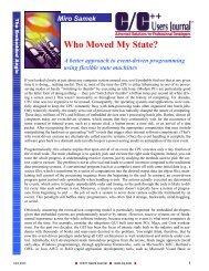
ST Microelectronics <strong>STR91x</strong> <strong>ARM</strong>9 microcontrollers. The actual hardware/software used in this <strong>QDK</strong><br />
is described below (see also Figure 1):<br />
J-Link USB<br />
Debugger<br />
QS trace data<br />
(UART0)<br />
LED/Peripheral<br />
Jumpers<br />
STR912F<br />
Target Device<br />
Two groups<br />
of user LEDs<br />
8 LEDs each<br />
USB to PC<br />
External<br />
power<br />
Power source<br />
selection Jumper<br />
Figure 1 <strong>IAR</strong> STR912-SK evaluation board with the J-Link JTAG pod.<br />
Copyright © <strong>Quantum</strong> <strong>Leaps</strong>, LLC. All Rights Reserved.<br />
1 of 20
<strong>QDK</strong><br />
ST Microelectronics <strong>STR91x</strong><br />
www.state-machine.com/arm<br />
1. <strong>IAR</strong> STR912-SK board with STR912F device (<strong>ARM</strong>966E-S core, 96KB RAM, 512KB ROM)<br />
2. The J-Link J-Tag pod from Segger (www.segger.com). NOTE: <strong>IAR</strong> Embedded Workbench supports<br />
also several other J-Tag pods<br />
3. <strong>IAR</strong> Embedded Workbench for <strong>ARM</strong> (EW<strong>ARM</strong>) KickStart edition version 6.30<br />
4. QP/C/C++ v4.3.00 or higher<br />
As shown in Figure 1, the STR912-SK board is connected via a 20-pin ribbon cable to the J-Link<br />
USB debugger. Additionally, the UART0 connector of the STR912-SK board is used in this <strong>QDK</strong> for<br />
QS (“Spy”) software tracing of the live QP applications. You need a straight serial cable with DB9<br />
connectors to connect UART0 to the COM port of your PC.<br />
1.1 What’s Included in the <strong>QDK</strong>?<br />
This <strong>QDK</strong> provides the Board Support Package (BSP) and two versions of the Dining Philosopher<br />
Problem (DPP) example application described in the Application Note “Dining Philosopher Problem<br />
Example” [AN DPP].<br />
1. DPP with the cooperative “Vanilla” kernel<br />
2. DPP with the preemptive run-to-completion QK kernel<br />
3. Application Note “QP and <strong>ARM</strong>7/<strong>ARM</strong>9” [AN QP and <strong>ARM</strong>]<br />
4. Application Note “Dining Philosopher Problem Example” [AN DPP]<br />
NOTE: This <strong>QDK</strong> covers both the C and C++ version of QP. The concrete code examples are<br />
taken from the C version, but the C++ version is essentially identical except for some trivial<br />
syntax differences.<br />
1.2 Licensing the <strong>QDK</strong><br />
The Generally Available (GA) distribution of this <strong>QDK</strong> available for download from the<br />
www.state-machine.com/arm website is offered with the following two licensing options:<br />
• The GNU General Public License version 2 (GPL) as published by the Free<br />
Software Foundation and appearing in the file GPL.TXT included in the packaging<br />
of every <strong>Quantum</strong> <strong>Leaps</strong> software distribution. The GPL open source license<br />
allows you to use the software at no charge under the condition that if<br />
you redistribute the original software or applications derived from it, the complete<br />
source code for your application must be also available under the conditions<br />
of the GPL (GPL Section 2[b]).<br />
• One of several <strong>Quantum</strong> <strong>Leaps</strong> commercial licenses, which are designed for customers<br />
who wish to retain the proprietary status of their code and therefore<br />
cannot use the GNU General Public License. The customers who license<br />
<strong>Quantum</strong> <strong>Leaps</strong> software under the commercial licenses do not use the software<br />
under the GPL and therefore are not subject to any of its terms.<br />
For more information, please visit the licensing section of our website at:<br />
www.state-machine.com/licensing.<br />
Copyright © <strong>Quantum</strong> <strong>Leaps</strong>, LLC. All Rights Reserved.<br />
2 of 20
<strong>QDK</strong><br />
ST Microelectronics <strong>STR91x</strong><br />
www.state-machine.com/arm<br />
2 Getting Started<br />
This section describes how to install, build, and use the <strong>QDK</strong>. This information is intentionally included<br />
early in this document, so that you could start using the <strong>QDK</strong> as soon as possible.<br />
NOTE: This <strong>QDK</strong> assumes that the standard QP distribution, consisting of QEP, QF, QK, and<br />
QS, has been installed, before installing this <strong>QDK</strong>. It is also strongly recommended that you<br />
read the QP Tutorial (www.quantum-leaps.com/doxygen/qpc/tutorial_page.html) before you<br />
start experimenting with this <strong>QDK</strong>.<br />
2.1 Installation<br />
This section describes how to install, build, and use the <strong>QDK</strong>-<strong>ARM</strong>-<strong>IAR</strong>_<strong>STR91x</strong> based on two versions<br />
of an example application.<br />
This document describes the standard <strong>QDK</strong> distribution, which must be augmented with the generic<br />
<strong>ARM</strong> code accompanying the Application Note “QP and <strong>ARM</strong>7/<strong>ARM</strong> with <strong>IAR</strong> Toolset” [QL 08a] and<br />
the standard distributions of the QP components. You need to download the following archives and<br />
unzip all of them into the same directory of your choice. This directory will be referred to as QP<br />
root directory and denoted :<br />
/<br />
- QP root directory (qpcpp for QP/C++)<br />
|<br />
+-include/<br />
- QP public include files<br />
| +-qassert.h – <strong>Quantum</strong> Assertions platform-independent public include<br />
| +-qep.h – QEP platform-independent public include<br />
| +-qf.h – QF platform-independent public include<br />
| +-qequeue.h – native QF event queue include<br />
| +-qmpool.h – native QF memory pool include<br />
| +-qpset.h – native QF priority set include<br />
|<br />
+-ports/<br />
- QP ports<br />
| +-arm/ - <strong>ARM</strong> port<br />
| | +-vanilla/ - “vanilla” ports<br />
| | | +-iar/ - <strong>IAR</strong> compiler<br />
| | | | +-dbg/ - QP libraries – Debug configuration<br />
| | | | | +-qep_<strong>ARM</strong>966E-S.a - QEP library<br />
| | | | | +-qf_<strong>ARM</strong>966E-S.a - QF library<br />
| | | | +-rel/ - QP libraries – Release configuration<br />
| | | | +-spy/ - QP libraries – Spy configuration<br />
| | | | +-make_<strong>ARM</strong>966E-S.bat - make script for building QP libraries (<strong>ARM</strong>966E-S core)<br />
| | | | +-qep_port.h - QEP port<br />
| | | | +-qf_port.h - QF port to <strong>ARM</strong><br />
| | | | +-qs_port.h - QS port<br />
| | | | +-qp_port.h - QP port<br />
| | |<br />
| | +-qk/ - QK ports<br />
| | | +-iar/ - <strong>IAR</strong> compiler<br />
| | | | +-dbg/ - QP libraries – Debug configuration<br />
| | | | | +-qep_<strong>ARM</strong>966E-S.a - QEP library<br />
| | | | | +-qf_<strong>ARM</strong>966E-S.a - QF library<br />
| | | | | +-qk_<strong>ARM</strong>966E-S.a - QK library<br />
| | | | +-rel/ - QP libraries – Release configuration<br />
| | | | +-spy/ - QP libraries – Spy configuration<br />
| | | | +-make_<strong>ARM</strong>966E-S.bat - make script for building QP libraries (<strong>ARM</strong>966E-S core)<br />
| | | | +-qep_port.h - QEP port<br />
| | | | +-qf_port.h - QF port to <strong>ARM</strong><br />
| | | | +-qk_port.h - QK port to <strong>ARM</strong><br />
Copyright © <strong>Quantum</strong> <strong>Leaps</strong>, LLC. All Rights Reserved.<br />
3 of 20
<strong>QDK</strong><br />
ST Microelectronics <strong>STR91x</strong><br />
www.state-machine.com/arm<br />
| | | | +-qs_port.h - QS port<br />
| | | | +-qp_port.h - QP port<br />
|<br />
+-examples/<br />
- subdirectory containing the examples<br />
| +-arm/ - <strong>ARM</strong> examples<br />
| | +-vanilla/ - “Vanilla” port<br />
| | | +-iar/ - <strong>IAR</strong> <strong>ARM</strong> compiler<br />
| | | | +-dpp-at91sam7s-ek – DPP example for the AT91SAM7S-EK evaluation board<br />
| | | | | +-dbg/ – Debug build (runs from RAM)<br />
| | | | | | +-dpp.out – executable image<br />
| | | | | +-rel/ – Release build (runs from Flash)<br />
| | | | | | +-dpp.out – executable image<br />
| | | | | +-spy/ – Spy build (runs from RAM)<br />
| | | | | | +-dpp.out – executable image (instrumented with QSpy)<br />
| | | | | +-at91mc_cstartup.s – AT91 startup code in assembly<br />
| | | | | +-at91SAM7S64.icf – <strong>IAR</strong> <strong>ARM</strong> linker command file<br />
| | | | | +-bsp.h - Board Support Package include file<br />
| | | | | +-bsp.c - Board Support Package implementation<br />
| | | | | +-dpp.h<br />
| | | | | +-main.c<br />
| | | | | +-philo.c<br />
| | | | | +-table.c<br />
| | | | | +-dpp.ewp – <strong>IAR</strong> project for the DPP application example<br />
| | | | | +-dpp.eww – <strong>IAR</strong> workspace for the DPP application example<br />
| | | |<br />
| | +-qk/ - QK (<strong>Quantum</strong> Kernel) port<br />
| | | +-iar/ - <strong>IAR</strong> <strong>ARM</strong> compiler<br />
| | | | +-dpp-at91sam7s-ek – DPP example for the AT91SAM7S-EK evaluation board<br />
| | | | | +-. . . – the same files as in vanilla/iar/dpp-at91sam7s<br />
| . . .<br />
Listing 1 Selected QP directories and files after installing <strong>QDK</strong>-<strong>ARM</strong>_<strong>IAR</strong>_<strong>STR91x</strong>. The<br />
highlighted elements are included the files included in <strong>QDK</strong>-<strong>ARM</strong>_<strong>IAR</strong>_<strong>STR91x</strong>.<br />
2.2 Building the QP Libraries<br />
All QP components are deployed as static libraries that you link to your application. The pre-built<br />
libraries for QEP, QF, QS, and QK are provided in the <strong>QDK</strong> code. The Application Note “QP and<br />
<strong>ARM</strong>7/<strong>ARM</strong> with <strong>IAR</strong> Toolset” [QL 08a] describes the process of building the QP libraries.<br />
2.3 Building the Examples<br />
The examples included in this <strong>QDK</strong> are based on the standard Dining Philosopher Problem implemented<br />
with active objects (see Chapter 9 in [PSiCC2]).<br />
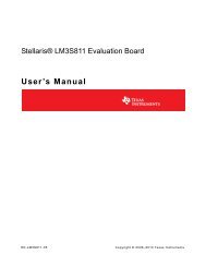
The example directory contains the <strong>IAR</strong> Embedded Workbench workspace file dpp.eww that you can<br />
load into the <strong>IAR</strong> EW IDE (see Figure 2). The workspace contains three build configurations (Debug,<br />
Release, and Spy) that you can select with the drop-down list, as shown in Figure 2.<br />
Copyright © <strong>Quantum</strong> <strong>Leaps</strong>, LLC. All Rights Reserved.<br />
4 of 20
<strong>QDK</strong><br />
ST Microelectronics <strong>STR91x</strong><br />
www.state-machine.com/arm<br />
Select build<br />
configuration<br />
Figure 2 <strong>IAR</strong> Embedded Workbench with the dpp-freertos.eww workspace.<br />
2.4 Running the Examples<br />
As mentioned before, this <strong>QDK</strong> contains two example applications for the STR912-SK board. Both<br />
of these examples require setting up the jumpers as shown in Figure 1 and in greater detail in Figure<br />
3.<br />
LEDs connected to GPIO6<br />
Peripherals (e.g., UARTs ) connected to GPIO3<br />
LED 16<br />
LED 15<br />
LED 14<br />
LED 13<br />
LED 12<br />
LED 11<br />
LED 10<br />
LED 9<br />
LED 8<br />
LED 7<br />
LED 6<br />
LED 5<br />
LED 4<br />
LED 3<br />
LED 2<br />
LED 1<br />
Figure 3 LED/Peripheral jumper setting on the STR912-SK board.<br />
Copyright © <strong>Quantum</strong> <strong>Leaps</strong>, LLC. All Rights Reserved.<br />
5 of 20
2.4.1 Dining Philosopher Problem (DPP) Example Application<br />
<strong>QDK</strong><br />
ST Microelectronics <strong>STR91x</strong><br />
www.state-machine.com/arm<br />
The DPP application blinks the user LEDs 9-13 (see Figure 1) to indicate the changing status of the<br />
Dining Philosophers. Additionally LED 15 should blink once per second with 50% duty cycle. LED 16<br />
is toggled from the idle processing and its intensity is proportional to the frequency of idle task.<br />
If you downloaded the Spy build configuration to the target board and connected the UAR0 of the<br />
STR912-SK board to the COM port on your PC, you could launch the QSPY host utility to observe<br />
the output in the human-readable format. You launch the QSPY utility on a Windows PC as follows.<br />
Change the directory to the QSPY host utility \tools\qspy\win32\mingw\rel and execute:<br />
qspy –c COM1 –b 115200<br />
This will start the QSPY host application to listen on COM1 serial port with baud rate 115200.<br />
(Please use the actual COM port number on your PC.) The following screen shot shows the QSPY<br />
output from the DPP run:<br />
command-line<br />
options used<br />
timestamp<br />
QS trace record<br />
Figure 4 Screen shot from the QSPY output.<br />
Copyright © <strong>Quantum</strong> <strong>Leaps</strong>, LLC. All Rights Reserved.<br />
6 of 20
<strong>QDK</strong><br />
ST Microelectronics <strong>STR91x</strong><br />
www.state-machine.com/arm<br />
3 Board Support Package<br />
The Board Support Package (BSP) for the STR912-SK board is co-located with the DPP example applications<br />
and consists of the following files:<br />
• s91x_init.s — startup code in assembly provided by ST Microelectronics<br />
• 91x_vect_qp.s — interrupt vector table for QP<br />
• <strong>STR91x</strong>library\ — directory with code for peripherals of the ST91x microcontroller family<br />
provided by ST Microelectronics<br />
• 91x_conf.h — configuration for the <strong>STR91x</strong>library used in the DPP example (you need to customize<br />
for your application)<br />
• 91x_it.c — dummy definitions of all interrupt handlers for ST91x (you need to re-define interrupts<br />
that you use in your application)<br />
• <strong>STR91x</strong>_FLASH.icf — linker command file to link the code to Flash (default)<br />
• <strong>STR91x</strong>_RAM.icf — alternative linker command file to link the code to RAM (for debugging only)<br />
• bsp.c — BSP functions and ISRs in C<br />
• bsp.h — BSP header file<br />
The BSP does not initialize all <strong>STR91x</strong> peripherals. However, it should be fairly complete in that it<br />
supports code downloading to Flash, software tracing with <strong>Quantum</strong> Spy (QS), fine-tuning of the<br />
release version, and more.<br />
3.1 Startup Code in Assembly<br />
The customized startup sequence for the <strong>STR91x</strong> is implemented in the assembly file s91x_init.s<br />
co-located with the DPP example application. This file is provided by ST Microelectronics and includes<br />
the following steps:<br />
• Enabling the Buffered mode<br />
• Remapping Flash Bank 0 at address 0x0 and Bank 1 at address 0x80000, when the bank 0 is<br />
the boot bank, then also enabling Bank 1<br />
• Configuring 96K RAM, PFQBC enabled, DTCM & AHB wait-states disabled<br />
• Configuring 96 MHZ PLL clock as the default frequency<br />
• Initialization of all <strong>ARM</strong> Stack pointer registers (such as USER/SYSTEM, IRQ, FIQ, SVC, UNDEF,<br />
ABORT)<br />
NOTE: The standard QP port to <strong>ARM</strong>7/<strong>ARM</strong>9 uses only the USER/SYSTEM stack. All other<br />
stacks should be set to zero size for this <strong>QDK</strong>.<br />
You need to customize the assembly file s91x_init.s only if you want to change the basic configuration<br />
of the processor. Otherwise, you should have not need to touch this file.<br />
Copyright © <strong>Quantum</strong> <strong>Leaps</strong>, LLC. All Rights Reserved.<br />
7 of 20
<strong>QDK</strong><br />
ST Microelectronics <strong>STR91x</strong><br />
www.state-machine.com/arm<br />
3.1.1 Interrupt Vector Table<br />
(1) SECTION .intvec:CODE:ROOT(2)<br />
PUBLIC __vector<br />
IMPORT __iar_program_start<br />
IMPORT QF_undef<br />
IMPORT QF_swi<br />
IMPORT QF_pAbort<br />
IMPORT QF_dAbort<br />
IMPORT QF_reserved<br />
IMPORT QF_irq<br />
IMPORT QF_fiq<br />
(2) CODE32<br />
(3) __vector:<br />
(4) LDR PC,=__iar_program_start<br />
LDR PC,=QF_undef<br />
LDR PC,=QF_swi<br />
LDR PC,=QF_pAbort<br />
LDR PC,=QF_dAbort<br />
LDR PC,=QF_reserved<br />
LDR PC,=QF_irq<br />
LDR PC,=QF_fiq<br />
LTORG<br />
END<br />
Listing 2 Interrupt Vector Table defined in the 91x_vect_qp.s module.<br />
(1) This module defines interrupt vectors and is placed in the .intvec section.<br />
(2) The <strong>ARM</strong> core always starts in <strong>ARM</strong> state.<br />
(3) The symbol __vector denotes the beginning the primary vector table.<br />
(4) The primary vector table is pre-filled with direct jumps to the exception handlers defined in QP<br />
port to <strong>ARM</strong> (see Application Note “QP and <strong>ARM</strong>” [QP-<strong>ARM</strong> 08] included in this <strong>QDK</strong>).<br />
NOTE: All QP exception handlers such as QF_undef, QF_swi, … QF_irq, and QF_fiq always perform<br />
a mode switch to the SYSTEM mode, and call the C-level code in this mode. In particu -<br />
lar, the QP exception handlers never use the stack pointers of the various <strong>ARM</strong> modes and<br />
therefore you don’t need to setup these stacks.<br />
3.2 Linker Command File<br />
A linker command file controls where the linker will locate the code and data in memory. The BSP<br />
for the STR912-SK board comes with the file <strong>STR91x</strong>_FLASH.icf to place the complete application<br />
image in the Flash ROM. This file is not intended for manual editing, but rather only via the <strong>IAR</strong><br />
Embedded Workbench IDE, as shown in Figure 5.<br />
Copyright © <strong>Quantum</strong> <strong>Leaps</strong>, LLC. All Rights Reserved.<br />
8 of 20
<strong>QDK</strong><br />
ST Microelectronics <strong>STR91x</strong><br />
www.state-machine.com/arm<br />
Browse for the<br />
linker file<br />
Select<br />
Linker<br />
Edit the linker<br />
configuration file<br />
Adjust the CSTACK<br />
(USER/SYSTEM stack)<br />
Figure 5 Adjusting the stack sizes in the <strong>IAR</strong> Embedded Workbench IDE.<br />
Typically, you don’t need to adjust the memory addresses for the <strong>ARM</strong> device (in the Memory Re -<br />
gions tab in Figure 5), because they come pre-configured when you select the specific device in the<br />
General Options section. However, you should adjust the Stack and Heap Sizes on the third tab of<br />
the “Linker configuration file editor” shown in Figure 5. Again, note that QP uses only the<br />
USER/SYSTEM stack and does not use any other stacks. If you don’t use the heap, which is highly<br />
recommended in any embedded application, you should also set the size of the heap to zero.<br />
3.3 <strong>ARM</strong>/THUMB Compilation<br />
A very important and often overlooked aspect for optimal system performance is controlling both<br />
the instruction set chosen to compile individual modules. This <strong>QDK</strong> gives you the freedom of choosing<br />
between <strong>ARM</strong> and THUMB instruction sets for most of the modules.<br />
Generally, the code that must frequently disable/enable interrupts runs faster when compiled to<br />
<strong>ARM</strong>, because the THUMB instruction set does not contain the MSR/MRS instructions necessary to<br />
disable interrupts at the <strong>ARM</strong> core level (so costly mode switches must occur in the THUMB code).<br />
On the other hand, the application-level code executes faster when compiled to THUMB, due to<br />
better code density.<br />
Copyright © <strong>Quantum</strong> <strong>Leaps</strong>, LLC. All Rights Reserved.<br />
9 of 20
<strong>QDK</strong><br />
ST Microelectronics <strong>STR91x</strong><br />
www.state-machine.com/arm<br />
The <strong>IAR</strong> project file for the DPP application places the application code in a separate folder than the<br />
startup code. Therefore it is easy to override the compilation options separately for the Application<br />
folder and the other code. Currently, the Application folder is compiled to THUMB.<br />
3.4 BSP Functions in C<br />
The file bsp.c located in the directory \examples\arm\vanilla\iar\dpp-str912-sk contains the<br />
ISRs, the initialization, and the QS port to the STR912-SK board. The file bsp.c uses the facility<br />
provided in the subdirectory <strong>STR91x</strong>library\ provided by ST Microelectronics.<br />
3.4.1 The Board Initialization<br />
The board initialization is performed in the BSP_init() function called from main().<br />
void BSP_init(void) {<br />
GPIO_InitTypeDef GPIO_InitStruct;<br />
uint8_t n;<br />
(1) WDG_Cmd(DISABLE);<br />
(2) SCU_PCLKDivisorConfig(SCU_PCLK_Div2); /* peripheral bus clokdivisor = 2 */<br />
/* GPIO 6 clock source enable, used by the LEDs */<br />
(3) SCU_APBPeriphClockConfig(__GPIO6, ENABLE);<br />
/* enable VIC clock */<br />
SCU_AHBPeriphClockConfig(__VIC, ENABLE);<br />
SCU_AHBPeriphReset(__VIC, DISABLE);<br />
VIC_DeInit();<br />
VIC0->DVAR = (uint32_t)&ISR_spur; /* install spurious handler for VIC0 */<br />
VIC1->DVAR = (uint32_t)&ISR_spur; /* install spurious handler for VIC1 */<br />
for (n = 0; n < 32; ++n) {<br />
VIC_ITCmd(n, DISABLE);<br />
}<br />
/* configure GPIO6 to drive the LED's... */<br />
(4) GPIO_DeInit(GPIO6);<br />
GPIO_InitStruct.GPIO_Direction = GPIO_PinOutput;<br />
GPIO_InitStruct.GPIO_Pin<br />
= GPIO_Pin_All;<br />
GPIO_InitStruct.GPIO_Type = GPIO_Type_PushPull;<br />
GPIO_InitStruct.GPIO_IPConnected = GPIO_IPConnected_Disable;<br />
GPIO_InitStruct.GPIO_Alternate = GPIO_OutputAlt1;<br />
GPIO_Init(GPIO6, &GPIO_InitStruct);<br />
(5) if (QS_INIT((void *)0) == 0) { /* initialize the QS software tracing */<br />
Q_ERROR();<br />
}<br />
}<br />
Listing 3 BSP initialization<br />
(1) The <strong>STR91x</strong> Watchdog is disabled – you can have a different policy in your application<br />
(2) The peripheral clock divisor is selected – you can use a different divisor in your application<br />
(3) <strong>STR91x</strong> requires explicitly enabling the clock to all used peripherals<br />
NOTE: If you forget to enable the clock, the peripheral won’t work!<br />
Copyright © <strong>Quantum</strong> <strong>Leaps</strong>, LLC. All Rights Reserved.<br />
10 of 20
<strong>QDK</strong><br />
ST Microelectronics <strong>STR91x</strong><br />
www.state-machine.com/arm<br />
(4) The GPIO pins for the LEDs 9-16 (GPIO port 6) are configured.<br />
NOTE: LEDs 1-8 are not used, because the pins are needed for the UART serial port (see Figure<br />
3).<br />
(5) Initialize the QS software tracing (this code is active only when the macro Q_SPY is defined).<br />
3.4.2 The ISRs<br />
The Interrupt Service Routines and the initialization of interrupts is the only part of the BSP dependent<br />
on the QF port type. The following subsections discuss the ISRs for the three QF ports included<br />
in this <strong>QDK</strong>.<br />
3.4.2.1 ISRs in the Vanilla Port<br />
(1) typedef void (*IntVector)(void); /* IntVector pointer-to-function */<br />
(2) __arm void BSP_irq(void) {<br />
(3) IntVector vect = (IntVector)VIC0->VAR; /* read the VAR from VIC0 */<br />
(4) IntVector vect1 = (IntVector)VIC1->VAR; /* read the VAR from VIC1 */<br />
(5) QF_INT_ENABLE(); /* allow nesting interrupts */<br />
(6) (*vect)(); /* call the IRQ ISR via the pointer to function */<br />
(7) QF_INT_DISABLE(); /* disable interrups for the exit sequence */<br />
(8) VIC0->VAR = 0; /* send End-Of-Interrupt to VIC0 */<br />
(9) VIC1->VAR = 0; /* send End-Of-Interrupt to VIC1 */<br />
}<br />
/*..........................................................................*/<br />
(10) __arm void BSP_fiq(void) {<br />
/* TBD: implement the FIQ handler directly right here, see NOTE02 */<br />
/* NOTE: Do NOT enable interrupts throughout the whole FIQ processing. */<br />
/* NOTE: Do NOT write EOI to the AIC */<br />
}<br />
/* ISRs --------------------------------------------------------------------*/<br />
(11) __arm void TIM3_IRQHandler(void) {<br />
(12) TIM3->OC1R += BSP_TIM3_PERIOD - 1; /* set the output compare register */<br />
(13) TIM3->SR &= ~TIM_IT_OC1; /* clear interrupt source (Timer3) */<br />
#ifdef Q_SPY<br />
{<br />
uint16_t currTime16 = (uint16_t)TIM3->CNTR;<br />
l_currTime32 += (currTime16 - l_prevTime16) & 0xFFFF;<br />
l_prevTime16 = currTime16;<br />
}<br />
#endif<br />
(14) QF_tick(); /* process all arm time events (timers) */<br />
}<br />
/*..........................................................................*/<br />
(15) static __arm void ISR_spur(void) {<br />
}<br />
/*..........................................................................*/<br />
(16) __arm void QF_onStartup(void) {<br />
TIM_InitTypeDef TIM_InitStruct;<br />
(17) SCU_APBPeriphClockConfig(__TIM23, ENABLE);<br />
TIM_DeInit(TIM3);<br />
Copyright © <strong>Quantum</strong> <strong>Leaps</strong>, LLC. All Rights Reserved.<br />
11 of 20
<strong>QDK</strong><br />
ST Microelectronics <strong>STR91x</strong><br />
www.state-machine.com/arm<br />
TIM_StructInit(&TIM_InitStruct);<br />
TIM_InitStruct.TIM_Mode<br />
= TIM_OCM_CHANNEL_1;<br />
TIM_InitStruct.TIM_OC1_Modes = TIM_TIMING;<br />
TIM_InitStruct.TIM_Clock_Source = TIM_CLK_APB;<br />
TIM_InitStruct.TIM_Clock_Edge = TIM_CLK_EDGE_RISING;<br />
TIM_InitStruct.TIM_Prescaler = BSP_TIM3_PRESCALER - 1;<br />
TIM_InitStruct.TIM_Pulse_Level_1 = TIM_HIGH;<br />
(18) TIM_InitStruct.TIM_Pulse_Length_1 = BSP_TIM3_PERIOD - 1;<br />
TIM_Init(TIM3, &TIM_InitStruct);<br />
}<br />
/* configure the VIC for the TIM3 interrupt */<br />
VIC_Config(TIM3_ITLine, VIC_IRQ, BSP_TICK_PRIO);<br />
VIC_ITCmd(TIM3_ITLine, ENABLE);<br />
TIM_ITConfig(TIM3, TIM_IT_OC1, ENABLE);<br />
TIM_CounterCmd(TIM3, TIM_CLEAR);<br />
TIM_CounterCmd(TIM3, TIM_START);<br />
Listing 4 The ISR definitions and initialization for the Vanilla port (\examples\arm\-<br />
vanilla\iar\dpp-at91sam7s-ek\bsp.c).<br />
(1) This typedef defines the pointer-to-function type for calling the interrupt handlers.<br />
(2) As described in Application Note “QP and <strong>ARM</strong>7/<strong>ARM</strong> with <strong>IAR</strong> Toolset” [QL 08a], the low-level<br />
IRQ interrupt “wrapper” in assembly calls function BSP_irq(). This function is a regular C function<br />
(not an __irq function!) and can be compiled to THUMB or <strong>ARM</strong>, as you like. Here, the<br />
function BSP_irq() is defined as an <strong>ARM</strong> function (via the __arm keyword) to be able to use the<br />
very efficient, unconditional interrupt disabling and enabling macros QF_INT_DISABLE()/<br />
QF_INT_ENABLE(). The __ramfunc extended keyword makes the function to execute from the<br />
RAM, which is only done for better performance.<br />
(3) The current interrupt vector is always loaded from the VIC0 VAR register into a temporary variable.<br />
(4) The VIC1 VAR register is also read to clear the interrupt.<br />
NOTE: <strong>STR91x</strong> has two chained Vectored Interrupt Controllers (VIC0 and VIC1). The current<br />
vector address is always available from VIC0.<br />
(5) Interrupts are enabled unconditionally at the <strong>ARM</strong> core level by means of the macro QF_INT_EN-<br />
ABLE().<br />
NOTE: Enabling all IRQs and FIQs is safe, because the AIC performs interrupt prioritization in<br />
hardware.<br />
(6) The interrupt handler is invoked via the pointer-to-function (vector address) extracted from the<br />
AIC. Please note that the vectoring capability of the AIC is actually used, even though this is<br />
not the traditional auto-vectoring. For the vectoring to work, the VIC VAR registers must be initialized<br />
with the addresses of interrupt handlers, such as the time tick ISR TIM3_IRQHandler().<br />
NOTE: The ST Microelectronics library initializes the appropriate VIC VAR register with the address<br />
of the corresponding handler routine when you configure the interrupt.<br />
Copyright © <strong>Quantum</strong> <strong>Leaps</strong>, LLC. All Rights Reserved.<br />
12 of 20
<strong>QDK</strong><br />
ST Microelectronics <strong>STR91x</strong><br />
www.state-machine.com/arm<br />
(7) After ISR function returns, the interrupts are disabled unconditionally at the <strong>ARM</strong> core level by<br />
means of the macro QF_INT_ENABLE().<br />
(8) The EOI command is written to the VIC0, which informs the interrupt controller that the interrupt<br />
processing has ended.<br />
(9) The EOI command is written to the VIC0, which informs the interrupt controller that the interrupt<br />
processing has ended.<br />
(10) As described in Application Note “QP and <strong>ARM</strong>7/<strong>ARM</strong> with <strong>IAR</strong> Toolset” [QL 08a], the low-level<br />
FIQ interrupt “wrapper” in assembly calls function BSP_fiq(). This function is a regular C function<br />
(not an __fiq function!) and can be compiled to THUMB or <strong>ARM</strong>, as you like. Here, the<br />
function BSP_fiq() is defined as __ramfunc to execute from the RAM, which is only done for better<br />
performance. Because the VICs do not provide priority controller for the FIQ (see the<br />
“<strong>STR91x</strong>FA <strong>ARM</strong>9®-based microcontroller family”) there is really not any value added by indirecting<br />
via the VIC VAR register. The body of the interrupt might as well be directly implemented<br />
in BSP_fiq().<br />
NOTE: Because the VICs does not protect the FIQ line with the priority controller, the whole<br />
work of FIQ should be performed with interrupts permanently locked at the <strong>ARM</strong> core level.<br />
In particular, the IRQ interrupt should never be unlocked during FIQ processing.<br />
(11) As described at Listing 4(6), the interrupt handler is a regular C function.<br />
(12) This BSP uses TIM3 timer as the source for the system clock tick interrupt. TIM3 is a freerunning<br />
counter, and consequently the output compare register is incremented to interrupt<br />
again in the desired period.<br />
(13) The interrupt source (TIM3 in this case) must be cleared.<br />
NOTE: Please note that the interrupt handler executes with interrupt unlocked at the <strong>ARM</strong><br />
core level. However, the prioritization performed in AIC prevents the same (or any other<br />
lower-priority) interrupt from preempting the currently serviced interrupt.<br />
(14) The work of the interrupt is performed, which consists of the system clock tick processing<br />
QF_tick() in this case.<br />
(15) The spurious interrupt handler is empty.<br />
(16) The QF callback QF_onStartup() is called just before entering the background loop of the<br />
“vanilla” QF port (see Chapter 7 in [PSiCC2]). This purpose of the QF_onStartup() function is to<br />
configure and enable the interrupts.<br />
(17) The clock for the Timers 2-3 is enabled.<br />
(18) The TIM3 register is initialized to interrupt in the desired period. The macro BSP_TIM3_PERIOD is<br />
defined as follows:<br />
#define BSP_TIM3_PERIOD \<br />
(BSP_CPU_PERIPH_HZ / BSP_TIM3_PRESCALER / BSP_TICKS_PER_SEC)<br />
Copyright © <strong>Quantum</strong> <strong>Leaps</strong>, LLC. All Rights Reserved.<br />
13 of 20
3.4.2.2 ISRs in the QK Port<br />
<strong>QDK</strong><br />
ST Microelectronics <strong>STR91x</strong><br />
www.state-machine.com/arm<br />
The ISRs in the QK port are defined and initialization identically as in the “vanilla” port. The only<br />
difference is that you use the QK “wrapper” functions for interrupts and other exceptions instead of<br />
QF functions. The following subsections discuss the ISRs for the QK port included in this <strong>QDK</strong>.<br />
SECTION .intvec:CODE:ROOT(2)<br />
PUBLIC __vector<br />
IMPORT __iar_program_start<br />
IMPORT QF_undef<br />
IMPORT QF_swi<br />
IMPORT QF_pAbort<br />
IMPORT QF_dAbort<br />
IMPORT QF_reserved<br />
IMPORT QK_irq<br />
IMPORT QK_fiq<br />
CODE32<br />
__vector:<br />
LDR<br />
LDR<br />
LDR<br />
LDR<br />
LDR<br />
LDR<br />
LDR<br />
LDR<br />
PC,=__iar_program_start<br />
PC,=QF_undef<br />
PC,=QF_swi<br />
PC,=QF_pAbort<br />
PC,=QF_dAbort<br />
PC,=QF_reserved<br />
PC,=QK_irq<br />
PC,=QK_fiq<br />
LTORG<br />
END<br />
Listing 5 The Interrupt Vector Table definition for the QK port (\examples\arm\qk\-<br />
iar\dpp-str912-sk\91x_vect_qp.s).<br />
Copyright © <strong>Quantum</strong> <strong>Leaps</strong>, LLC. All Rights Reserved.<br />
14 of 20
4 The <strong>Quantum</strong> Spy (QS) Instrumentation<br />
<strong>QDK</strong><br />
ST Microelectronics <strong>STR91x</strong><br />
www.state-machine.com/arm<br />
This <strong>QDK</strong> demonstrates how to use the <strong>Quantum</strong> Spy (QS) to generate real-time trace of a running<br />
QP application. Normally, the QS instrumentation is inactive and does not add any overhead to<br />
your application, but you can turn the instrumentation on by defining the Q_SPY macro and recompiling<br />
the code.<br />
<strong>Quantum</strong> Spy (QS) is a software tracing facility built into all QP components and also available to<br />
the Application code. QS allows you to gain unprecedented visibility into your application by selectively<br />
logging almost all interesting events occurring within state machines, the framework, the kernel,<br />
and your application code. QS software tracing is minimally intrusive, offers precise timestamping,<br />
sophisticated runtime filtering of events, and good data compression (see Chapter 11 in<br />
PSiCC2 [PSiCC2]).<br />
QS can be configured to send the real-time data out of the serial port of the target device. On the<br />
STR912F MCU, QS uses the built-in USART0 to send the trace data out (see Figure 1), so the QSPY<br />
host application can conveniently receive the trace data on the host PC. The complete implementation<br />
of the QS software-tracing output consists of several steps, which are all summarized in Listing<br />
6 (file bsp.c).<br />
(1) #ifdef Q_SPY<br />
(2) static uint32_t l_currTime32;<br />
(3) static uint16_t l_prevTime16;<br />
(4) enum AppRecords { /* application-specific trace records */<br />
PHILO_STAT = QS_USER<br />
};<br />
#endif<br />
/*--------------------------------------------------------------------------*/<br />
#ifdef Q_SPY<br />
(5) uint8_t QS_onStartup(void const *arg) {<br />
(6) static uint8_t qsBuf[BSP_QS_BUF_SIZE]; /* buffer for <strong>Quantum</strong> Spy */<br />
GPIO_InitTypeDef GPIO_InitStruct;<br />
UART_InitTypeDef UART_InitStruct;<br />
(7) QS_initBuf(qsBuf, sizeof(qsBuf));<br />
/* configure the UART0 for QSPY output ... */<br />
(8) SCU_APBPeriphClockConfig(__UART0, ENABLE); /* enable clock for UART0 */<br />
(9) SCU_APBPeriphClockConfig(__GPIO3, ENABLE); /* enable clock for GPIO3 */<br />
(10) SCU_APBPeriphReset(__UART0, DISABLE); /* remove UART0 from reset */<br />
(11) SCU_APBPeriphReset(__GPIO3, DISABLE); /* remove GPIO3 from reset */<br />
/* configure UART0_TX pin GPIO3.4 ... */<br />
(12) GPIO_DeInit(GPIO3);<br />
GPIO_InitStruct.GPIO_Pin<br />
= GPIO_Pin_4;<br />
GPIO_InitStruct.GPIO_Direction = GPIO_PinOutput;<br />
GPIO_InitStruct.GPIO_Type = GPIO_Type_PushPull;<br />
GPIO_InitStruct.GPIO_IPConnected = GPIO_IPConnected_Disable;<br />
GPIO_InitStruct.GPIO_Alternate = GPIO_OutputAlt3;<br />
GPIO_Init(GPIO3, &GPIO_InitStruct);<br />
/* configure UART0... */<br />
(13) UART_DeInit(UART0); /* force UART0 registers to reset values */<br />
UART_InitStruct.UART_WordLength = UART_WordLength_8D;<br />
UART_InitStruct.UART_StopBits = UART_StopBits_1;<br />
UART_InitStruct.UART_Parity = UART_Parity_No;<br />
UART_InitStruct.UART_BaudRate = BSP_QS_BAUD_RATE;<br />
UART_InitStruct.UART_HardwareFlowControl = UART_HardwareFlowControl_None;<br />
Copyright © <strong>Quantum</strong> <strong>Leaps</strong>, LLC. All Rights Reserved.<br />
15 of 20
<strong>QDK</strong><br />
ST Microelectronics <strong>STR91x</strong><br />
www.state-machine.com/arm<br />
UART_InitStruct.UART_Mode = UART_Mode_Tx;<br />
UART_InitStruct.UART_FIFO = UART_FIFO_Enable;<br />
UART_InitStruct.UART_TxFIFOLevel = UART_FIFOLevel_1_8;<br />
UART_InitStruct.UART_RxFIFOLevel = UART_FIFOLevel_1_8;<br />
UART_Init(UART0, &UART_InitStruct); /* initialize UART0 */<br />
UART_Cmd(UART0, ENABLE); /* enable UART0 */<br />
(14) QS_FILTER_ON(QS_ALL_RECORDS);<br />
QS_FILTER_OFF(...);<br />
...<br />
/* setup the QS filters... */<br />
(15) return (uint8_t)1; /* indicate successfull QS initialization */<br />
}<br />
/*..........................................................................*/<br />
(16) void QS_onCleanup(void) {<br />
}<br />
/*..........................................................................*/<br />
/* NOTE: getTime is invoked within a critical section (inetrrupts disabled) */<br />
(17) uint32_t QS_onGetTime(void) {<br />
(18) uint16_t currTime16 = (uint16_t)TIM3->CNTR;<br />
(19) l_currTime32 += (currTime16 - l_prevTime16) & 0xFFFF;<br />
(20) l_prevTime16 = currTime16;<br />
(21) return l_currTime32;<br />
}<br />
/*..........................................................................*/<br />
(22) void QS_onFlush(void) {<br />
uint16_t nBytes = BSP_UART_TX_FIFO; /* the capacity of the UART TX FIFO */<br />
uint8_t const *block;<br />
(23) while ((block = QS_getBlock(&nBytes)) != (uint8_t *)0) {<br />
(24) while ((UART0->FR & 0x80) == 0) { /* TX FIFO not empty? */<br />
} /* keep waiting... */<br />
(25) while (nBytes-- != 0) {<br />
UART0->DR = *block++; /* stick the byte to the TX FIFO */<br />
}<br />
nBytes = BSP_UART_TX_FIFO; /* for the next time around */<br />
}<br />
}<br />
#endif /* Q_SPY */<br />
/*--------------------------------------------------------------------------*/<br />
Listing 6 QS implementation to send data out of the UART0 of the STR912 device.<br />
(1) The QS instrumentation is enabled only when the macro Q_SPY is defined<br />
(2) The static l_currTime32 variable is used to hold the 32-bit-wide timestamp.<br />
(3) The static l_prevTime16 variable is used to hold the last 16-bit-wide reading of the free-running<br />
16-bit Timer 3 (the same used to generate the system clock tick interrupt).<br />
(4) This enumeration defines application-specific QS trace record(s), to demonstrate how to use<br />
them.<br />
(5) You need to define the QS_onStartup() callback to initialize the QS software tracing.<br />
(6) You should adjust the QS buffer size (in bytes) to your particular application<br />
(7) You always need to call QS_initBuf() from QS_onStartup() to initialize the trace buffer.<br />
(8-9) The clock to the UART0 peripheral is enabled. Also, the clock to the GPIO3 peripheral is enabled.<br />
GPIO3 controls the UART0 transmit and receive pins.<br />
(10-11) The UART0 and GPIO3 peripherals are removed from reset.<br />
Copyright © <strong>Quantum</strong> <strong>Leaps</strong>, LLC. All Rights Reserved.<br />
16 of 20
<strong>QDK</strong><br />
ST Microelectronics <strong>STR91x</strong><br />
www.state-machine.com/arm<br />
(12) The transmit pin GPIO3.4 is configured as output, alternative function 3 (UART0 Tx) using the<br />
ST driver library interface.<br />
(13) The UART0 is not properly configured using the ST driver library interface.<br />
(14) The QS filters are setup (see Chapter 11 in [PSiCC2] as well as “QP Reference Manual”<br />
online).<br />
(15) The QS_onStartup() callback returns 1, meaning that the QS initialization was successful.<br />
(16) The QS_onCleanup() callback is empty for MSP430 (the application never exits).<br />
(17-21) The QS_onGetTime() callback provides a fine-granularity timestamp. The timestamp is discussed<br />
in the next section.<br />
(22) The QS_onFlush() callback flushes the QS trace buffer to the host. Typically, the function busywaits<br />
for the transfer to complete. It is only used in the initialization phase for sending the QS<br />
dictionary records to the host.<br />
(23) The implementation of QS for STR912 uses the block-oriented QS-buffer interface QS_getBlock(),<br />
which provides up to 16 bytes to fill the FIFO of the UART (see Chapter 11 in [PSiCC2]).<br />
(24) The QS_onFlush() callback busy-waits in-line until the transmit buffer is empty.<br />
(25) The data byte is inserted into the UART0 data register.<br />
4.1 QS Time Stamp Callback QS_onGetTime()<br />
The platform-specific QS port must provide function QS_onGetTime() (Listing 6(17-21)) that returns<br />
the current time stamp in 32-bit resolution. To provide such a fine-granularity time stamp, the BSP<br />
uses the free running Timer 3, which is the same timer already used for generation of the system<br />
clock-tick interrupt.<br />
NOTE: The QS_onGetTime() callback is always called with interrupts locked.<br />
Figure 6 shows how the Timer 3 Count Register (TIM3->CNTR) reading is extended to 32 bits.<br />
The drawing below shows a free running Timer 3 Count Register (TIM3->CNTR) that counts up from<br />
0 to 0xFFFF and rolls over to 0. If the system tick rate is faster than the rollover rate then you<br />
could ‘oversample’ this free-running timer by reading it in the clock tick ISR, as shown in Listing 4.<br />
The 32-bit variable l_currTime32 contains the sum of the 16-bit deltas from each readout of the<br />
free running Timer 3 Count Register. Because of unsigned 16-bit arithmetic used in Listing 6(19),<br />
even a ‘small’ current value minus a ‘large’ previous value still results in the proper delta. Note that<br />
QS_onGetTime() can actually be called at just about any time and thus, also needs to update l_currTime32<br />
before it returns the current value.<br />
Copyright © <strong>Quantum</strong> <strong>Leaps</strong>, LLC. All Rights Reserved.<br />
17 of 20
<strong>QDK</strong><br />
ST Microelectronics <strong>STR91x</strong><br />
www.state-machine.com/arm<br />
count<br />
32-bit time stamp<br />
returned from<br />
QS_onGetTime()<br />
System<br />
clock tick<br />
period<br />
TIM3->CNTR<br />
Register<br />
0xFFFF<br />
0x0000<br />
System<br />
clock-tick<br />
time<br />
Figure 6 Using the Timer 3 Count Register to provide 32-bit QS time stamp.<br />
4.2 Invoking the QSpy Host Application<br />
The QSPY host application receives the QS trace data, parses it and displays on the host workstation<br />
(currently Windows or Linux). For the configuration options chosen in this port, you invoke the<br />
QSPY host application as follows (please refer to the QSPY section in the “QP Reference Manual”):<br />
qspy –c COM1 –b 115200<br />
Copyright © <strong>Quantum</strong> <strong>Leaps</strong>, LLC. All Rights Reserved.<br />
18 of 20
5 Related Documents and References<br />
<strong>QDK</strong><br />
ST Microelectronics <strong>STR91x</strong><br />
www.state-machine.com/arm<br />
Document<br />
[PSiCC2] “Practical UML Statecharts in C/C+<br />
+, Second Edition”, Miro Samek, Newnes,<br />
2008<br />
[QP-<strong>ARM</strong> 08] “QP and <strong>ARM</strong>7/<strong>ARM</strong>9”,<br />
<strong>Quantum</strong> <strong>Leaps</strong>, 2008<br />
[QL AN-DPP 08] “Application Note: Dining<br />
Philosophers Application”, <strong>Quantum</strong> <strong>Leaps</strong>,<br />
LLC, 2008<br />
[QP/C 08] “QP/C Reference Manual”,<br />
<strong>Quantum</strong> <strong>Leaps</strong>, LLC, 2008<br />
[QP/C++ 08] “QP/C++ Reference Manual”,<br />
<strong>Quantum</strong> <strong>Leaps</strong>, LLC, 2008<br />
[QL AN-Directory 07] “Application Note: QP<br />
Directory Structure”, <strong>Quantum</strong> <strong>Leaps</strong>, LLC,<br />
2007<br />
[<strong>IAR</strong> 08a] “<strong>ARM</strong>® <strong>IAR</strong> C/C++ Compiler Reference<br />
Guide”, <strong>IAR</strong> 08<br />
[<strong>IAR</strong> 08b] “<strong>IAR</strong> Linker and Library Tools Reference<br />
Guide”, <strong>IAR</strong> 08<br />
[<strong>IAR</strong> 08c] “<strong>ARM</strong>® Embedded Workbench®<br />
IDE User Guide”, <strong>IAR</strong> 08<br />
[ST 08] “<strong>STR91x</strong>FA <strong>ARM</strong>9®-based microcontroller<br />
family”, ST Microelectronics, April 2008<br />
Location<br />
http://www.state-machine.com/doc/AN_DPP.pdf<br />
(included in this <strong>QDK</strong>)<br />
http://www.state-machine.com/doxygen/qpc/<br />
http://www.state-machine.com/doxygen/qpcpp/<br />
Available from most online book retailers, such as<br />
amazon.com. See also: http://www.state-machine.com/psicc2.htm<br />
http://www.statemachine.com/doc/AN_QP_and_<strong>ARM</strong>.pdf<br />
http://www.state-machine.com/doc/AN_QP_Directory_Structure.pdf<br />
Available in PDF as part of the <strong>ARM</strong> KickStart kit<br />
in the file EW<strong>ARM</strong>_CompilerReference.pdf.<br />
Available in PDF as part of the <strong>ARM</strong> KickStart kit<br />
Available in PDF as part of the <strong>ARM</strong> KickStart kit<br />
in the file EW<strong>ARM</strong>_UserGuide.pdf.<br />
www.st.com/stonline/products/-<br />
literature/rm/13742.pdf<br />
Copyright © <strong>Quantum</strong> <strong>Leaps</strong>, LLC. All Rights Reserved.<br />
19 of 20
<strong>QDK</strong><br />
ST Microelectronics <strong>STR91x</strong><br />
www.state-machine.com/arm<br />
6 Contact Information<br />
<strong>Quantum</strong> <strong>Leaps</strong>, LLC<br />
103 Cobble Ridge Drive<br />
Chapel Hill, NC 27516<br />
USA<br />
+1 866 450 LEAP (toll free, USA only)<br />
+1 919 869-2998 (FAX)<br />
e-mail: info@quantum-leaps.com<br />
WEB : http://www.quantum-leaps.com<br />
http://www.state-machine.com<br />
“Practical UML Statecharts<br />
in C/C++,<br />
Second Edition: Event<br />
Driven Programming<br />
for Embedded Systems”,<br />
by Miro Samek,<br />
Newnes, 2008<br />
<strong>ARM</strong> Ltd.<br />
110 Fulbourn Road<br />
Cambridge<br />
CB1 9NJ<br />
England<br />
Tel: (44) 01223 400400<br />
Fax: (44) 01223 400410<br />
WEB : www.<strong>ARM</strong>.com<br />
<strong>IAR</strong> Systems<br />
Century Plaza<br />
1065 E. Hillsdale Blvd<br />
Foster City, CA 94404<br />
USA<br />
+1 650 287 4250<br />
+1 650 287 4253 (FAX)<br />
e-mail: Info@<strong>IAR</strong>.com<br />
WEB : www.<strong>IAR</strong>.com<br />
Copyright © <strong>Quantum</strong> <strong>Leaps</strong>, LLC. All Rights Reserved.<br />
20 of 20