DANFOSS BD35F-.pdf - Dolcetto
DANFOSS BD35F-.pdf - Dolcetto
DANFOSS BD35F-.pdf - Dolcetto

You also want an ePaper? Increase the reach of your titles
YUMPU automatically turns print PDFs into web optimized ePapers that Google loves.
Electric circuit<br />
The BD compressors are fitted with a brushless direct current motor which is electronically commutated<br />
by an electronic unit.<br />
The electronic unit is delivered separately and must be mounted on the compressor, please see<br />
instructions page 10. The electronic unit must always be connected directly to the battery poles or<br />
power supply unit terminals. For the protection of the installation an external fuse must be installed<br />
in the power supply cable close to the battery or power supply unit. Establish a special wiring for<br />
the BD power supply using direct one-piece cables and avoid to use the existing wiring.<br />
If the chassis is used as a conductor, a proper connection between cable and chassis must be<br />
established.<br />
Wrong polarity applied to the electronic unit does not destroy the unit, however, the compressor<br />
does not work.<br />
If the compressor is planned to be stopped for a longer period, a main switch can be installed. The<br />
switch must have a contact system rated min. 20A, otherwise the voltage drop over the contacts<br />
will cause the battery protection to cut off the compressor earlier than intended.<br />
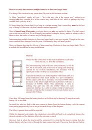
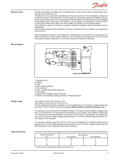
Wiring diagram<br />
-<br />
+<br />
2<br />
7<br />
3<br />
6<br />
5<br />
8<br />
4<br />
+<br />
-<br />
9<br />
-<br />
+<br />
+<br />
F<br />
D<br />
C<br />
P<br />
T<br />
1<br />
8380<br />
1: Electronic unit<br />
2: Battery<br />
3: Fuse<br />
4: Main switch (optional)<br />
5: Fan (optional)<br />
6: LED - Light Emitting Diode (optional)<br />
7: Thermostat<br />
8: Resistor for presetting speed (optional)<br />
9: Resistor for presetting battery protection voltage (optional)<br />
Voltage range<br />
12V systems: From 10.4V (9.6V) to 17V.<br />
24V systems: From 22.8V (21.3V) to 31.5V.<br />
The low voltage limits stated in brackets () can be established if a connection is made between the<br />
terminals C and P, please see also the passage Optional battery protection settings page 5.<br />
The electronic unit will calibrate to the applied voltage. This means that if the battery voltage is less<br />
than 17V, the electronic unit assumes that it is working in a 12V system. If the voltage is higher than<br />
17V, the electronic unit assumes that it is working in a 24V system. Consequently, the compressor<br />
does not run at power supply voltages between about 17V and the desired battery protection cutout<br />
voltage for 24V systems.<br />
A continuous voltage range from 9.6V to 31.5V can be established if a 220kΩ resistor (wiring<br />
diagram item 9) is connected between the terminals C and P. This wide voltage range makes the<br />
BD compressors very suitable for photovoltaic powering.<br />
Cable dimensions<br />
To ensure correct start and operating conditions, the following cable dimensions must be observed:<br />
Cable cross-section<br />
mm 2<br />
2.5<br />
4<br />
6<br />
10<br />
12V operation<br />
2.5<br />
4<br />
6<br />
10<br />
* "Length" means the distance between battery and electronic unit.<br />
Max length* m<br />
24V operation<br />
5<br />
8<br />
12<br />
20<br />
November 2001 CN.46.C6.02 3
Thermostat connection<br />
BD compressors can operate with normal mechanical type thermostats as used in refrigeration<br />
appliances, or with electronic thermostats. Always use new thermostats.<br />
The thermostat is connected between the terminals C and T of the electronic unit.<br />
The compressor current does not flow through the thermostat contacts.<br />
When the thermostat is cut out there will still be power on to the electronic unit.<br />
A system with no stand-by power consumption can be established if the thermostat (7) is replaced<br />
by a jumper between the terminals C and T, and the main switch (4) is replaced by a thermostat. In<br />
this case the full current to the compressor flows through the thermostat, which must be rated<br />
accordingly.<br />
Compressor speed<br />
R (8)<br />
Ω<br />
0<br />
277<br />
692<br />
1523<br />
Motor<br />
speed<br />
rpm<br />
2,000<br />
2,500<br />
3,000<br />
3,500<br />
Contr. circ.<br />
Current<br />
mA<br />
5<br />
4<br />
3<br />
2<br />
Without any resistor in the control circuit, the compressor will run<br />
with a fixed speed of 2,000 rpm when the thermostat is switched<br />
on.<br />
Other fixed speeds in the range between 2,000 and 3,500 rpm<br />
can be obtained when a resistor (8) is installed to adjust the current<br />
(mA) of the contol circuit, please see wiring diagram page 3.<br />
Fan connection<br />
If a fan is to be used, it must be connected to the electronic unit terminals + and F.<br />
Always use a 12V fan, also in 24V systems, as the electronic unit will automatically reduce the<br />
applied voltage to 12V for the fan.<br />
The max. load on the electronic unit is 0.5A average or 1A peak . The fan is allowed to start with a higher<br />
current for the first 2 seconds.<br />
If the fan becomes overloaded, both fan and compressor will be cut out by the overload protection.<br />
Troubleshooting<br />
To diagnose why a compressor comes to an unintended stop, it is recommended to have a Light<br />
Emitting Diode (LED) installed between the terminals + and D, please see page 3 and 4. Provided<br />
that the electronic unit is properly connected to the power supply, and the thermostat is on, the<br />
number of flashes emitted by the LED will give a hint about the reason for the interruption of the<br />
compressor operation.<br />
The motor windings can be checked for defects by measuring the resistance between the current<br />
lead-in pins. If the measured values between all 3 pins are approximately the same, the motor is<br />
most likely all right.<br />
The electronic unit is not to be repaired, it should not be opened at all.<br />
LED connection<br />
A 10mA Light Emitting Diode (LED) for compressor operation monitoring can be connected between<br />
the terminals + and D.<br />
Number<br />
of<br />
flashes<br />
5<br />
4<br />
3<br />
2<br />
Error type<br />
Thermal cut-out of electronic unit<br />
(If the refrigeration system has been too heavily<br />
loaded, or if the ambient temperature is<br />
high, the electronic unit will run too hot).<br />
Minimum motor speed error<br />
(If the refrigeration system is too heavily<br />
loaded, the motor cannot maintain minimum<br />
speed at approximately 1,850 rpm).<br />
Motor start error<br />
(The rotor is blocked or the differential pressure<br />
in the refrigeration system is too high<br />
(>5 bar)).<br />
Fan over-current cut-out<br />
(The fan loads the electronic unit with more<br />
than 1A peak<br />
).<br />
Operational errors will cause the LED to flash a<br />
number of times. The number of flashes depends<br />
on what kind of operational error was recorded.<br />
Each flash will last ¼ second.<br />
After the actual number of flashes there will be a<br />
delay with no flashes, so that the sequence for each<br />
error recording is repeated every 4 seconds.<br />
1 Battery protection cut-out<br />
(The voltage is outside the cut-out setting).<br />
4 CN.46.C6.02 November 2001
Protection systems<br />
The BD compressor protection system facilitates protection against compressor overload and start<br />
failure, fan overload and electronic unit overheating as well as destructive battery discharge.<br />
When an overload protection is activated, the compressor enters a cycle in which it makes start<br />
attempts at about 60 seconds intervals until a successfull start is achieved.<br />
Overload protections<br />
Voltage protection<br />
Battery protection<br />
The compressor overload and start protection cuts off power to the compressor if the compressor<br />
speed drops below approximately 1,850 rpm or this motor speed is not reached during the start<br />
sequence. Possible reasons for overload protection activating could be excess refrigeration system<br />
pressures during operation or lack of pressure equalizing at start.<br />
The fan overload protection stops the compressor and fan if the fan current exceeds 0.5A average or<br />
1A peak .<br />
An overheating of the electronic unit heat sink will cause the compressor to stop. Restart will occur<br />
automatically when a normal temperature has been reached.<br />
If a fan is installed, it will continue to run if the compressor stops due to overload or electronic unit<br />
overheating.<br />
If a voltage outside the specified range is applied to the electronic unit, the compressor does not<br />
start, or it stops if the voltage limit is exceeded during operation. The compressor will restart automatically<br />
about 1 minute after the supply voltage has reached the reset voltage within the range in<br />
question. If a fan is installed, it will start to operate without a delay as soon as the reset voltage is<br />
reached.<br />
To ensure sufficient battery power for proper compressor operation or to avoid permanent damage to<br />
the battery because of heavy discharge, the BD electronic unit facilitates also a battery protection.<br />
The compressor is stopped and restarted again according to the decided voltage limits measured<br />
on the + and - terminals of the electronic unit.<br />
Standard battery protection settings<br />
12V cut-out<br />
12V cut-in<br />
V<br />
V<br />
10.4<br />
11.7<br />
24V cut-out<br />
V<br />
22.8<br />
24V cut-in<br />
V<br />
24.2<br />
Other battery protection settings are optional if a connection, which includes a resistor, is established<br />
between terminals C and P, please see the wiring diagram page 3.<br />
Optional battery protection settings<br />
Resistor (R9)<br />
kΩ<br />
0<br />
1.6<br />
2.4<br />
3.6<br />
4.7<br />
6.2<br />
8.2<br />
11<br />
14<br />
18<br />
24<br />
33<br />
47<br />
82<br />
220<br />
12V cut-out<br />
V<br />
9.6<br />
9.7<br />
9.9<br />
10.0<br />
10.1<br />
10.2<br />
10.4<br />
10.5<br />
10.6<br />
10.8<br />
10.9<br />
11.0<br />
11.1<br />
11.3<br />
9.6<br />
12V cut-in<br />
V<br />
10.9<br />
11.0<br />
11.1<br />
11.3<br />
11.4<br />
11.5<br />
11.7<br />
11.8<br />
11.9<br />
12.0<br />
12.2<br />
12.3<br />
12.4<br />
12.5<br />
10.9<br />
12V max.<br />
voltage<br />
17.0<br />
17.0<br />
17.0<br />
17.0<br />
17.0<br />
17.0<br />
17.0<br />
17.0<br />
17.0<br />
17.0<br />
17.0<br />
17.0<br />
17.0<br />
17.0<br />
24V cut-out<br />
V<br />
21.3<br />
21.5<br />
21.8<br />
22.0<br />
22.3<br />
22.5<br />
22.8<br />
23.0<br />
23.3<br />
23.6<br />
23.8<br />
24.1<br />
24.3<br />
24.6<br />
24V cut-in<br />
V<br />
22.7<br />
22.9<br />
23.2<br />
23.4<br />
23.7<br />
23.9<br />
24.2<br />
24.5<br />
24.7<br />
25.0<br />
25.2<br />
25.5<br />
25.7<br />
26.0<br />
24V max.<br />
voltage<br />
31.5<br />
31.5<br />
31.5<br />
31.5<br />
31.5<br />
31.5<br />
31.5<br />
31.5<br />
31.5<br />
31.5<br />
31.5<br />
31.5<br />
31.5<br />
31.5<br />
31.5<br />
November 2001 CN.46.C6.02 5
Technical data<br />
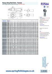
<strong>BD35F</strong><br />
General<br />
Compressor<br />
Code number: Comp. without electronic unit<br />
Code number: Electronic unit 12-24V DC,<br />
single packing<br />
<strong>BD35F</strong><br />
101Z0200<br />
101N0210<br />
Code number: Electronic unit 12-24V DC,<br />
industrial packing, 30 pcs. 101N0211<br />
Application<br />
Application<br />
LBP/MBP/(HBP)<br />
Evaporating temperature range °C -30 to 0 (10)<br />
Voltage<br />
12 - 24V DC<br />
Max. voltage 31.5V<br />
Max. machine compartment temperature °C 55<br />
Comp. cooling at ambient temp. 43°C S or F 1<br />
*<br />
Design<br />
* depending on application<br />
Displacement cm 3 2.00<br />
Oil quantity cm 3 150<br />
Maximum refrigerant charge g 300<br />
Free gas vol. in compressor housing cm 3 870<br />
Weight: Compressor/Electronic unit kg 4.3/0.25<br />
Application<br />
Blue stripe<br />
Barcode on<br />
white background<br />
Grey background<br />
S<br />
O<br />
F 1<br />
F 2<br />
<strong>BD35F</strong><br />
R134a<br />
N 1297<br />
101Z<br />
0200<br />
MADE IN GERMANY<br />
e 4<br />
0277 00<br />
EC approval mark<br />
= Static cooling normally sufficient<br />
= Oil cooling<br />
= Fan cooling 1.5 m/s<br />
(compressor compartment temperature<br />
equal to ambient temperature)<br />
= Fan cooling 3.0 m/s necessary<br />
Motor<br />
Motor type<br />
Variable Speed<br />
Resistance, all 3 windings (25°C) Ω 2.3<br />
Approvals E4 72/245 95/54 0277 00<br />
204<br />
170<br />
70<br />
100<br />
ø16<br />
D<br />
C<br />
E<br />
120<br />
B A<br />
201<br />
8269<br />
130<br />
20<br />
105<br />
78.5<br />
8369<br />
Dimensions<br />
Height mm A 137<br />
B 135<br />
B1 128<br />
B2 73<br />
127<br />
ø9<br />
Suction connector location/I.D. mm C 6.2±0.09<br />
Process connector location/I.D. mm D 6.2±0.09<br />
Discharge connector location/I.D. mm E 5.0 +0.12/+0.20<br />
B2<br />
B1<br />
Compressors on a pallet pcs. 120<br />
16<br />
46<br />
59<br />
8415<br />
28<br />
123<br />
6 CN.46.C6.02 November 2001
Performance data<br />
<strong>BD35F</strong><br />
Capacity (EN 12900/CECOMAF)<br />
rpm \ °C -30 -25 -23.3<br />
2,000 15.8 23.9 26.9<br />
2,500 20.2 29.9 33.5<br />
3,000 22.5 32.4 36.5<br />
3,500 26.2 35.9 40.4<br />
-20<br />
33.1<br />
41.2<br />
45.4<br />
50.5<br />
-15<br />
43.8<br />
54.6<br />
61.8<br />
69.8<br />
-10<br />
56.6<br />
70.7<br />
81.7<br />
93.6<br />
-5<br />
71.7<br />
89.7<br />
105<br />
122<br />
0<br />
89.9<br />
112<br />
133<br />
5<br />
111<br />
139<br />
watt<br />
10<br />
136<br />
Capacity (ASHRAE)<br />
rpm \ °C -30<br />
2,000 19.5<br />
2,500 24.9<br />
3,000 27.7<br />
3,500 32.2<br />
-25<br />
29.4<br />
36.8<br />
39.9<br />
44.2<br />
-23.3<br />
33.1<br />
41.3<br />
44.9<br />
49.7<br />
-20<br />
40.7<br />
50.7<br />
55.9<br />
62.2<br />
-15<br />
54.0<br />
67.3<br />
76.1<br />
86.0<br />
-10<br />
69.8<br />
87.1<br />
101<br />
115<br />
-5<br />
88.6<br />
111<br />
130<br />
150<br />
0<br />
111<br />
139<br />
164<br />
5<br />
137<br />
172<br />
watt<br />
10<br />
169<br />
Power consumption<br />
rpm \ °C -30<br />
2,000 17.6<br />
2,500 23.3<br />
3,000 29.9<br />
3,500 36.0<br />
-25<br />
23.4<br />
30.9<br />
36.0<br />
42.8<br />
-23.3<br />
25.3<br />
33.3<br />
38.3<br />
45.4<br />
-20<br />
28.7<br />
37.8<br />
43.0<br />
50.8<br />
-15<br />
33.6<br />
44.1<br />
50.7<br />
59.5<br />
-10<br />
38.3<br />
50.2<br />
58.7<br />
68.9<br />
-5<br />
43.0<br />
56.2<br />
66.8<br />
78.5<br />
0<br />
48.0<br />
62.3<br />
74.8<br />
5<br />
53.4<br />
68.7<br />
watt<br />
10<br />
59.5<br />
Current consumption (for 24V applications the figures must be halved)<br />
rpm \ °C -30 -25 -23.3 -20 -15 -10<br />
2,000<br />
1.5 2.0 2.1 2.4 2.8 3.2<br />
2,500<br />
1.9 2.6 2.8 3.2 3.7 4.2<br />
3,000<br />
2.5 3.0 3.2 3.6 4.2 4.9<br />
3,500<br />
3.0 3.6 3.8 4.3 5.0 5.7<br />
-5<br />
3.6<br />
4.7<br />
5.6<br />
6.5<br />
0<br />
4.0<br />
5.2<br />
6.2<br />
5<br />
4.5<br />
5.8<br />
10<br />
5.0<br />
A<br />
COP (EN 12900/CECOMAF)<br />
rpm \ °C -30 -25<br />
2,000 0.90 1.02<br />
2,500 0.87 0.97<br />
3,000 0.75 0.90<br />
3,500 0.73 0.84<br />
-23.3<br />
1.06<br />
1.01<br />
0.95<br />
0.89<br />
-20<br />
1.15<br />
1.09<br />
1.06<br />
1.00<br />
-15<br />
1.31<br />
1.24<br />
1.22<br />
1.17<br />
-10<br />
1.48<br />
1.41<br />
1.39<br />
1.36<br />
-5<br />
1.67<br />
1.60<br />
1.58<br />
1.55<br />
0<br />
1.87<br />
1.80<br />
1.78<br />
5<br />
2.08<br />
2.02<br />
W/W<br />
10<br />
2.29<br />
COP (ASHRAE)<br />
rpm \ °C<br />
2,000<br />
2,500<br />
3,000<br />
3,500<br />
-30<br />
1.10<br />
1.07<br />
0.93<br />
0.89<br />
-25<br />
1.25<br />
1.19<br />
1.11<br />
1.03<br />
-23.3<br />
1.31<br />
1.24<br />
1.17<br />
1.09<br />
-20<br />
1.42<br />
1.34<br />
1.30<br />
1.23<br />
-15<br />
1.61<br />
1.53<br />
1.50<br />
1.44<br />
-10<br />
1.82<br />
1.74<br />
1.72<br />
1.68<br />
-5<br />
2.06<br />
1.97<br />
1.95<br />
1.91<br />
0<br />
2.31<br />
2.23<br />
2.20<br />
5<br />
2.57<br />
2.50<br />
W/W<br />
10<br />
2.84<br />
Test conditions EN 12900/CECOMAF ASHRAE<br />
Condensing temperature 55°C 55°C<br />
Ambient and suction gas temp. 32°C 32°C<br />
Liquid temperature 55°C 32°C<br />
Static cooling, 12V DC<br />
1 Watt = 0.86 kcal/h<br />
November 2001 CN.46.C6.02 7