1 2 3 4 5 6 7 8 9 10 11 12 13 14 15 16 17 18 19 20 21 22 23 24 ...
1 2 3 4 5 6 7 8 9 10 11 12 13 14 15 16 17 18 19 20 21 22 23 24 ...
1 2 3 4 5 6 7 8 9 10 11 12 13 14 15 16 17 18 19 20 21 22 23 24 ...

You also want an ePaper? Increase the reach of your titles
YUMPU automatically turns print PDFs into web optimized ePapers that Google loves.
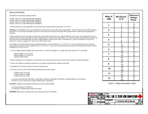
INSTALLATION NOTES<br />
Applicable for the following catalog numbers*:<br />
45-MC5 <strong>12</strong>0VX CL<strong>10</strong> 03R (CDN 2EL/3M <strong>12</strong>0/<strong>20</strong>8VX)<br />
45-MC5 <strong>12</strong>0VX CL<strong>10</strong> 06R (CDN 2EL/6M <strong>12</strong>0/<strong>20</strong>8VX)<br />
45-MC5 <strong>12</strong>0VX CL<strong>10</strong> 09R (CDN 2EL/9M <strong>12</strong>0/<strong>20</strong>8VX)<br />
45-MC5 <strong>12</strong>0VX CL<strong>10</strong> <strong>12</strong>R (CDN 2EL/<strong>12</strong>M <strong>12</strong>0/<strong>20</strong>8VX)<br />
*These instructions are also applicable when the same meter model number has the suffix: -E, -P or EP.<br />
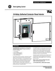
CRITICAL: The installation of the current transformer must be correct or the meter will not read properly. The load-current carrying wires must pass<br />
through the CT in the correct orientation, and the CT wires must be connected to the proper MCI screw terminals. Please see wiring diagram for<br />
reference.<br />
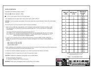
Current transformers (CTs) are used to measure the current drawn by the loads to be metered. Within the meter, the current reading from the CT is<br />
combined with the voltage readingfor the correct voltage phase to calculate the energy reading. CTs must be in phase with the reference voltage. The<br />
MCI inputs are each associated with a particular voltage phase in an A-B-C order. Input 1 is a phase A CT, input 2 is a phase B CT, input 3 is a<br />
phase C CT, input 4 is a phase A CT, and so on in A-B-C-A-B-C order.<br />
For example, a CT which measures a load supplied by phase A must be installed on CT1, CT4, CT7, etc.. Current transformers which measure a<br />
load supplied by phase B must be installed on CT2, CT5, CT8, etc.. Lastly, current transformers which measure a load supplied by phase C must be<br />
installed on CT3, CT6, CT9, etc.<br />
1. For the catalog numbers specified above, each A-B, C-A, and B-C combination is a single meter point (see Table 1 for full listing):<br />
- Meter #1 (M#1) is CT1 and CT2<br />
- Meter #2 (M#2) is CT3 and CT4<br />
- repeat for M#3 to M#<strong>12</strong><br />
2. After completing all CT terminations, connect the four (4) current connectors and then remove the the twenty-four (<strong>24</strong>) shorting links.<br />
3. Follow local codes for installation requirement, e.g. conduit, fused disconnect, distance, and wiring.<br />
4. Installation of 0.1A inputs and CL<strong>10</strong> or 5A inputs are the same.<br />
5. For three (3), six (6), and nine (9) 3-phase metering points, model numbers:<br />
- 45-MC5 <strong>12</strong>0VX CL<strong>10</strong> 03R<br />
- 45-MC5 <strong>12</strong>0VX CL<strong>10</strong> 06R<br />
- 45-MC5 <strong>12</strong>0VX CL<strong>10</strong> 09R<br />
use meter points M#1-M#3, M#1-M#6, and M#1-M#9, respectively. M#4-M#<strong>12</strong>, M#7-M#<strong>12</strong>, and M#<strong>10</strong>-M#<strong>12</strong> are not functional<br />
for three (3), six (6), and nine (9) 3-phase metering points, respectively.<br />
CAUTION: If breakers are energized, shorting links must be installed before:<br />
Meter #<br />
(M#)<br />
1<br />
2<br />
3<br />
4<br />
5<br />
6<br />
7<br />
8<br />
9<br />
<strong>10</strong><br />
<strong>11</strong><br />
<strong>12</strong><br />
MCI Board<br />
CT #<br />
1<br />
2<br />
3<br />
4<br />
5<br />
6<br />
7<br />
8<br />
9<br />
<strong>10</strong><br />
<strong>11</strong><br />
<strong>12</strong><br />
<strong>13</strong><br />
<strong>14</strong><br />
<strong>15</strong><br />
<strong>16</strong><br />
<strong>17</strong><br />
<strong>18</strong><br />
<strong>19</strong><br />
<strong>20</strong><br />
<strong>21</strong><br />
<strong>22</strong><br />
<strong>23</strong><br />
<strong>24</strong><br />
Reference<br />
Voltage<br />
Phase<br />
A<br />
B<br />
C<br />
A<br />
B<br />
C<br />
A<br />
B<br />
C<br />
A<br />
B<br />
C<br />
A<br />
B<br />
C<br />
A<br />
B<br />
C<br />
A<br />
B<br />
C<br />
A<br />
B<br />
C<br />
Table 1. Phase Association Table<br />
a) disconnecting the CT headers or<br />
b) replacing or installing meter heads on the panel.<br />
WARNING: Bodily injury or damage may result if shorting links are not installed.
WH<br />
C<br />
Neutral<br />
Load<br />
A<br />
N<br />
Phase A (ØA)<br />
Power<br />
Source<br />
Load<br />
B<br />
Phase B (ØB)<br />
Phase C (ØC)<br />
Load<br />
Reference Voltage<br />
Disconnect Method<br />
(Switch, Fuse, Circuit<br />
Breaker, etc.) --<br />
If fused,fast acting only<br />
Tenant Breaker Panel<br />
Conduit<br />
RD<br />
BK<br />
BL<br />
WH<br />
WH<br />
RD<br />
BK<br />
BL<br />
CRITICAL - Current Transformers (CT) must be<br />
installed correctly. See Diagram 1 for CT installation<br />
for each meter point. See Diagram 3 for CT polarity<br />
and Table 1 for Phase Association relationships.<br />
Meter #2 Meter #1<br />
ØA<br />
ØB<br />
RD BK BL WH<br />
ØC<br />
ØA<br />
RD BK BL WH<br />
WH<br />
RD<br />
WH<br />
BK<br />
WH<br />
BL<br />
WH<br />
RD<br />
BK<br />
WH<br />
RD<br />
BL<br />
WH<br />
RD<br />
BK<br />
BL<br />
Diagram 2. Shorting Links. See<br />
Installation Notes for details.<br />
Shorting Links<br />
BK<br />
WH<br />
RD<br />
BL<br />
MCI INTERFACE<br />
MC-5<br />
CT3 CT1<br />
CT4 CT2<br />
ØA ØB ØC N<br />
To CT1<br />
To CT3<br />
To CT2<br />
To CT4<br />
Meter #3<br />
ØB<br />
ØC<br />
RD BK BL WH<br />
WH<br />
Diagram 1. Current Transformers installed<br />
inside tenant breaker panel.<br />
BK<br />
BL<br />
Meter #6 Meter #5 Meter #4 Meter #3 Meter #2 Meter #1<br />
TENANT BREAKER PANEL<br />
WH<br />
RD<br />
WH<br />
BK<br />
WH<br />
BL<br />
WH<br />
RD<br />
WH<br />
BK<br />
WH<br />
BL<br />
WH<br />
RD<br />
WH<br />
BK<br />
WH<br />
BL<br />
WH<br />
RD<br />
WH<br />
BK<br />
WH<br />
BL<br />
WH<br />
RD<br />
WH<br />
BK<br />
WH<br />
BL<br />
WH<br />
RD<br />
WH<br />
BK<br />
WH<br />
BL<br />
WH<br />
RD<br />
WH<br />
BK<br />
WH<br />
BL<br />
WH<br />
RD<br />
WH<br />
BK<br />
WH<br />
BL<br />
TENANT BREAKER PANEL<br />
Meter #<strong>12</strong> Meter #<strong>11</strong> Meter #<strong>10</strong> Meter #9 Meter #8 Meter #7<br />
LOAD<br />
LOAD<br />
X1 (WHITE)<br />
X2 (RD/BK/BL)<br />
LINE SOURCE<br />
Dot<br />
H1<br />
Diagram 3. CT Phasing.<br />
Dot or H1 should point<br />
towards the line or<br />
source.<br />
343<br />
51<br />
737<br />
Diagram 4. Typical box<br />
orientation and<br />
dimensions (in cm).<br />
LOAD<br />
2<strong>16</strong><br />
483
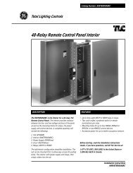
BEFORE READING THE DISPLAY FOR ANY MC5 PRODUCT<br />
CAUTION: When reading the meter display, all consumption and demand values must be multiplied by the correct<br />
multiplier to calculate true value. This includes all register values (kWh, kW, kVARHLg, kVARHLd, etc.) and Phase<br />
Diagnostic values (real time Amps, Watts, etc.).<br />
Volts, phase angle, frequency and power factor are displayed on the LCD as their true values and should not be<br />
multiplied.<br />
Meter<br />
Voltage<br />
Ratings<br />
FOR<br />
CT Rating<br />
<strong>20</strong>0A<br />
400A<br />
600A<br />
Multiplier for<br />
5.0A CT<br />
x40.0<br />
x80.0<br />
x<strong>12</strong>0.0<br />
The multiplier value is dependent upon the ratio of the external Current Transformers (CTs) and can be different for<br />
different meter points. Please consult Table 1 CT Multipliers for the appropriate value dependent upon the rating (or<br />
size) of the CT.<br />
HOW CT MULTIPLIERS ARE CALCULATED:<br />
0.1AMP CTs<br />
The multiplier values for CTs with 0.1A secondary ratings are derived by dividing the primary side rating by <strong>10</strong>0. For<br />
example, a 50:0.1A-rated CT will have a multiplier of 50 ÷ <strong>10</strong>0, which is 0.50. A <strong>10</strong>0:0.1A rated CT will have a<br />
multiplier of <strong>10</strong>0 ÷ <strong>10</strong>0 which is 1.)<br />
<strong>12</strong>0V,<br />
<strong>20</strong>8V,<br />
277V,<br />
347V,<br />
480V,<br />
600V<br />
800A<br />
<strong>12</strong>00A<br />
<strong>15</strong>00A<br />
<strong>16</strong>00A<br />
<strong>20</strong>00A<br />
3000A<br />
x<strong>16</strong>0.0<br />
x<strong>24</strong>0.0<br />
x300.0<br />
x3<strong>20</strong>.0<br />
x400.0<br />
x600.0<br />
5AMP CTs<br />
For CTs with 5A secondary ratings, the multipliers are derived by dividing the primary side rating by 5. For example,<br />
a <strong>20</strong>0:5A-rated CT will have a multiplier of <strong>20</strong>0 ÷ 5, which is 40.<br />
3<strong>20</strong>0A<br />
4000A<br />
x640.0<br />
x800.0<br />
EXAMPLE:<br />
Meter point with 400:0.1A CT<br />
LCD reading for meter is 34<strong>22</strong>.<strong>11</strong>9kWh<br />
The correct cumulative consumption (kWh) for this meter is <strong>13</strong>688.476 kWh.<br />
(400 ÷ <strong>10</strong>0 = 4. Multiply face value for consumption and demand values by 4. 34<strong>22</strong>.<strong>11</strong>9 x 4 =<strong>13</strong>688.476)<br />
NOTE: Failure to use the appropriate multiplier will result in an incorrect diagnosis of the meter's<br />
functionality and incorrect revenue billing.<br />
FOR<br />
<strong>24</strong>0V<br />
<strong>10</strong>0A<br />
<strong>20</strong>0A<br />
x<strong>20</strong>.0<br />
x40.0<br />
Note: Contact Quadlogic for 0.1A<br />
CT multipliers.<br />
Table 1. CT Multipliers