Instruction manual - Maddalena
Instruction manual - Maddalena
Instruction manual - Maddalena

Create successful ePaper yourself
Turn your PDF publications into a flip-book with our unique Google optimized e-Paper software.
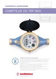
1. Application and function<br />
This compact heat meter microCLIMA U is designed for<br />
measurement of the consumed heat energy in a closed<br />
heating system.<br />
2. Content of the Package<br />
<br />
<br />
<br />
Heat meter, consisting of a detachable calculator,<br />
flow sensor and two temperature sensors, all<br />
permanently connected to each other.<br />
Installation kit<br />
Installation and Operating <strong>Instruction</strong>s<br />
3. General Information<br />
<br />
<br />
<br />
<br />
<br />
<br />
<br />
<br />
<br />
<br />
<br />
<br />
<br />
microCLIMA U<br />
Ultrasonic Compact Heat Meter<br />
DE-13-MI004-PTB001<br />
Installation and Operating <strong>Instruction</strong>s<br />
The valid standards for the application of heat<br />
meters are EN 1434, parts 1 + 6, Council Directive<br />
on EMC 2004/22/EC, annex I and MI-004 and the<br />
relevant national verification regulations.<br />
The regulations for electrical installations are to be<br />
observed.<br />
The product meets the requirements relating to<br />
emissions in the European Council Directive<br />
EMC 2004/108/EC.<br />
The measurement stability of the heat meters is only<br />
guaranteed when the quality of the water meets the<br />
conditions as specified in the AGFW<br />
Recommendation FW-510.<br />
The identification plate of the instrument and the<br />
seals must not be removed or damaged – otherwise<br />
the guarantee and the approved application of the<br />
instrument are no longer valid!<br />
The heat meter left the factory in conformance with<br />
all applicable safety regulations. All maintenance<br />
and repair work is to be carried out only by qualified<br />
and authorized technical personnel.<br />
The direct-mounted temperature sensor and/or the<br />
external temperature sensor installation point may<br />
not be altered in any way, in particular the sealing<br />
wire must not be removed.<br />
The instrument must be stored and transported at<br />
temperatures above-freezing.<br />
To protect against damage and dirt the heat meter<br />
should only be removed from the packaging directly<br />
before installation.<br />
Instruments with a return-flow temperature sensor<br />
mounted directly in the flow sensor may only be<br />
mounted in the return flow.<br />
All details and specifications listed on the data sheet<br />
of the heat meter must be adhered to.<br />
All electrical connections must be laid at a minimum<br />
distance of 10 cm to sources of electromagnetic<br />
<br />
<br />
<br />
<br />
<br />
interference (switches, controllers, pumps, etc.). All<br />
instrument connections must be laid at a minimum<br />
distance of 5 cm to other current-carrying wires.<br />
The temperature sensor cables must not be kinked,<br />
rolled up, lengthened or shortened.<br />
To clean the heat meter (only if necessary) use a<br />
slightly moist cloth.<br />
Categorically, all temperature sensors which are not<br />
mounted in the flow sensor must be direct-mounted.<br />
If more than one heat meter is installed in one unit,<br />
care must be taken to ensure that all the meters<br />
have the same installation conditions.<br />
Pay attention to the installation point of the heat<br />
meter:<br />
standard: in the return flow pipe<br />
optional: in the forward flow pipe (must be<br />
specifically requested when ordering).<br />
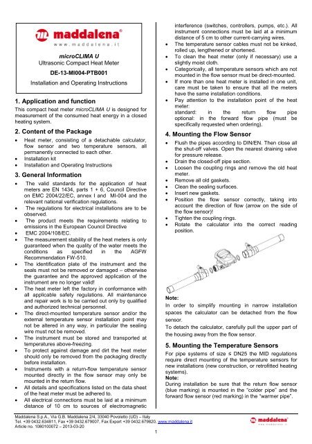
4. Mounting the Flow Sensor<br />
<br />
<br />
<br />
<br />
<br />
<br />
<br />
<br />
<br />
Flush the pipes according to DIN/EN. Then close all<br />
the shut-off valves. Open the nearest draining valve<br />
for pressure release.<br />
Drain the closed-off pipe section.<br />
Loosen the coupling rings and remove the old heat<br />
meter.<br />
Remove all old gaskets.<br />
Clean the sealing surfaces.<br />
Insert new gaskets.<br />
Position the flow sensor correctly, taking into<br />
account the direction of flow (arrow on the side of<br />
the flow sensor)!<br />
Tighten the coupling rings.<br />
Rotate the calculator into the correct reading<br />
position.<br />
Note:<br />
In order to simplify mounting in narrow installation<br />
spaces the calculator can be detached from the flow<br />
sensor.<br />
To detach the calculator, carefully pull the upper part of<br />
the housing away from the flow sensor.<br />
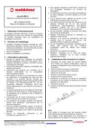
5. Mounting the Temperature Sensors<br />
For pipe systems of size ≤ DN25 the MID regulations<br />
require direct mounting of the temperature sensors for<br />
new installations (new construction, or retrofitted heating<br />
systems).<br />
Note:<br />
During installation be sure that the return flow sensor<br />
(blue marking) is mounted in the “colder pipe” and the<br />
forward flow sensor (red marking) in the “warmer pipe”.<br />
<strong>Maddalena</strong> S.p.A., Via G.B. <strong>Maddalena</strong> 2/4, 33040 Povoletto (UD) – Italy<br />
Tel. +39 0432.634811, Fax +39 0432.679007, Fax Export +39 0432.679820, www.maddalena.it<br />
Article no. 1080100072 – 2013-03-20<br />
1
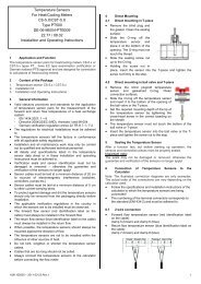
5.1. Direct mounting (ball valve and T-piece)<br />
<br />
<br />
<br />
<br />
<br />
Remove the blind plug/old temperature sensor and<br />
gasket/old O-ring. Clean connection<br />
surfaces.<br />
Slide the O-ring off the temperature<br />
sensor and insert it to the bottom of<br />
the threaded opening of the ball valve<br />
or the T-piece.<br />
Set the required mounting depth of<br />
the tip of the temperature sensor by<br />
tightening the cross-head screw in<br />
the correct beading on the sheath.<br />
The temperature sensor must not<br />
touch the bottom of the ball valve or<br />
T-piece.<br />
Insert the temperature sensor into the ball valve or<br />
the T-piece and tighten the screw nut to the stop.<br />
6. Start of Operation<br />
Slowly open the shut-off valves<br />
Check that the meter is functioning properly and that<br />
there are no leaks.<br />
After confirming that the heat meter is the<br />
functioning properly, apply the seals for the<br />
temperature sensors and the flow sensor.<br />
When replacing a meter at the end of a verification<br />
period note the meter readings and the serial<br />
numbers of the old and new meters.<br />
Check the following points:<br />
<br />
<br />
<br />
<br />
<br />
<br />
<br />
<br />
Is the heat meter of the right size?<br />
Are the shut-off valves open?<br />
Is the heating system clear (dirt filters not clogged?)<br />
Are the temperature sensors and the flow sensor<br />
sealed (against manipulation)?<br />
Is the directional arrow on the flow sensor in line<br />
with the flow direction?<br />
Is a flow volume displayed?<br />
Is a plausible temperature difference displayed?<br />
For instruments with an integrated return flow<br />
temperature sensor, check, if the flow sensor is<br />
installed in the return flow.<br />
7. Technical data<br />
Data Approval q p 2,5 q p 3,5<br />
Accuracy class<br />
EN 1434-1:2007,<br />
class 2 / 3<br />
Minimal flow q i/q p 1:100<br />
EN 1434-<br />
1:2007,<br />
class 2 / 3<br />
1:100<br />
1:125<br />
1:150<br />
Maximum flow q s/q p 2:1 2:1<br />
Mechanical class M1 M1<br />
Electromagnetic class E1 E1<br />
Protection class IP54 IP54<br />
Flow disturbance class U0 U0<br />
<strong>Maddalena</strong> S.p.A., Via G.B. <strong>Maddalena</strong> 2/4, 33040 Povoletto (UD) – Italy<br />
Tel. +39 0432.634811, Fax +39 0432.679007, Fax Export +39 0432.679820, www.maddalena.it<br />
Article no. 1080100072 – 2013-03-20<br />
2<br />
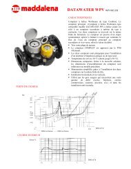
Details Flow Sensor S2U<br />
Nominal diameter DN mm 20 20 25<br />
DNDNDNNennweite<br />
Nominal flow q<br />
DN<br />
p m³/h 2.5 3.5 3.5<br />
Max. flow q s m³/h 5.0 7.0 7.0<br />
Pressure drop ∆p at q p mbar 115 210 210<br />
Nominal pressure PN bar 16<br />
Maximum pressure MAP<br />
bar<br />
Low flow threshold l/h 12<br />
Installation length mm 130 130 150<br />
External connection<br />
thread<br />
16<br />
Zoll G1B G1B G1¼B<br />
Temp. range of medium °C 15 ... 90<br />
Mounting position<br />
Point of installation<br />
standard<br />
optional<br />
Technical Data Calculator<br />
horizontal; vertical<br />
return flow<br />
forward flow<br />
Ambient temperature °C 5 ... 55<br />
Temperature range °C 1 ... 150<br />
Temperatur difference K 3 ... 100<br />
Power supply<br />
Lifetime of battery<br />
Data storage<br />
Display<br />
Interfaces<br />
standard<br />
optional<br />
Details Temperature Sensors<br />
PT1000<br />
Connection<br />
3V, lithium<br />
6 + 1 year<br />
E 2 PROM / daily<br />
8-digits + special<br />
characters<br />
infrared<br />
M-Bus<br />
platinium precision<br />
2 wire resistor technique<br />
Diameter mm 5.0 or 5.2<br />
Length of connecting cables m 1.5<br />
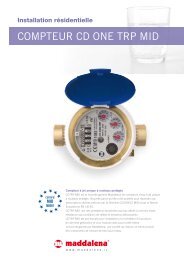
8. Display<br />
The calculator has a liquid crystal display with 8 digits<br />
and special characters. The values that can be shown<br />
are divided into three display loops. All data can be<br />
retrieved via the key.<br />
In standard mode (no push-button action), the<br />
information displayed is the total heat energy consumed<br />
since the meter was put into operation.<br />
At the start you are automatically in the main loop (1st<br />
level). By pressing the push-button longer than<br />
4 seconds you change to the next display loop. Keep the<br />
push-button pressed until you reach the desired<br />
information loop.
By pressing the push-button briefly you can scan all the<br />
information within a loop.<br />
After 1 minute of non-use of the push-button, the display<br />
automatically returns to the main loop.<br />
1. Level / Main Loop<br />
5) Temperature difference<br />
6) Days in operation since verification<br />
7) Sensor type / installation Position<br />
1) Total heat energy in MWh – standard display- alternating display<br />
without pressing at negative flow.<br />
8) M-bus address<br />
2) Segment test, all segments triggered simultaneously.<br />
9) Serial number of the heat meter<br />
3) Heat energy at last billing date alternating with last billing date 1)<br />
10) Firmware / software version<br />
3. Level: Statistics Loop<br />
4) Total volume in m³<br />
5) Current power in kW<br />
1.) Previous billing date alternating with its value. Alternatively, the total<br />
volume, tariff values, or values of individual instruments connected to<br />
the optional pulse inputs can be displayed, if so set. 1)<br />
6) Current flow in m³/h<br />
2..-16.) Monthly values: Dates alternating with their value. Alternatively,<br />
the total volume, tariff values, or the values of individual pulse counters<br />
can be displayed, if so set 1)<br />
7) Current date<br />
1) Up to the end of the month the consumption and reading date for that<br />
month will be shown as 0.<br />
8) Error message (alternating binary and hexadecimal display)<br />
2. Level / Technician’s Loop<br />
1) Maximum power in kW<br />
2) Maximum flow in m³/h<br />
9. Interfaces and Options<br />
9.1. Optical (infrared) interface<br />
In order for a PC to be able to communicate with a<br />
SensoStar 2U® instrument, it is necessary to connect an<br />
USB interface of the PC. The optocoupler and the<br />
necessary software „Device®Monitor“ are optionally<br />
available.<br />
Baudrate (2400 Bd)<br />
The optical infrared interface is activated with the key. If<br />
within 60 seconds neither a valid telegram is received<br />
nor the push-button pressed again, the interface is<br />
deactivated.<br />
9.2. M-Bus<br />
3) Forward flow temperature in °C<br />
With the optional M-Bus the protective interface is<br />
galvanically separated. In a maximum-sized M-Bus<br />
network of 250 meters, 24 read-outs per day are<br />
possible for each meter. If fewer read-outs are carried<br />
4) Return flow temperature in °C<br />
out and/or fewer heat meters are installed in the network<br />
(connected to the M-Bus system), the unused amount of<br />
available read-outs is stored in the instrument to be used<br />
when needed.<br />
<strong>Maddalena</strong> S.p.A., Via G.B. <strong>Maddalena</strong> 2/4, 33040 Povoletto (UD) – Italy<br />
Tel. +39 0432.634811, Fax +39 0432.679007, Fax Export +39 0432.679820, www.maddalena.it<br />
Article no. 1080100072 – 2013-03-20<br />
3
Low Battery<br />
Check sum fault<br />
E 2 PROM fault<br />
Reset<br />
Time-out TDC<br />
REF-Sensor fault<br />
RF sensor fault<br />
VF sensor fault<br />
9.2.1. General information<br />
<br />
<br />
<br />
<br />
<br />
<br />
<br />
<br />
<br />
The number of read-outs via the optical interface is<br />
limited.<br />
During communication on the M-Bus with an<br />
addressed instrument via the M-Bus it is not<br />
possible to use the other interfaces on the<br />
instrument (push-button, optical interface) and vice<br />
versa.<br />
The valid standards for the M-Bus protocol are<br />
EN 13757-2, EN 13757-3 and EN 1434-3 and the M-<br />
Bus Recommendation (version 4.8 from Nov. 1997)<br />
with the basic standard IEC 870 parts 1,2 and 4.<br />
Each meter on the M-Bus is only protected against<br />
high voltage up to the maximal allowed bus voltage<br />
(±50V).<br />
Additional protective measures must be provided by<br />
the level converter/Master.<br />
The installation of an instrument in a M-Bus network<br />
may only be carried out by authorized, qualified<br />
technical personnel.<br />
Attention must be paid to ensure that the cable<br />
lengths and cable cross-sections in the bus network<br />
are appropriate for the baud rate of the connected<br />
meters (2400 baud).<br />
Recommended cable type:<br />
Telephone cable J-Y(ST) Y2 x 2 x 0.8 mm²<br />
10. Error Codes<br />
When the instrument detects an error, the<br />
error symbol and number are displayed.<br />
The error can also be displayed by selecting<br />
the menu item 8) ‘error display’ in the first level / main<br />
loop (see loop 8 display).<br />
There are seven possible causes of error, and they can<br />
appear in combination with each other, depending on<br />
the situation. The description of the faults can be read<br />
from the display.<br />
Error<br />
Error<br />
code<br />
7 6 5 4 3 2 1 0<br />
Display 1 2 3 4 5 6 7 8<br />
Location<br />
Binary<br />
display<br />
LCD<br />
Error code<br />
hexadecimal<br />
(LDC)<br />
When an error occurs in the standard display (total<br />
heat energy), with the exception of the „reset“ error, the<br />
instrument must be exchanged and sent to the<br />
manufacturer for examination.<br />
Error Description<br />
Error Effect Possible cause<br />
ff-sensor<br />
fault<br />
rf-sensor<br />
fault<br />
No calculations are carried<br />
out. The registers for flow<br />
and energy are not being<br />
updated (no new data is<br />
being stored).<br />
No calculations are carried<br />
out. The registers for flow<br />
and energy are not being<br />
updated (no new data is<br />
being stored).<br />
Sensor cable severed;<br />
sensor cable shorted<br />
circuited.<br />
Sensor cable severed;<br />
sensor cable shorted<br />
circuited t.<br />
Display<br />
binary<br />
Description<br />
1 at 1st position check sum fault error 40<br />
Display<br />
hexadecimal<br />
Internal<br />
calibration<br />
errors<br />
There is no energy<br />
calculation. The registers for<br />
flow and energy are not<br />
being updated (no new data<br />
is being stored).<br />
A defect on the calculator<br />
circuit board.<br />
1 at 2nd position E 2 PROM fault error 20<br />
1 at 3rd position Reset error 10<br />
1 at 4th position Time-out TDC error 08<br />
Time-out<br />
TDC<br />
No calculations are carried<br />
out. The registers for flow<br />
and energy are not being<br />
updated (no new data is<br />
being stored).<br />
1. No water in flow sensor<br />
2. Air in medium<br />
3. Transducer/cable defect<br />
1 at 5th position REF-sensor fault error 04<br />
1 at 6th position RF-sensor fault error 02<br />
1 at 7th position FF-sensor fault error 01<br />
reset<br />
E 2 PROM<br />
fault<br />
The measurements since<br />
the last storage of data in<br />
the E 2 PROM are lost (max.<br />
one day)<br />
After a reset, the instrument<br />
is without function.<br />
EMC<br />
Defective component.<br />
Example: Time-out<br />
check<br />
sum fault<br />
No calculations are carried<br />
out. The registers of flow<br />
and energy are not being<br />
updated.<br />
Defective component.<br />
<strong>Maddalena</strong> S.p.A., Via G.B. <strong>Maddalena</strong> 2/4, 33040 Povoletto (UD) – Italy<br />
Tel. +39 0432.634811, Fax +39 0432.679007, Fax Export +39 0432.679820, www.maddalena.it<br />
Article no. 1080100072 – 2013-03-20<br />
4
11. Mounting with wall support<br />
There is a wall mounting support and a sticker pad<br />
available, which must be ordered separately.<br />
12. Declaration of Conformity<br />
For the product described in this document we confirm, as<br />
the manufacturer, that it meets the fundamental<br />
requirements according to the<br />
<br />
<br />
Council Directive 2004/22/EC of 31 March 2004 on<br />
the approximation of the laws of the member states<br />
relating to measurement instruments, in particular<br />
those in annex MI-004, as well as<br />
the requirements relating to emissions in the<br />
European Council Directive on EMC 2004/108/EC,<br />
and the requirements according to the Council Low<br />
Voltage Directive 2006/95/EC.<br />
The complete signed declaration can be found at<br />
www.engelmann.de.<br />
13. Contacts<br />
<strong>Maddalena</strong> S.p.A.<br />
Via G.B. <strong>Maddalena</strong>, 2/4<br />
33040 Povoletto (UD) – Italy<br />
Tel.: +39.0432.634811<br />
Fax.: +39.0432.679820<br />
www.maddalena.it<br />
Subject to technical change withour prior notice<br />
<strong>Maddalena</strong> S.p.A., Via G.B. <strong>Maddalena</strong> 2/4, 33040 Povoletto (UD) – Italy<br />
Tel. +39 0432.634811, Fax +39 0432.679007, Fax Export +39 0432.679820, www.maddalena.it<br />
Article no. 1080100072 – 2013-03-20<br />
5