Gulf of Mexico mid-year report: - Weatherford International
Gulf of Mexico mid-year report: - Weatherford International
Gulf of Mexico mid-year report: - Weatherford International

Create successful ePaper yourself
Turn your PDF publications into a flip-book with our unique Google optimized e-Paper software.
Houston London Paris Stavanger Aberdeen Singapore Moscow Baku Perth Rio de Janeiro Lagos Luanda<br />
For continuous news & analysis<br />
www.<strong>of</strong>fshore-mag.com<br />
World Trends and Technology for Offshore Oil and Gas Operations<br />
June 2011<br />
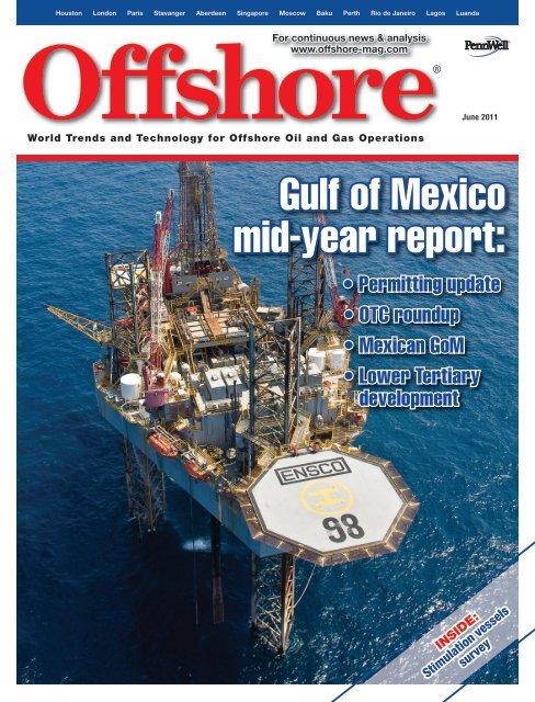
<strong>Gulf</strong> <strong>of</strong> <strong>Mexico</strong><br />
<strong>mid</strong>-<strong>year</strong> <strong>report</strong>:<br />
• Permitting update<br />
• OTC roundup<br />
• Mexican GoM<br />
• Lower Tertiary<br />
development<br />
INSIDE:<br />
Stimulation vessels<br />
survey
D R I L L I N G & C O M P L E T I O N<br />
Liner drilling technology<br />
reduces non-productive time<br />
Complex drilling challenges <strong>of</strong>ten require unconventional solutions<br />
such as liner drilling to reach a successful outcome<br />
Steven M. Rosenberg<br />
Deepak M. Gala<br />
<strong>Weatherford</strong> <strong>International</strong> Ltd.<br />
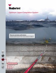
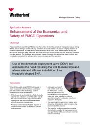
Hydraulic liner hanger<br />
system components.<br />
It is a well-established reality that the world’s growing appetite<br />
for oil and gas is increasingly being fed from remote, deepwater<br />
fields and technically complex reservoirs. To mitigate the significant<br />
drilling challenges and operational risks that inevitably<br />
come with these locales, drilling engineers have to look beyond<br />
their conventional drilling techniques and consider novel well construction<br />
technologies.<br />
In a relatively short time, liner drilling (LD) has proven itself as<br />
a reliable technology for addressing a host <strong>of</strong> drilling hazards in<br />
harsh environments, including lost circulation, depletion, wellbore<br />
stability, getting liner to bottom, and wellbore ballooning issues. LD<br />
<strong>of</strong>fers several important benefits that help ensure the liner is set to<br />
its target depth:<br />
• The technology creates a so-called “smear effect” in which the<br />
close proximity <strong>of</strong> the liner wall to the borehole smears cuttings<br />
against the formation, creating an impermeable wall cake and<br />
minimizing lost circulation<br />
• This close proximity also results in considerably higher annular<br />
velocities for a given circulation rate compared to conventional<br />
drilling, which leads to better hole cleaning while drilling<br />
• LD can require little or no hole preparation. The liner can be<br />
landed and cemented almost immediately upon reaching target<br />
depth with minimal delay for cementing operations<br />
• LD helps reduce the rate <strong>of</strong> fluid loss in the annulus compared<br />
to conventional drilling operations, enabling annular fluid loss<br />
to be managed with a rig’s trip tank pump<br />
• The rigidity <strong>of</strong> the liner being used acts as a stiff BHA, enabling<br />
maintenance <strong>of</strong> existing hole inclination and azimuth within the<br />
constraints <strong>of</strong> the well’s directional requirements<br />
• Trip margin is eliminated, as there is no need for the liner to be<br />
pulled out <strong>of</strong> the hole<br />
• No rig modifications are required; the same surface equipment<br />
used for conventional liner running operations is used for LD<br />
• LD is used when required to mitigate a particular well challenge,<br />
allowing well construction to continue and minimizing<br />
NPT in the process.<br />
These benefits have helped several <strong>Gulf</strong> <strong>of</strong> <strong>Mexico</strong> (GoM) operators<br />
achieve their drilling objectives, as the case histories below<br />
demonstrate.<br />
Drilling through depleted sand<br />
A deepwater GoM operator selected LD to drill through and isolate<br />
a pressured shale and depleted sand in a single-hole section.<br />
Conventional methods would require two strings <strong>of</strong> casing, which<br />
was unacceptable due to severe slimming <strong>of</strong> the wellbore.<br />
Equipment Selection. A review <strong>of</strong> existing bit records and lithology<br />
information indicated that a three-bladed, 7 5 ⁄8-in. × 8 1 ⁄2-in. CWD<br />
bit with a thermally stable polycrystalline (TSP) diamond cutting<br />
Reprinted with revisions to format, from the June 2011 edition <strong>of</strong> OFFSHORE<br />
Copyright 2011 by PennWell Corporation
D R I L L I N G & C O M P L E T I O N<br />
structure would be best for this application. The CWD bit had 6-mmround<br />
TSP diamond cutters pressed into aluminum blades containing<br />
high-velocity oxy fuel (HVOF) hardfacing, and a tungsten carbide<br />
gauge section to enable back-reaming. The bit was fitted with<br />
drillable and interchangeable copper nozzles to minimize damage to<br />
the subsequent shoe-track drill-out bit. The aluminum nose and cutting<br />
structure were fully drillable with conventional PDC or rollercone<br />
bits, eliminating a costly drill-out trip.<br />
A 4,260-ft, 7 5 ⁄8-in., 39-lb/ft Q-125 HYD-523 hydraulically set liner<br />
system was selected, which was designed for extended rotation periods<br />
in deep, high-angle applications and to allow for maximum workability<br />
during deployment.<br />
The key for success with hydraulic liner systems is safe management<br />
<strong>of</strong> the circulating pressures. The premium liner is equipped<br />
with special mechanical locking devices, which are deactivated<br />
when the hydraulic setting pressure is reached. These devices prevent<br />
premature setting while running in the hole (RIH) and allow for<br />
the highest flow rates and pressures to be used, further aiding the<br />
workability <strong>of</strong> the system.<br />
The hanger is set by applying hydraulic pressure to shear the<br />
pins in the cylinder, which forces the connector ring and slips up the<br />
cone and into the host casing; the liner’s weight is then transferred<br />
to the slips by lowering the running string.<br />
The setting tool is used to rotate the liner when running in the<br />
well and during the LD operation. Hydraulic pressure, coupled with<br />
a ball-dropping event, shears the sleeve <strong>of</strong> the hydraulic cylinder on<br />
the setting tool so that it can be mechanically released. Drill pipe<br />
weight is slacked <strong>of</strong>f to de-clutch the tool, which is then turned<br />
to the right to release the float nut. Hydraulic pressure is then reapplied<br />
to shear the ball from its seat in the liner wiper plug tool,<br />
thereby restoring circulation. The running string is then picked up<br />
to check that the setting tool is free, which is confirmed by the loss<br />
<strong>of</strong> the liner weight.<br />
The packing element is designed to trap atmospheric pressure<br />
underneath it. Thus, as the liner system is lowered into the wellbore,<br />
hydrostatic pressure acts to vacuum it to the liner-top packer<br />
mandrel. This capability helps improve packer performance by preventing<br />
swabbing, premature setting and cuttings accumulation underneath<br />
the packing element.<br />
The packer is set by raising the running string to expose the<br />
packer actuator, forming a no-go which is set down on the polishedbore<br />
receptacle (PBR). The no-go transfers weight through the<br />
PBR, shearing the pins in the packer and allowing the element and<br />
slips to be set in the host casing and the ratchet rings to lock in<br />
the compressive forces. A tieback completion PBR using a patented<br />
locking mechanism helps prevent the PBR from backing <strong>of</strong>f when<br />
tight dogleg sections or high-debris environments are encountered.<br />
LD operation. For the first section, the CWD bit and hydraulic<br />
liner hanger system were used to ream and drill the 7 5 ⁄8-in. liner a<br />
distance <strong>of</strong> 107 ft through the pressured shale and depleted sand.<br />
Existing 9 7 ⁄8-in. casing was set at 16,156 ft (4,924 m) MD with 60<br />
degrees <strong>of</strong> inclination. The existing 8 1 ⁄2-in. × 9 7 ⁄8-in. hole was 20,419<br />
ft measured depth (MD). The 4,260 ft (1,299 m) liner was washed<br />
and reamed from 20,320 ft (6,194 m) to 20,419 ft (6,223.7 m) MD and<br />
drilled in an additional 8 ft to 20,427 ft (6,226 m) MD.<br />
The next hole section in the same well contained a 13.5-ppge pressured<br />
shale overlying the 7.7-ppge depleted pay sand. After drilling a<br />
6 1 ⁄2-in. × 7 1 ⁄2-in. bi-center hole through the depleted pay sand, a 5 1 ⁄2-in.,<br />
23-lb/ft, Q-125, HYD-513 liner was reamed in using a 5 1 ⁄2-in. × 6 1 ⁄2-in.<br />
CWD bit. No mud losses were recorded while the 328-ft liner was<br />
reamed from 20,427 ft (6,226 m) to 20,519 ft (6,254 m) MD in the<br />
existing 6 1 ⁄2-in. × 7 1 ⁄2-in. hole. The LD system allowed the operator to<br />
successfully case <strong>of</strong>f the depleted 92-ft (28 m) pay sand interval with<br />
no fluid losses, saving time and cost over conventional methods that<br />
had a low chance <strong>of</strong> success.<br />
Casing challenges<br />
A GoM shelf operator decided to case <strong>of</strong>f an unstable shale section<br />
and a severely depleted 2-ppge sand with a 480-ft (146.3 m), 5½ -in.<br />
23-lb/ft Q-125, HYD-513 liner at a wellbore inclination <strong>of</strong> 38°. A threebladed,<br />
PDC drillable 5½-in. x 6½-in. CWD bit with TSP diamond<br />
cutting structure was selected for the LD operation. The operator required<br />
a 3½ -in. production tubing to ensure economic success, which<br />
necessitated a minimum 4½ -in. hole size to total depth after drilling<br />
out the 5½ -in. liner.<br />
As part <strong>of</strong> the rotary string, the liner string would be subjected to<br />
typical borehole drilling forces and dynamics. Therefore, the 5½ -in.<br />
liner running/drilling tool system was specifically engineered with<br />
up to 38,000 pound force/feet (lbf/ft) <strong>of</strong> drilling torque capability.<br />
The tool’s release was controlled by hydraulic differential pressure<br />
across an internal ball seat in the setting tool, rather than between<br />
the inside diameter (ID) and outside diameter (OD) <strong>of</strong> the tool,<br />
which is the setting method common to conventional liner hangers<br />
and running/setting tools.<br />
Liner reaming and drilling. During reaming, shale pack-<strong>of</strong>f was<br />
experienced in the previously drilled shale intervals, requiring operator<br />
and service company teamwork to work the pipe through the<br />
shale intervals. In the second shale section from 13,759 ft (4,193.7<br />
m) to 13,779 ft (4,199.8 m), as much as 55,000 lb <strong>of</strong> over pull was required<br />
to work the liner free. Pump pressure had increased to 1,686<br />
psi, with surface torque measured as high as18,000 lbf/ft; however,<br />
no fluid was lost to the formation during the reaming operation.<br />
The drilling operation required 10 hours to drill 19 ft <strong>of</strong> new hole<br />
(from 13,779 (4,199.8 m) to 13,798 ft (4,205.6 m) MD). Rotary speed<br />
ranged from 26 to 50 rpm, weight on bit (WOB) from 0 to 13,000<br />
lb, and drilling torque from 8,000 to 9,000 lbf/ft. A 12.1 ppg WBM<br />
was used. After cementing the liner in place, an 18.3-ppge formation<br />
integrity test (FIT) verified that the 4½-in. hole required for the<br />
completion could be achieved. As in the reaming phase, no fluid was<br />
lost to the formation. No comparison how much fluid was lost on<br />
<strong>of</strong>fset wells is available as this was one-<strong>of</strong>f well.<br />
Catastrophic thief zone<br />
A GoM operator selected LD to case <strong>of</strong>f a catastrophic thief zone,<br />
which was not possible using conventional drilling methods. Planning<br />
for the LD operation had to be completed within a 48-hr window<br />
to avoid rig downtime.<br />
A three-bladed 9 5 ⁄8-in. x 12 1/4-in. CWD bit with TSP diamond cutting<br />
structure was selected, as was the premium 9 5 ⁄8-in., 53.5-lb/ft,<br />
HCP-110, SLIJ-II hydraulic liner hanger system highlighted in the<br />
first case study. A 13.4-ppg water-based mud (WBM) was used for<br />
the LD operation.<br />
After the liner was successfully run to 7,069 ft (2,154 m) MD, the<br />
existing 12¼-in. hole was washed and reamed from 7,069 ft to 7,164<br />
ft (2,183.5 m), at a rotary speed <strong>of</strong> 40 rpm, torque between 2,500 and<br />
3,500 lbf/ft, surface pump pressure <strong>of</strong> 1,100 psi and a circulation rate<br />
<strong>of</strong> 500 gpm. Hook load readings verified that the open hole was in<br />
good condition. Liner washing and reaming continued to the bottom<br />
<strong>of</strong> the 12¼-in. section, at 7,367 ft (2,245 m) MD.<br />
The liner was then drilled into a sand and shale sequence from<br />
7,367 ft to 7,636 ft at an average rate <strong>of</strong> penetration (ROP) <strong>of</strong> 7.7 ft/<br />
hr and an on-bottom rotating time <strong>of</strong> 35 hr. There were no <strong>report</strong>ed<br />
mud losses to the formation while LD and cementing the 9 5 ⁄8-in. casing.<br />
The liner hanger set without incident and the liner-setting tool<br />
was released and retrieved without problem.<br />
Eliminate contingency liner<br />
A GoM operator producing in the Carpa field <strong>of</strong>fshore <strong>Mexico</strong> im-
D R I L L I N G & C O M P L E T I O N<br />
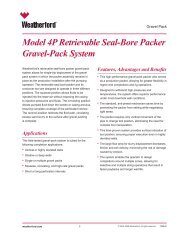
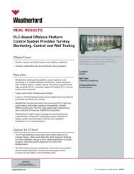
9 5 ⁄8-in. x 12 1 ⁄4-in.<br />
Defyer DPC 516<br />
drillable casing bit.<br />
Liner setting tool.<br />
plemented LD after<br />
experiencing 39.65<br />
days <strong>of</strong> NPT in an<br />
<strong>of</strong>fset well. The NPT,<br />
with a total economic<br />
impact <strong>of</strong> $4.78 million,<br />
resulted from<br />
massive fluid losses<br />
<strong>of</strong> more than 2,500<br />
bbl in a fractured<br />
limestone overlying<br />
the production interval.<br />
This caused<br />
stuck pipe and costly<br />
fishing operations,<br />
and raised the eventuality<br />
<strong>of</strong> running a<br />
contingency liner.<br />
LD was implemented<br />
to case <strong>of</strong>f<br />
the problematic<br />
limestone formation<br />
and land the 9 5 ⁄8-in., 53.5-lb/ft, L-80, Hyd-513 liner in the top <strong>of</strong> the<br />
producing formation, with no <strong>report</strong>ed fluid losses. A five-bladed<br />
PDC bit that could be converted to a drillable drill shoe was used<br />
in this operation.<br />
The CWD bit was designed to function as a PDC bit until total<br />
depth was reached, after which a ball-dropping event blocks the<br />
drilling nozzles from fluid flow. Pressurizing the casing string then<br />
shears the bit’s pins, displacing the steel blades and PDC cutting<br />
structure into the casing-hole open annulus and exposing the cement<br />
ports. The entire cutting structure is eventually displaced into<br />
the annulus and cemented into place.<br />
Passive directional control was maintained in the 75° hole, using<br />
strategically positioned under- and near-gauge stabilizers in the LD<br />
bottomhole assembly (BHA). The CWD bit blades were displaced<br />
and the liner hanger and liner-top packer were each set with success.<br />
The operator saved $5 million and 40 days rig time by eliminating<br />
lost circulation and the need to run a contingency liner.<br />
Complex thief interval<br />
A GoM shelf operator drilling <strong>of</strong>fshore Texas selected LD to deploy<br />
a 7-in. liner and case <strong>of</strong>f a thief interval exhibiting varying degrees<br />
<strong>of</strong> lost-circulation through several adjacent blocks. Planning<br />
meetings between the service provider and operator resulted in the<br />
decision to drill a 7-in., 23-lb/ft HCP-110, GB CDE (casing drilling<br />
enhanced) liner through the catastrophic loss zone and set it in a<br />
competent shale below.<br />
A 7-in. × 8 1 ⁄2-in. CWD bit with a displaceable 13-mm PDC cutting<br />
structure was deemed the most suitable for the application. Its design<br />
features enabled the bit to be converted to a drillable casing<br />
shoe at total depth, allowing for shoe-track drill-out with conventional<br />
PDC or roller-cone bits.<br />
As part <strong>of</strong> the planned LD procedure, a 9 5 ⁄8-in. production casing<br />
was set and cemented in place at 4,150 ft (1,265 m) MD, approximately<br />
50 ft (15.24 m) above the known loss zone. This was followed<br />
by retrieval <strong>of</strong> the 8 ½-in. BHA, rig-up <strong>of</strong> the 7-in. liner-handling<br />
equipment and deployment <strong>of</strong> the liner. Approximately 30 hours<br />
were required to drill the 496-ft <strong>of</strong> new hole through the catastrophic<br />
loss interval and cement the liner in place. The liner was successfully<br />
pressure tested and the liner shoe was successfully tested to<br />
the required 11.5 ppge.<br />
Conclusions<br />
The case histories presented provide a clear indication <strong>of</strong> the benefits<br />
<strong>of</strong> LD technology in difficult drilling environments, including<br />
efficient and accurate liner setting in unstable lost-circulation zones,<br />
a reduced rate <strong>of</strong> fluid loss in the annulus compared to conventional<br />
drilling operations, and a favorable impact on NPT and overall cost<br />
reduction.<br />
Importantly, the use <strong>of</strong> LD was identified as the only viable means<br />
for some <strong>of</strong> these operators to achieve their drilling objectives and<br />
avoid abandoning the well altogether. Complex drilling challenges<br />
<strong>of</strong>ten require unconventional solutions such as liner drilling to play<br />
a key role in a successful outcome. •<br />
Acknowledgment<br />
This article is an abbreviated form <strong>of</strong> “Liner Drilling Technology as a Tool to Reduce<br />
Non-Productive Time: An Update on Field Experiences in the <strong>Gulf</strong> <strong>of</strong> <strong>Mexico</strong>,”<br />
presented at the 2011 AADE National Technical Conference and Exhibition in<br />
Houston.