Lab 7.3.6 Configure Remote Access Using Cisco Easy VPN
Lab 7.3.6 Configure Remote Access Using Cisco Easy VPN
Lab 7.3.6 Configure Remote Access Using Cisco Easy VPN

You also want an ePaper? Increase the reach of your titles
YUMPU automatically turns print PDFs into web optimized ePapers that Google loves.
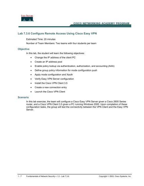
<strong>Lab</strong> <strong>7.3.6</strong> <strong>Configure</strong> <strong>Remote</strong> <strong>Access</strong> <strong>Using</strong> <strong>Cisco</strong> <strong>Easy</strong> <strong>VPN</strong><br />
Objective<br />
Scenario<br />
Estimated Time: 20 minutes<br />
Number of Team Members: Two teams with four students per team<br />
In this lab, the student will learn the following objectives:<br />
• Change the IP address of the client PC<br />
• Create an IP address pool<br />
• Enable policy lookup via authentication, authorization, and accounting (AAA)<br />
• Define group policy information for mode configuration push<br />
• Apply mode configuration and Xauth<br />
• Verify <strong>Easy</strong> <strong>VPN</strong> Server configuration<br />
• Install the <strong>Cisco</strong> <strong>VPN</strong> Client 3.5<br />
• Create a new connection entry<br />
• Launch the <strong>Cisco</strong> <strong>VPN</strong> Client<br />
In this lab exercise, the team will configure a <strong>Cisco</strong> <strong>Easy</strong> <strong>VPN</strong> Server given a <strong>Cisco</strong> 2600 Series<br />
router, and a <strong>Cisco</strong> <strong>VPN</strong> Client 3.5 given a PC running Windows 2000. Upon completion of these<br />
configuration tasks, the group will test the connectivity between the <strong>VPN</strong> Client and the <strong>Easy</strong> <strong>VPN</strong><br />
Server.<br />
1 - 7 Fundamentals of Network Security v 1.0 - <strong>Lab</strong> <strong>7.3.6</strong> Copyright © 2003, <strong>Cisco</strong> Systems, Inc.
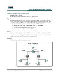
Topology<br />
This figure illustrates the lab network environment.<br />
Preparation<br />
Begin with the topology above and verify the standard router configuration on the pod routers.<br />
<strong>Access</strong> the perimeter router console port using the terminal emulator on the Windows 2000 server. If<br />
desired, save the router configuration to a text file for later analysis. Refer back to the Student <strong>Lab</strong><br />
Orientation if more help is needed.<br />
Before beginning this lab exercise, it is imperative to change the static IP address of the laptop PC to<br />
172.26.26.P (where P =pod number). Also, the PC must be physically connected to a switch port on<br />
VLAN 1.<br />
Tools and resources<br />
In order to complete the lab, the standard lab topology is required:<br />
• Two pod routers<br />
• Two student PCs<br />
• One SuperServer<br />
• Backbone switch and one backbone router<br />
• Two console cables and HyperTerminal<br />
• <strong>Cisco</strong> <strong>VPN</strong> Client 3.5<br />
2 - 7 Fundamentals of Network Security v 1.0 - <strong>Lab</strong> <strong>7.3.6</strong> Copyright © 2003, <strong>Cisco</strong> Systems, Inc.
Additional materials<br />
Further information about the objectives covered in this lab can be found at the following websites:<br />
• http://www.cisco.com/en/US/products/sw/iosswrel/ps1834/products_feature_guide09186a00<br />
8007feb8.html<br />
Command list<br />
• http://www.cisco.com/en/US/products/sw/iosswrel/ps1839/products_feature_guide09186a00<br />
80087d1e.html<br />
In this lab exercise, the following commands will be used. Refer to this list if assistance or help is<br />
needed during the lab exercise.<br />
Command<br />
aaa authentication<br />
aaa new-model<br />
crypto isakmp client<br />
configuration group<br />
{group-name | default}<br />
crypto map map-name<br />
client authentication<br />
list list-name<br />
crypto map map-name<br />
client configuration<br />
address [initiate |<br />
respond]<br />
Description<br />
Use the aaa authorization global configuration<br />
command to set parameters that restrict a user's<br />
network access<br />
Enables AAA.<br />
Specifies which group's policy profile will be defined<br />
and enters Internet Security Association Key<br />
Management Protocol (ISAKMP) group configuration<br />
mode.<br />
If no specific group matches and a default group is<br />
defined, users will automatically be given the default<br />
group's policy.<br />
Enforces Xauth. The list-name argument is used to<br />
determine the appropriate username and password<br />
storage location (local or RADIUS) as defined in the<br />
aaa authentication login command.<br />
<strong>Configure</strong>s the router to initiate or reply to Mode<br />
Configuration requests.<br />
Note that the <strong>Cisco</strong> clients require the respond<br />
keyword to be used. However, if the <strong>Cisco</strong> Secure<br />
<strong>VPN</strong> Client 1.x is used, the initiate keyword must be<br />
used. The initiate and respond keywords may be<br />
used simultaneously.<br />
crypto map map-name<br />
isakmp authorization<br />
list list-name<br />
ip local pool<br />
key name<br />
Enables IKE querying for group policy when<br />
requested by the client. The list-name argument is<br />
used by AAA to determine which storage source is<br />
used to find the policy (local or RADIUS) as defined in<br />
the aaa authorization network command.<br />
<strong>Configure</strong>s a group of local IP address pools<br />
Specifies the IKE pre-shared key for group policy<br />
attribute definition.<br />
Note that this command must be enabled if the client<br />
3 - 7 Fundamentals of Network Security v 1.0 - <strong>Lab</strong> <strong>7.3.6</strong> Copyright © 2003, <strong>Cisco</strong> Systems, Inc.
Command<br />
pool name<br />
username name password<br />
encryption-type<br />
encrypted-password<br />
Description<br />
identifies itself with a pre-shared key.<br />
Defines a local pool address. Although a user must<br />
define at least one pool name, a separate pool may<br />
be defined for each group policy.<br />
Note that this command must be defined and refer to<br />
a valid IP local pool address or the client connection<br />
will fail.<br />
Defines local users for Xauth if RADIUS or TACACS+<br />
is not used.<br />
Use this command only if no external validation<br />
repository will be used.<br />
Step 1 Change the IP Address of the Client PC<br />
a. Before beginning this lab exercise, it is imperative to change the static IP address of the laptop<br />
PC to 172.26.26.P (where P =pod number). Also, the PC must be physically connected to a<br />
switch port on VLAN 1.<br />
Step 2 Create an IP Address Pool<br />
Complete the following step to create an IP address pool for the remote clients on the perimeter<br />
router beginning in the global configuration mode.<br />
a. <strong>Configure</strong> a local pool of IP addresses to be used when a remote peer connects to a point-topoint<br />
interface. The syntax for the ip local pool is:<br />
ip local pool {default | pool-name low-ip-address [high-ip-address]}<br />
i. Use the following IP address pool:<br />
RouterP(config)#ip local pool IPPOOL 10.0.P.20 10.0.P.30<br />
(where P = pod number)<br />
Step 3 Enable Policy Lookup via AAA<br />
To enable policy lookup via AAA, complete the following commands for the perimeter router<br />
beginning in global configuration mode:<br />
a. Enable AAA:<br />
RouterP(config)#aaa new-model<br />
b. Set AAA authentication at login. Note that this command must be enabled to enforce Xauth.<br />
RouterP(config)#aaa authentication login <strong>VPN</strong>AUTHEN local<br />
c. Set AAA authorization at login.<br />
RouterP(config)# aaa authorization network <strong>VPN</strong>AUTHOR local<br />
d. Define local users:<br />
RouterP(config)#username vpnstudent password cisco<br />
4 - 7 Fundamentals of Network Security v 1.0 - <strong>Lab</strong> <strong>7.3.6</strong> Copyright © 2003, <strong>Cisco</strong> Systems, Inc.
Step 4 Define Group Policy Information for Mode Configuration Push<br />
Define the policy attributes that are pushed to the <strong>VPN</strong> Client via mode configuration. Use the<br />
following commands beginning in global configuration mode:<br />
a. Create the ISAKMP policy:<br />
RouterP(config)# crypto isakmp policy 3<br />
RouterP(config-isakmp)# encryption des<br />
RouterP(config-isakmp)# authentication pre-share<br />
RouterP(config-isakmp)# group 2<br />
RouterP(config-isakmp)# exit<br />
RouterP(config)#<br />
b. Specify which group policy profile will be defined and enter ISAKMP group configuration mode. If<br />
no specific group matches and a default group is defined, users will automatically be given the<br />
default group policy. For this exercise, use a group name of “SALES”.<br />
RouterP(config)#crypto isakmp client configuration group SALES<br />
c. Specify the IKE pre-shared key for group policy attribute definition. Note that this command must<br />
be enabled if the <strong>VPN</strong> Client identifies itself with a pre-shared key. For this exercise, use a key<br />
name of “cisco”.<br />
RouterP(isakmp-group)#key cisco123<br />
d. Select a local IP address pool. Note that this command must refer to a valid local IP local<br />
address pool or the <strong>VPN</strong> Client connection will fail. Use the “rempool” pool name.<br />
RouterP(isakmp-group)#pool IPPOOL<br />
e. Define a domain name:<br />
RouterP(isakmp-group)#domain cisco.com<br />
RouterP(isakmp-group)#exit<br />
Step 5 Create the IPSec Transforms<br />
a. Create the transform set to be used with the dynamic crypto map. Name the transform set<br />
“MYSET”. Specify triple-DES for encryptions in the ESP and SHA HMAC authentication in the<br />
ESP.<br />
RouterP(config)# crypto ipsec transform-set MYSET esp-3des esp-sha-hmac<br />
RouterP(cfg-crypto-trans)# exit<br />
Step 6 Create Crypto Maps<br />
a. Create the dynamic crypto map:<br />
RouterP(config)# crypto dynamic-map DYNMAP 10<br />
RouterP(config-crypto-map)# set transform-set MYSET<br />
RouterP(config-crypto-map)# reverse-route<br />
RouterP(config-crypto-map)# exit<br />
b. <strong>Configure</strong> the router to initiate or reply to mode configuration requests. Note that <strong>VPN</strong> Clients<br />
require the respond keyword to be used. The initiate keyword was used with older <strong>VPN</strong> Clients<br />
and is no longer used with the 3.x version <strong>VPN</strong> Clients.<br />
RouterP(config)#crypto map CLIENTMAP client configuration address<br />
respond<br />
5 - 7 Fundamentals of Network Security v 1.0 - <strong>Lab</strong> <strong>7.3.6</strong> Copyright © 2003, <strong>Cisco</strong> Systems, Inc.
c. Enable IKE querying for group policy when requested by the <strong>VPN</strong> Client. The list-name<br />
argument is used by AAA to determine which storage is used to find the policy, local or RADIUS,<br />
as defined in the aaa authorization network command.<br />
RouterP(config)#crypto map CLIENTMAP isakmp authorization list<br />
<strong>VPN</strong>AUTHOR<br />
d. Enforce Xauth. The list-name argument is used to determine the appropriate username and<br />
password storage location, local or RADIUS, as defined in the aaa authentication login<br />
command.<br />
RouterP(config)#crypto map CLIENTMAP client authentication list<br />
<strong>VPN</strong>AUTHEN<br />
e. Assign the dynamic crypto map to CLIENTMAP:<br />
RouterP(config)# crypto map CLIENTMAP 10 ipsec-isakmp dynamic DYNMAP<br />
f. Assign the crypto map to the outside interface:<br />
RouterP(config)# interface fa0/1<br />
RouterP(config-if)# crypto map CLIENTMAP<br />
RouterP(config-if)# exit<br />
Step 7 Verify <strong>Easy</strong> <strong>VPN</strong> Server Configuration<br />
a. To verify the configurations for this feature, use the following command in EXEC mode:<br />
RouterP#show crypto map {interface interface | tag map-name}<br />
This command displays the crypto map configuration.<br />
Step 8 Install the <strong>Cisco</strong> <strong>VPN</strong> Client 3.5<br />
Complete the following steps to install the <strong>Cisco</strong> <strong>VPN</strong> Client version 3.5 on the Windows 2000 Server<br />
PC:<br />
a. Open the <strong>VPN</strong> Client desktop folder.<br />
b. Locate and run the <strong>Cisco</strong> <strong>VPN</strong> Client setup.exe executable. If this is the first time the <strong>VPN</strong> Client<br />
is installed, a window opens and displays the following message: Do you want the installer to<br />
disable the IPSec Policy Agent?<br />
c. Click Yes to disable the IPSec policy agent. The Welcome window opens.<br />
d. Read the Welcome window and click Next. The License Agreement window opens.<br />
e. Read the license agreement and click Yes. The Choose Destination Location window opens.<br />
f. Click Next. The Select Program Folder window opens.<br />
g. Accept the defaults by clicking Next. The Start Copying Files window opens.<br />
The files are copied to the hard disk drive of the PC and the InstallShield Wizard Complete<br />
window opens.<br />
h. Select Yes, I want to restart my computer now and click Finish. The PC restarts.<br />
This completes the installation of the <strong>Cisco</strong> <strong>VPN</strong> Client (Software Client).<br />
Step 9 Create a New Connection Entry<br />
Complete the following steps to create a new <strong>VPN</strong> connection entry:<br />
a. Choose Start > Programs > <strong>Cisco</strong> Systems <strong>VPN</strong> Client > <strong>VPN</strong> Dialer. The <strong>Cisco</strong> Systems<br />
<strong>VPN</strong> Client window opens.<br />
b. Click New. The New Connection Entry wizard opens.<br />
6 - 7 Fundamentals of Network Security v 1.0 - <strong>Lab</strong> <strong>7.3.6</strong> Copyright © 2003, <strong>Cisco</strong> Systems, Inc.
c. Enter Boston Sales in the connection entry field.<br />
d. Click Next.<br />
e. Enter a public interface IP address of 172.30.P.2 in the remote server field.<br />
(where P = pod number)<br />
f. Click Next.<br />
g. Select Group <strong>Access</strong> Information and complete the following substeps. The following entries<br />
are always case sensitive.<br />
• Enter a group name, SALES.<br />
• Enter the group password, cisco123.<br />
• Confirm the password, cisco123.<br />
h. Click Next.<br />
i. Click Finish and leave the <strong>Cisco</strong> Systems <strong>VPN</strong> Client window open.<br />
The network parameters for the <strong>VPN</strong> Client have been configured and a new <strong>VPN</strong> private<br />
networking connection entry has been created successfully.<br />
Step 10 Launch the <strong>Cisco</strong> <strong>VPN</strong> Client<br />
Complete the following steps to launch the <strong>Cisco</strong> <strong>VPN</strong> client on the PC:<br />
a. Choose Start > Programs > <strong>Cisco</strong> Systems <strong>VPN</strong> Client > <strong>VPN</strong> Dialer.<br />
b. Verify that the connection entry is Boston Sales.<br />
c. Verify that the IP address of remote server is set to the perimeter router public interface IP<br />
address of 172.30.P.2.<br />
(where P = pod number)<br />
d. Click Connect. The Connection History window opens and several messages flash by quickly.<br />
Complete the following substeps:<br />
i. When prompted for a username, enter vpnstudent.<br />
ii. When prompted to enter a password, enter cisco.<br />
iii. Click OK. The following messages flash by quickly:<br />
Initializing the connection<br />
Contacting the security gateway at<br />
Authenticating user<br />
The window disappears and a <strong>VPN</strong> lock icon appears in the system tray. The <strong>VPN</strong> Client has<br />
been successfully launched.<br />
7 - 7 Fundamentals of Network Security v 1.0 - <strong>Lab</strong> <strong>7.3.6</strong> Copyright © 2003, <strong>Cisco</strong> Systems, Inc.