VOLUME - Urban Administration & Development Department
VOLUME - Urban Administration & Development Department
VOLUME - Urban Administration & Development Department

Create successful ePaper yourself
Turn your PDF publications into a flip-book with our unique Google optimized e-Paper software.
GOVERNMENT OF MADHYA PRADESH,<br />
URBAN ADMINISTRATION AND DEVELOPMENT DEPARTMENT<br />
INTEGRATED STANDARD SCHEDULE OF RATES<br />
(4 <strong>VOLUME</strong>S)<br />
<strong>VOLUME</strong> - 3<br />
ROAD & BRIDGE WORKS<br />
INFORCE FROM<br />
1st JUNE 2011<br />
ISSUED BY<br />
COMMISSIONER<br />
<strong>Urban</strong> <strong>Administration</strong> and <strong>Development</strong> <strong>Department</strong><br />
Government of Madhya Pradesh, Bhopal
FOREWORD<br />
The 74 th Constitutional Amendment has created a focus on improving and strengthening<br />
<strong>Urban</strong> infrastructure and systems in <strong>Urban</strong> Local Bodies. With the availability of<br />
substantial funds from various sources and with our own increased revenues, shortage<br />
of development funds is no longer a major constraint for development. However<br />
ensuring the effective utilization of available funds is a major concern.<br />
Procurement processes in the <strong>Urban</strong> Local Bodies is one such area which requires<br />
basic system improvement and transparency. Estimating the cost of works correctly<br />
prior to the execution is one of the major challenges. Till now, <strong>Urban</strong> <strong>Administration</strong> and<br />
<strong>Development</strong> <strong>Department</strong>, Government of Madhya Pradesh did not have its own<br />
Standard Schedule of Rates which forms a basis for estimating the costs of various<br />
Building and Infrastructure works including Water Supply, Drainage, Road, Sewerage<br />
and Sanitation and Electrical Works. Presently <strong>Urban</strong> Local Bodies have to depend on<br />
Schedule of Rates of various Works <strong>Department</strong>s of the State Government such as MP<br />
Public Health Engineering <strong>Department</strong>, Public Works <strong>Department</strong>, Water Resource<br />
<strong>Department</strong> etc. for civil works and Madhya Pradesh State Electricity Board for electrical<br />
works. The infrastructure and maintenance works done by our <strong>Urban</strong> Local Bodies are<br />
town specific as well as need specific and therefore, new items are required to be<br />
created which are currently not mentioned in these SoRs. Hence the <strong>Department</strong> of<br />
<strong>Urban</strong> <strong>Administration</strong> and <strong>Development</strong> has decided to develop its own Integrated<br />
Standard Schedule of Rates for all Building and Infrastructure and maintenance works<br />
keeping in view the current and future requirements of the <strong>Urban</strong> Local Bodies.<br />
I am extremely happy that the <strong>Department</strong>, with the assistance of Project Utthan,<br />
Madhya Pradesh <strong>Urban</strong> Services for the Poor (MPUSP), a DFID assisted programme<br />
has taken up this task and have completed it.<br />
To complete this task, a 18 member Working Group was formed vide order number<br />
;kaiz/7/09/2442 dated 12th October 2009. This Working Group decided about the various<br />
items required by <strong>Urban</strong> Local Bodies to carry out the infrastructure development and<br />
construction works smoothly, and to be included in the ISSR.
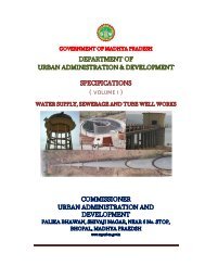
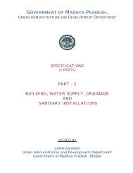
The ISSR is prepared in four parts i.e. Volume - 1 Water Supply, Sewerage & Tube well<br />
works, Volume - 2 Building works, Volume - 3 Road & Bridge works, Volume - 4<br />
Electrical works. Specifications for various works have also been illustrated in three<br />
separate volumes.<br />
An Output Review Panel was also constituted vide order number<br />
MPUSP/Engg./SSRs/10/439, Bhopal Dated 23-7-2010. The Output Review Panel<br />
reviewed the process outputs and finalized various reports including Rate Analysis for<br />
various items under Integrated Standard Schedule of Rates.<br />
All the volumes of the ISSR along with the applications are also available on the<br />
Website of UADD (mpurban.gov.in). Arrangements have been made for annual<br />
updation of the ISSR. This will help the <strong>Urban</strong> Local Bodies in preparing cost estimates<br />
close to the prevailing market values and hence, avoid high tender rates.<br />
I extend my sincere thanks to the Project Director, Project Utthan, MPUSP, UADD,<br />
Bhopal and to all the members of Working Group and the Output Review Panel for<br />
taking keen interest in completing the voluminous job of preparation & completion of<br />
ISSR well in time.<br />
I am sure that this Integrated Standard Schedule of Rates will be quite useful for all the<br />
construction, development and maintenance works of <strong>Urban</strong> Local Bodies of Madhya<br />
Pradesh.<br />
(S.N. Mishra)<br />
Commissioner<br />
<strong>Urban</strong> <strong>Administration</strong> and <strong>Development</strong><br />
Government of Madhya Pradesh<br />
Bhopal
MEMBERS OF WORKING GROUP<br />
1. Shri K. K. Shrivastava, Chief Engineer, Directorate of <strong>Urban</strong><br />
<strong>Administration</strong> and <strong>Development</strong>, Bhopal<br />
2. Shri C. S. Sankule, Chief Engineer, Project Uday, <strong>Department</strong> of <strong>Urban</strong><br />
<strong>Administration</strong> and <strong>Development</strong>, Bhopal<br />
3. Shri Ashok Khare, Superintending Engineer, Directorate of <strong>Urban</strong><br />
<strong>Administration</strong> and <strong>Development</strong>, Bhopal<br />
4. Shri R.N. Songara, Superintending Engineer, Directorate of <strong>Urban</strong><br />
<strong>Administration</strong> and <strong>Development</strong>, Bhopal<br />
5. Shri S.K. Sogani, Superintending Engineer, Deputy Director office,<br />
UADD, Jabalpur<br />
6. Shri J.M. Dagaonkar Superintending Engineer, Municipal Corporation,<br />
Ujjain<br />
Chairman<br />
Member<br />
Member<br />
Member<br />
Member<br />
Member<br />
7. Shri H.K. Jain Superintending Engineer, Municipal Corporation, Indore Member<br />
8. Shri S.K. Devgan Deputy City Engineer, Municipal Corporation, Bhopal Member<br />
9. Shri K.K. Shrivastava Executive Engineer, Municipal Corporation,<br />
Gwalior<br />
10. Shri B.K. Sonwani, Executive Engineer, Deputy Director office, UADD,<br />
Sagar<br />
11. Shri A.G. Khan, Executive Engineer, Deputy Director office, UADD,<br />
Bhopal<br />
12. Shri Avinash Dubey Incharge Executive Engineer., Deputy Director<br />
office, UADD, Rewa<br />
13. Shri Pradeep Nigam Incharge Executive Engineer, Deputy Director<br />
office, UAD, Indore<br />
Member<br />
Member<br />
Member<br />
Member<br />
Member<br />
14. Shri Anand Singh, Assistant Engineer, Directorate of UAD Member<br />
15. Shri Rakesh Rawat, Assistant Engineer, Municipal Council,<br />
Hoshangabad<br />
Member<br />
16. Shri P.P. Kaithwas, Assistant Engineer, Municipal Council, Neemuch Member<br />
17. Shri J.P. Gupta Former Deputy Director (Engineering) MSU, MPUSP,<br />
UADD, Bhopal<br />
18. Shri S.K. Goyal Engineering Consultant MPUSP Technical<br />
Consultancy Team, Bhopal<br />
Member<br />
Secretary<br />
Member
MEMBERS OF OUTPUT REVIEW PANEL<br />
1. Shri Ashok Khare, Chief Engineer (In Charge), Directorate<br />
of <strong>Urban</strong> <strong>Administration</strong> and <strong>Development</strong>, Bhopal<br />
2. Shri M.J.S Tulsi, Deputy Director (Engineering), Project<br />
Utthan, Municipal Support Unit, MPUSP, <strong>Department</strong> of<br />
<strong>Urban</strong> <strong>Administration</strong> and <strong>Development</strong>, Bhopal<br />
3. Shri Kamlesh Bhatnagar, Assistant Engineer, Project<br />
Utthan, Municipal Support Unit, MPUSP, <strong>Department</strong> of<br />
<strong>Urban</strong> <strong>Administration</strong> and <strong>Development</strong>, Bhopal<br />
4. Shri Shyam Mehndi Ratta, Engineering Consultant, MPUSP<br />
Technical Consultancy Team, Bhopal<br />
5. Shri Sunil Koul, Engineering Consultant, MPUSP Technical<br />
Consultancy Team, Bhopal<br />
6. Shri Harsh Vardhan Sharma, Engineering Consultant,<br />
MPUSP Technical Consultancy Team, Bhopal<br />
7. Shri Sanjay Saxena, E-Governance Consultant, MPUSP<br />
Technical Consultancy Team, Bhopal<br />
8. Shri Ashwin Lamba, E-Governance Consultant, MPUSP<br />
Technical Consultancy Team, Bhopal<br />
Chairman<br />
Convener<br />
Special Invitee<br />
Member<br />
Member<br />
Member<br />
Member<br />
Member
Chapter<br />
No.<br />
INDEX<br />
Description<br />
ROAD<br />
Page No.<br />
GENRAL NOTES 1 - 11<br />
1 Carriage of Material 12<br />
2 Site Clearance 13 - 16<br />
3 Earth work, Erosion control and Drainage 17 - 23<br />
4 Sub-Bases, Bases (Non-Bituminous) and Shoulders 24 - 31<br />
5 Bases and Surface courses (Bituminous) 32 - 54<br />
6 Cement Concrete Pavements 55 - 62<br />
7 Geosynthetics and Reinforced Earth 63 - 66<br />
8 Traffic Signs, Marking & other Road Appurtenances. 67 - 73<br />
9 Supply of Material 74<br />
10 Maintenance of Roads 75 - 78<br />
11 Horticulture for Roads 79 - 81<br />
12 Survey & Investigation,Preparation of D.P.R. and other<br />
Miscellaneous items.<br />
82<br />
BRIDGE<br />
13 Foundations 83 - 90<br />
14 Sub-Structure 91 - 100<br />
15 Super-Structure 101 - 107<br />
16 River Training and Protection works 108 - 110<br />
17 Repair and Rehabilitation 111 - 114
1<br />
2<br />
GENERAL NOTES<br />
The SOR of UADD <strong>Department</strong> consists of 4 Volumes<br />
<strong>VOLUME</strong> - I Water Supply, Sewerage & Tube Well Works<br />
<strong>VOLUME</strong> - II Building Works<br />
<strong>VOLUME</strong> - III Road & Bridge Works<br />
<strong>VOLUME</strong> - IV Electrical Works<br />
The contents of each Volume are given below<br />
<strong>VOLUME</strong> - I<br />
WATER SUPPLY, SEWERAGE AND TUBE WELL WORKS<br />
1 Cast Iron Pipes and Specials with with Socket & Spigot lead joints.<br />
2 Cast Iron Tyton Pipes with Tyton Joints.<br />
3 Cast Iron Pipes and Specials with flanged joints.<br />
4 Ductile Iron Pressure Pipes and Special with Tyton joints.<br />
5 Unplasticized PVC Pipes & Fittings for potable water supply.<br />
6 Cast Iron Valves.<br />
7 Galvanised Iron Pipes, Specials and Gun Metal/Brass Metal Fittings.<br />
8 HDPE Pipes and Specials.<br />
9 GRP Pipes and Specials.<br />
10 Asbestos Cement Pressure Pipe and Cast Iron Fittings.<br />
11 Salt Glazed Stoneware Pipes.<br />
12 Unplasticized Non-Pressure Polyvinyl Chloride (PVC-U) Pipes for use in underground sewerage<br />
system.<br />
13 Reinforced Cement concrete Pipes.<br />
14 Sewer Appurtenances.<br />
15 Civil Works for Water Supply & Sewerage works.<br />
16 Miscellaneous.<br />
17 Drawings for Water Supply & Sewerage.<br />
18 Drilling of Tube Wells.<br />
1 Carriage of Material<br />
2 Earth work<br />
3 Mortars<br />
4 Concrete work<br />
5 Reinforced Cement Concrete<br />
6 Brick work<br />
7 Stone work<br />
8 Marble work<br />
9 Wood Work & P.V.C. Works<br />
10 Steel work<br />
11 Flooring<br />
12 Roofing and Ceiling<br />
13 Finishing<br />
14 Repair to Building<br />
15 Dismantling & Demolishing<br />
16 Pile work<br />
17 Aluminium work<br />
18 Water proofing<br />
19 Horticulture & Landscaping<br />
20 Form Work<br />
<strong>VOLUME</strong> - II<br />
BUILDING WORKS<br />
2
21 Hire Charges of Machine<br />
22 Rainwater Harvesting, Recycle and Reuse wastewater<br />
23 Building Water Supply<br />
24 Building Drainage<br />
25 Sanitary Installation<br />
<strong>VOLUME</strong> - III<br />
ROAD & BRIDGES WORKS<br />
ROAD<br />
1 Carriage of Material<br />
2 Site Clearance<br />
3 Earth work, Erosion control and Drainage<br />
4 Sub-Bases, Bases (Non-Bituminous) and Shoulders<br />
5 Bases and Surface courses (Bituminous)<br />
6 Cement Concrete Pavements<br />
7 Geosynthetics and Reinforced Earth<br />
8 Traffic Signs, Marking & other Road Appurtenances<br />
9 Supply of Material<br />
10 Maintenance of Roads<br />
11 Horticulture<br />
12 Survey & Investigation, Preparation of D.P.R. and other Miscellaneous items<br />
BRIDGE<br />
13 Foundations<br />
14 Sub-Structure<br />
15 Super-Structure<br />
16 River Training and Protection works<br />
17 Repair and Rehabilitation<br />
<strong>VOLUME</strong> - IV<br />
ELECTRICAL WORKS<br />
PART – 1 – INTERNAL ELECTRIFICATION<br />
1 Wiring in surface /concealed rigid P.V.C. conduit system.<br />
2 Wiring in surface /concealed rigid Steel conduit system.<br />
3 Wiring in surface rigid P.V.C. casing capping system<br />
4 Wiring in existing/conduit/P.V.C. casing capping system<br />
5 Sub Mains in surface/concealed rigid steel conduit system.<br />
6 Rewiring in existing conduit.<br />
7 Control switch gear/Bus bar.<br />
8 MCCB’s, Isolators, MCB’s, MCB-DB and fixing.<br />
9 Accessories/Pannel/Lamp/Telephone wires/Fens/Luminaries.<br />
10 Miscellaneous<br />
11 Earthing<br />
12 Dismantiling of Civil and Electrical Works.<br />
PART – 2 – EXTERNAL ELECTRIFICATION<br />
13 External Electrification and Over head lines<br />
14 Power Cable & laying<br />
15 Transformers. & Fire Extinguishers<br />
16 High Mast<br />
17 Pump Sets with G.I. Pipe<br />
18 Solar street light system<br />
19 Supply of materials<br />
3
3<br />
3.1<br />
3.2<br />
3.3<br />
3.4<br />
3.5<br />
Rate for completed items include the cost of followings: -<br />
Material,labour, templates, tools, hire and running charges of plant/machinery required to complete the<br />
work,unless specified otherwise.<br />
All lead & lift of all material required for execution of work inclusive of charges like<br />
duties,tax,royalty,insurance etc.<br />
Provision for erection and removal of centering, form works, scaffolding, benching ladders and all other<br />
applications etc.,required for the proper execution of the work unless otherwise specified.<br />
Provision for covering necessary to protect the work/structure from inclement weather etc.and damage<br />
arising from falling materials, rain,fire etc shall be the responsibility of contractor.<br />
Curing wherever required including arrangement of water and also including its lead or lift whatsoever.<br />
4<br />
5<br />
6<br />
The mode of measurements shall be as per provisions contained in the relevant chapters and in<br />
specifications/relevant IS codes.<br />
All materials shall conform to the relevant prevailing Indian Standard Specifications. All material before<br />
use in works shall require approval of the Engineer in charge, who will get them sampled, tested as per<br />
relevant IS code at contractor's cost and samples so approved shall be kept in the office of the<br />
concerned Engineer-in-charge till finalization of the work.<br />
Material obtained from excavation shall be the property of the Local body (Municipal Corporation,<br />
Municipal Council & Nagar Panchayat).<br />
7<br />
8<br />
8.1<br />
8.2<br />
Hard Rock available from excavation, shall be used for conversion into coarse aggregates or for other<br />
construction material and shall be issued to the contractor on the rate as decided by competent<br />
authority.<br />
Cement :-<br />
Where contract provides for cement to be arranged by the Contractor himself, only I.S.I. Marked<br />
cement as per IS for 33 grade cement, IS 269 for 43 grade cement, IS 8112 for 53 grade cement, IS<br />
12269 for Portland Pozzolana cement, IS 1489 Part - I & II specifications shall be allowed to be used in<br />
the work subject to the prescribed tests.<br />
Make of cement shall be got approved by the Engineer-in-charge. The engineer in charge shall get<br />
cement tested as per relevant IS codes, at the cost of the contractor, before use in work.<br />
8.3<br />
8.4<br />
Pozzolona cement is now being widely produced all over the country. This may be used in structures as<br />
per provisions of IS code.<br />
When the strength of concrete required upto M-30, then O.P.C. 33 grade conforming to IS 269-1989 or<br />
P.P.C. conforming to IS : 1489-1991 may be used.<br />
8.5<br />
When the strength of concrete required is more than M-30, the O.P.C. 43 grade conforming to IS :<br />
8112-1989 shall be used.<br />
8.6<br />
For prestressed concrete works where the strength of concrete required is more than M-30, then<br />
O.P.C. 53 grade cement conforming to IS : 12269-1987 shall be used.<br />
4
8.7<br />
8.8<br />
In specific cases requiring higher grade of strength, use of Ordinary Portland Cement (OPC) should be<br />
invariably ensured.<br />
The arrangement for necessary equipment and testing shall have to be made by the contractor himself<br />
at site, as decided by the Engineer-in-Charge. All expenses shall be borne by the contractor.<br />
8.9<br />
8.10<br />
Any lot of cement brought to site by the contractor, would be permitted to be used in the work only after<br />
the satisfactory results of the tests, under the supervision of the Engineer-in-Charge or his authorised<br />
representative. The record of the test results shall be maintained in register mentioned in subsequent<br />
para.<br />
A duplicate register as prescribed by the competent authority of technical authority shall be maintained<br />
at the site of the work. Extract certified copies of the entries for each month shall be submitted to the<br />
Engineer-in-Charge by the Contractor.<br />
8.11<br />
The original register shall also be submitted to the Engineer-in-Charge on completion of the work by the<br />
Contractor.<br />
9<br />
9.1<br />
9.2<br />
9.3<br />
Steel :-<br />
Steel used for reinforcement shall conform as per under :-<br />
(a) Mild Steel and medium tensile steel bars shall conform to IS : 432 (Part-I),<br />
(b) Hot rolled deformed bars shall conform to IS : 1139,<br />
(c) Cold twisted bars shall conform to IS : 1786,<br />
(d) Hard drawn steel wire fabric shall conform to IS : 1566 and<br />
(e) Rolled steel made from structural steel shall conform to IS : 226.<br />
All reinforcement shall be free from loose mill scales, loose rust and coats of paints, oil, mud or other<br />
coatings which may destroy or reduce bond.<br />
Only such steel obtained from main producers of steel i.e. SAIL, IISCO, TISCO or such steel rolling<br />
mills as having licence from the B.I.S. to manufacture such steel for reinforcements, shall be allowed to<br />
be used in the work. The make of the steel shall be approved by engineer-in-charge.<br />
9.4<br />
9.5<br />
The Contractor shall have to produce Test Certificate in the proforma prescribed approved by B.I.S.<br />
from the manufacturer for every batch of steel brought to the site of work.<br />
Before commencement of use of steel, from any batch brought to site the of the work by the contractor,<br />
the Engineer-in-Charge shall arrange to get samples tested for nominal mass, tensile strength, bend<br />
test and rebend test from any Laboratory of his choice at the cost of Contractor. The selection of test<br />
specimens and frequency shall be as per relevant I.S. specification of the steel used.<br />
10<br />
If any item of work is found not upto the prescribed standard but the Engineer-in-charge is of the<br />
opinion that the same is structurally adequate and can be accepted at a reduced rate, then in such<br />
case, the Engineer-in-charge shall submit proposal for the same, supported by an analysis in<br />
justification thereof, through proper channel to the chief engineer UADD to obtain his approval<br />
expeditiously (ordinarily within 15 days). The approved analysis along with orders of the chief engineer<br />
should be appended to the final bill of the contractor.<br />
5
11<br />
In case of any contradiction in the provisions of the specifications and this schedule of rates, the<br />
decision of Chief Engineer, UADD will be of precedence.<br />
12<br />
13<br />
14<br />
(a) Rates of items would apply for work order/piece work system also.<br />
(b) Rates payable for any work to be done departmentally then rates should be reduced by 10.434%<br />
(contractor profit percentage 10% + T&P charge 2%) i.c. 100x12/115 = 10.434%.<br />
Interpretations :- The Chief Engineer, UADD, Bhopal shall be the sole deciding Authority as to the<br />
meaning, interpreation and implications of various provisions in this schedule of rates. His decision<br />
shall be final and binding on all concerned.<br />
Safety :- The contractor shall be fully and solely responsible for making all the safety arrangements<br />
pertaining to the work. The contractor shall be fully responsible and liable in all respects for any<br />
accidents and subsequent legal action initiated by any party including the department.<br />
15<br />
Latest I.S. Codes with upto date amendments shall be applicable.<br />
16<br />
16.1<br />
Concrete Work : -<br />
Testing of Concrete :- The concrete shall be sampled in accordance with the norms specified in IS 456.<br />
The frequency of sampling is given below.<br />
Note:<br />
(i) At least one sample shall be taken from each shift.<br />
(ii) Where concrete is produce as continuous production unit, such as ready mix concrete plant. The<br />
frequency of sampling may be agreed upon mutually by suppliers and purchasers.<br />
16.2<br />
16.3<br />
Test specimen<br />
Three test specimen shall be made for each sample for testing at 28 days. Additional samples may be<br />
required for various purposes such as to determine the strength of concrete at 7 days or at the time of<br />
striking the formwork, or to determine the duration of curing, or to check the testing error. Additional<br />
samples may also be required for testing samples cured by accelerated methods as described in IS<br />
9103. The specimen shall be tested as described in IS 516.<br />
Nominal mix concrete may be used for concrete for M-20 or lower. The proportions of material for<br />
nominal mix concrete shall be in accordance with the table given below: -<br />
6
16.4<br />
Note:-<br />
The proportions of the fine to coarse aggregate should be adjusted from upper limit to lower limit<br />
progressively as the grading of fine aggregate become finer and the maximum size of coarse<br />
aggregate becomes lower. Granded coarse aggregate shall be used.<br />
Design mix concrete is preferred to nominal mix. If design mix concrete can not be used for any reason<br />
on the work for grades of M-20 or lower. Nominal mixes may be used with the permission of Engineer<br />
in charge, which, however, is likely to involve a higher cement content.<br />
17<br />
18<br />
Best shall mean that in the opinion of the concerned Engineer-in-Charge, there is no superior material<br />
or article or class of workmanship obtainable in the market.<br />
The labour only provided in the Schedule of Rates includes the cost of all labour including necessary<br />
handling of the materials at site of work and all workmanship. The labour rates adopted for preparation<br />
of S.O.R. are inclusive of provision for weekly holiday.<br />
Extra Notes For Road Work<br />
1<br />
2<br />
3<br />
4<br />
5<br />
6<br />
7<br />
The girth of trees shall be measured at 1.00 meter (One meter) above ground level.<br />
Rates of site clearance include jungle clearance levelling and dressing.<br />
All wood obtained from the tree shall be property of the government and shall be handed over to<br />
Engineer in charge.<br />
The rates include making arrangement of traffic as per MORTH clause 112 except for initial treatment<br />
to verge, shoulders and construction of diversion.<br />
The rates include all cleaning operation. The rates also include provision of coir rope being used for<br />
premix carpet and surface dressing for providing support to edges.<br />
The rates for completed items in the schedule of rates also include the following.<br />
1 10% for contractor profit<br />
2 2% for T&P<br />
3 3% for over head charges<br />
The labour rate only provided in the Schedule of Rates includes the cost of all labour, including<br />
necessary handling of the materials at site of work, all workmanship unless otherwise specified.<br />
8<br />
The rates also include the element of testing of samples of various materials brought by the contractor<br />
for use on the work, as well as other necessary tests for items of work as stipulated in the UADD<br />
specifications of road & bridge & MORTH specification.Frequency of such tests to be carried out must<br />
not be less than the prescribed frequencies. Copies of registers,containing records of tests shall have<br />
to be presented along with running account bills.Register (original) shall have to be submitted along<br />
with the inal bill. Actual consumption of materials like bitumen,cement & steel worked out in each<br />
running bill before making payment. Tests shall have to be conducted by the contractor's Engineer<br />
under the supervision of the Engineer-in- Charge or his authorised representatives.<br />
7
The contractor shall have to establish a field laboratory at the site of work, if the amount of contract<br />
exceeds Rs.25.00 lakhs.In other cases, testing of construction materials should be got done from any<br />
of the tests laboratories of the various Government <strong>Department</strong>s, Government/Semi Govt. under<br />
takings and Technical Institutes, Engineering College, Polytechnic, I.T.I, recognized and authorized lab.<br />
8.1<br />
8.2<br />
8.3<br />
9<br />
10<br />
The work should not be accepted in any case, if the contractor fails to observe the instructions of the<br />
department, regarding testing of materials.<br />
Before making any payment, it will be the responsibility of the officers making payment to assure that all<br />
tests as per prescribed frequencies, have been carried out, and found as per requirement. The<br />
frequency for CBR Test is one test per 500 cum or part there of. The frequency for deleterious material<br />
is also one test per 500 cum or part thereof.<br />
If tests are not conducted to the prescribed frequency, the Engineer in- Charge should reject that part of<br />
the work.<br />
Specification of UADD <strong>Department</strong> for road & bridge and specification for road & bridge published by<br />
I.R.C. of MORTH works shall be applicable.<br />
For comprehensive items, quantities of aggregates, screenings, granular materials and binding<br />
materials etc. indicated in the specifications are loose. No extras on account of any voids or bulkages<br />
etc. will be paid separately. Where it is proposed only to supply, transport and stack the mineral then<br />
aggregates payment for the same shall be regulated on the basis of volumes to be computed after<br />
deductions specified as below. The stacking will have to be in a trapezoidal section having base 1.5 M.,<br />
top width 0.5 M. and height 0.5 M. The length should be as long as conveniently possible.<br />
As Per MORTH Table No.500-28<br />
11<br />
12<br />
13<br />
14<br />
For construction of reinforced earth retaining wall, back filling shall be paid separately as per Chapter-3<br />
"Earth work, erosion control and drainage"<br />
For WBM Grade-I and Grade-II broken stone can be used, for WBM Grade-III crushed stone shall be<br />
used.<br />
Metal to be used for all bituminous courses and cement concrete shall be crushed in mechanical<br />
crushers.<br />
The use of vibratory roller is essential for all the items where ever compaction/consolidation is to be<br />
done with rollers unless specified otherwise.<br />
8
15<br />
The surface regularity of the completed sub-grade, sub-base, base courses, widening of surfaces and<br />
bituminous courses in the longitudinal and transverse directions shall be within the tolerances indicated<br />
in the table below of the specifications. For checking, specifications UADD or MORTH clause 902 shall<br />
apply.<br />
16<br />
17<br />
The work of shoulders must proceed the work of sub-base and base courses and succeed the<br />
bituminous courses and cement concrete pavement.<br />
The measurements of rock excavation are to be done as per MORTH clause 301.8. However, if the<br />
excavated rock is utilized by conversion into aggregates also, then a deduction at the rate of 45% shall<br />
be made from the stacked quantity of aggregates. To compute the volumes of rock excavation size of<br />
the stacks should be as large as convenient.<br />
18<br />
(a)<br />
(b)<br />
19<br />
Wherever an existing boulder soling or WBM pavement is required to be excavated, it shall be<br />
presumed that the following quantities of rubble and coarse aggregates would be available for re-use<br />
and issued to the contractor at the rate decided by competent authority for technical sanction.<br />
Rubble: - 1 cubic meter of rubble for every cubic meter of excavated boulder soling .<br />
W.B.M: - 1 cubic meter of W.B.M for every cubic meter of excavated WBM ( Excavated W.B.M should<br />
be screened to segregate metal from moorum before re-use.)<br />
For each compacted cubic meter items of bituminous, base and surface courses the approximate loose<br />
quantities required will be 1.4 cubic meter unless other wise specified.<br />
20 For items of BUSG (Built-Up Spray Grout), surface dressing and seal coat type-A, the aggregates shall<br />
be stacked at site, measured and recorded in M.B. prior to their use on work. No separate payment<br />
shall be made for stacking and payment for these items. These items shall be regulated as per SOR<br />
items.<br />
9
21<br />
Where laying of open graded premix carpet (OGPC) or seal coat Type-B with mechanical mixing is not<br />
feasible, use of other Mixers are a must for open graded premix carpet or seal coat Type 'B' using<br />
bitumen/emulsion, but this can be used only with prior approval of chief engineer UADD.<br />
22<br />
Rates for the items of semi-dense bituminous concrete, dense bituminous macadam and bituminous<br />
concrete are based on the assumption that the bitumen at the rate of 5%, 4.25% and 5% respectively<br />
would be required. In case, lesser or more bitumen is required as per the job mix formula. Difference of<br />
bitumen shall be paid or deducted as per actual consumption of quantity of bitumen.<br />
23<br />
Only cement of required specifications at the rate of 2% by weight of total aggregate will be used as<br />
filler for bituminous work wherever filler is to be provided. Lime shall not be used as filler.<br />
24<br />
25<br />
26<br />
27<br />
28<br />
The pavement camber or cross fall shall be provided as per provisions of IRC-73-1980.<br />
Bitumen & modified bitumen shall be obtained from reputed oil refineries and emulsion should be ISI<br />
marked only.<br />
Dismantling of utilities will be done under the supervision of concerned departments with prior<br />
information to the users.<br />
For narrow and restricted areas, plate compactors shall be used for compaction to achieve the desired<br />
density.<br />
The actual quantities of materials shall be as per job mix formula for bituminous works.<br />
29<br />
Reflective sign board should not be installed on M.D.R. and on any other road having traffic intensity<br />
less than 450 commercial vehicles per day without prior approval of the competent authority for<br />
sanction.<br />
Extra Notes for Bridge Works :-<br />
1 Foundation :<br />
(i)<br />
All works below ground level or low water level, whichever is higher but not above soffit level shall be<br />
termed as foundation work.<br />
(ii)<br />
Low water level shall be the average water level met with at the time of doing the foundation work. The<br />
maximum and minimum water levels should be recorded by the Assistant Engineer, just before starting<br />
the particular foundation and within a reasonable time at the close of that foundation work, the average<br />
of these two levels will be the L.W.L. for that foundation work. In case of major bridges such records will<br />
be taken by the Executive Engineer.<br />
2 Sub Structure<br />
The part of the bridge structure below the<br />
(a)Soffit level of the deck slab/beams and or<br />
(b)Springing level for arch spans, but above the ground level or L.W.L. which ever is higher, shall be<br />
taken as sub structure of the bridge part. Complete RCC box section will also be considered as substructure.<br />
10
3 Super Structure<br />
The work above<br />
(a)Soffit level for deck slabs/beams and<br />
(b)Springing level for arch span, including kerbs, railing, expansion joints, beams, slabs etc. shall be<br />
termed as super structure of the bridge part.<br />
4 Definitions<br />
(a) Major Bridge : Having total length between abutments at cap level 60 M.<br />
and above.<br />
(b) Medium Bridge : Having total length between faces of abutments at cap<br />
level, 6 M. and above but less than 60 M.<br />
(c) Culverts : Having total length less than 6 M.<br />
5 Concrete :<br />
(a) All concrete shall be invariably mixed in mechanical mixers. All concrete except the concrete laid<br />
under water, shall be mechanically vibrated.<br />
(b) The rates of both ordinary and controlled concrete of any mix include the cost of preparing and<br />
testing concrete cubes as per specifications laid down.<br />
(c) All concrete shall be compacted to produce dense and homogeneous mass with the assistance of<br />
vibrators unless otherwise permitted by the Engineer-in-Charge for exceptional cases, such as<br />
concreting under water where, vibrators can not be used.<br />
(d) Concrete poured under water shall be provided with 10% additional cement as per "Specifications<br />
for Roads & Bridges works" Ministry of Road Transport & Highway (4th Revision)<br />
(e) Finishing of concrete by plastering the surface shall not be done without obtaining written<br />
permission from the Executive Engineer. No extra for plastering shall be payable. Light touching up and<br />
rubbing the uneven surfaces by carborandum stone shall be done within the specified rates.<br />
(f) The grading, size, quality of coarse aggregates shall be strictly according to the specifications and<br />
respective IRC Codes.<br />
(g) The size and quality of aggregate, mixing etc. for plain concrete or R.C.C. work should be as given<br />
in "Specification UADD/MORTH/PWD B&R.<br />
(h) A mix leaner than M-15 may be used for non structural parts of the Bridge as specified in Approved<br />
design/drawing.<br />
(i) The rates of concreting items include the cost of form work and centering.<br />
(j) Super plasticizer admixtures should be used for the concrete work to improve the workability with<br />
reduced water cement ratio and shall be provided as per clause 1705 of specifications.<br />
11
6 Masonry Work<br />
(i) All the stone masonry work shall be strictly as per detailed specifications given in "Specification for<br />
Road & Bridge works" of UADD/MORTH/PWD B&R.<br />
(ii) In place of stone headers, precast or cast-in-situ concrete headers may be permitted with following<br />
condition :<br />
(a) If the cement is supplied departmentally and the cost of cement is recoverable from the contractor<br />
due allowance for the actual quantity of cement consumed in the use of cement concrete headers shall<br />
be permitted in cement consumption statement but no extra payment for providing cement concrete,<br />
headers shall be payable.<br />
(iii) Generally for all stone masonry subjected to exposure of water flow (e.g. piers, abutments, returns<br />
etc.) C.R. Masonry first sort shall be used unless otherwise provided in the approved drawing.<br />
(iv) In case where width of stone masonry is more than one meter, the central portion of stone masonry<br />
(Hearting) shall be done with uncaused random rubble masonry. Payment for the C.R. Masonry will be<br />
limited to 1/2 meter width on either faces and the balance will be paid as uncaused Random Rubble<br />
Masonry.<br />
7<br />
The measurement of rock excavation are to be done as per clause specified in the volume<br />
"Specification of Road and Bridge works" of UADD/updated MORTH specification. All serviceable rock<br />
excavated shall be issued to the contractor at the rate decided by competent authority for Technical<br />
sanction.<br />
12
Item<br />
No.<br />
CHAPTER-1<br />
CARRIAGE OF MATERIALS<br />
Descriptions Unit Rate Rs<br />
Loading and unloading of stone boulder / stone aggregates / sand / kanker /<br />
moorum. (Placing tipper at loading point, loading with front end loader, dumping,<br />
turning for return trip, excluding time for haulage and return trip)<br />
(Volume to be computed as per provisions of IS:1200)<br />
1.1 Transportation of metal<br />
i) For a lead upto 1 Km. cum 62.00<br />
ii) For a lead upto 2 Km. cum 69.00<br />
iii) For a lead upto 3 Km. cum 75.00<br />
iv) For a lead upto 4 Km. cum 81.00<br />
v) For a lead upto 5 Km. cum 86.00<br />
vi) Beyond 5 Kms. and upto 10 Kms. (Add for every 1 Km) cum 5.00<br />
vii) Beyond 10 Kms. and upto 20 Kms. (Add for every 1 Km) cum 4.00<br />
viii) Beyond 20 Kms. and upto 50 Kms. (Add for every 1 Km) cum 3.00<br />
ix) Beyond 50 Kms. (Add for every 1 Km) cum 3.00<br />
1.2 Transportation of different other material Rate as % of<br />
metal<br />
a) Marble, Kota Stone cum 18%Above<br />
b) Masonry Stone cum 18 % Above<br />
c) Rubble cum 18 % Above<br />
d) Loose moorum/sand/earth/surkhi. cum As Metal<br />
e) Excavated Earth cum 25 % Above<br />
f) Excavated ordinary rock measured cum 100 % Above<br />
g) Cement Tonne 11 % Below<br />
h) Steel Tonne 11 % Below<br />
i) Timber/ ballies /planks/scantalies.etc cum 14 % Above<br />
j) Coal /fuel ,Iron work / steel / G.I.Sheets / pipes / lime / machinary etc. Tonne 11 % Below<br />
k) 150mm dia ballies cum 14 % Above<br />
l) Tar/paints/Bitumen etc. cum As Metal<br />
1.3 Transportation by trucks on hire<br />
i) Loading of trucks cum 20.00<br />
ii) Unloading of trucks and stacking. cum 20.00<br />
iii) Trucks hired for full load excluding loading/unloading and stacking for items not<br />
covered above for distances :<br />
a) Upto 15 Kms. cum 42.00<br />
b) Beyond 15 Kms. and upto 50 Kms. add extra over a) above cum 25.00<br />
c) Beyond 50 Kms. add extra over b) above. cum 23.00<br />
1.4 Unloading and stacking etc. at the railway yard from wagons.<br />
a) Cement M.T. 34.00<br />
b) Iron/steel/G.I. Sheet/pipes/machinary M.T. 30.00<br />
12
CHAPTER- 2<br />
SITE CLEARANCE<br />
Notes for Specification :-<br />
1 The work include cutting removing & disposing and all material such as bushes, shrubs, stumps,<br />
roots, grass, weeds, top organic soil not exceeding 150 mm in thickness , rubbish etc. Which in<br />
the opinion of the Engineer in charge are unsuitable for incorporation in the work. From the<br />
complete area of road land.<br />
2 The work include necessary excavation back filling of pits resulting from uprooting of trees and<br />
stumps to required compaction, handling ,salvaging, and disposal of cleared materials.<br />
3 Before starting the work contractor shall submit to the engineer in charge for approval his work<br />
plan including the procedure to be followed for disposal of waste material.<br />
4 All branchs of trees extending above the roadway shall be trimmed as directed by Engineer.<br />
5 All materials arising from clearing and grubbing operations shall be the property of Government<br />
and shall be disposed of by the contractor as here in after provided or directed by the Engineer<br />
in charge.<br />
6 Pipe line, sewers, cables, shall be protected from injury or damage.<br />
7 Material obtained by dismantling shall be stacked are disposed as per the direction Engineer-in-<br />
Charge.<br />
8 Site clearance shall be done as per MORTH clause 200<br />
9 Rates<br />
Rates include labour & equipment for completion of items.<br />
Rates of cutting trees above 300 mm include excavation and back filling to the required<br />
compaction handling and disposing of the materials.<br />
(For Detail Refer specification Chapter of Site Clearance and MORTH specification of the same)<br />
13
Item<br />
No.<br />
Descriptions Unit Rate Rs<br />
2.1 Cutting of trees, including cutting of trunks, branches and removal of stumps,<br />
roots, stacking of serviceable material with all lifts and up to a lead of 1000 mtrs<br />
and earth filling in the depression/pit and as per relevant clauses of section-200<br />
for<br />
i) Girth from 300 mm to 600 mm each 130.00<br />
ii) Girth beyond 600 mm to 900 mm each 243.00<br />
iii) Girth beyond 900 mm to 1800 mm each 457.00<br />
iv) Girth above 1800 mm each 851.00<br />
2.2 Clearing and grubbing road land including uprooting rank vegetation, grass,<br />
bushes, shrubs, saplings and trees girth up to 300 mm, removal of stumps of<br />
trees cut earlier and disposal of unserviceable materials and stacking of<br />
serviceable material to be used or auctioned up to a lead of 1000 meter including<br />
removal and disposal of top organic soil not exceeding 150 mm in thickness if<br />
required and as per relevant clauses of section-200.<br />
a) In area of light jungle hectare 25247.00<br />
b) In area of thorny jungle hectare 33870.00<br />
2.3 Dismantling of existing structures like culverts, bridges, retaining walls and other<br />
structure comprising of masonry, cement concrete, wood work, steel work,<br />
including T&P and scaffolding wherever necessary, sorting the dismantled<br />
material, disposal of unserviceable material and stacking the serviceable material<br />
with all lifts and lead upto 1000 meter and as per relevant clauses of section-200<br />
in<br />
(i)<br />
I<br />
Concrete<br />
By Manual Means<br />
CHAPTER- 2<br />
SITE CLEARANCE<br />
a) Lime Concrete, cement concrete grade M-10 and below cum 200.00<br />
b) Cement Concrete Grade M-15 & M-20 cum 233.00<br />
c) Prestressed / Reinforced cement concrete grade M-20 & above cum 568.00<br />
(ii) Tile work/brick masonry<br />
a) In lime mortar cum 134.00<br />
b) In cement mortar cum 167.00<br />
c) In mud mortar cum 120.00<br />
d) Dry brick pitching or brick soling cum 114.00<br />
(iii) Stone Masonry<br />
a) Rubble stone masonry in lime mortar cum 147.00<br />
b) Rubble stone masonry in cement mortar. cum 167.00<br />
c) Rubble Stone Masonry in mud mortar. cum 134.00<br />
d) Dry rubble masonry cum 127.00<br />
e) Stone pitching/ dry stone spalls. cum 120.00<br />
f) Boulders laid in wire crates including opening of crates and stacking<br />
dismantled materials.<br />
cum 134.00<br />
14
Item<br />
No.<br />
(iv)<br />
Descriptions Unit Rate Rs<br />
Steel work in all types of sections upto a height of 5 m above plinth level<br />
excluding cutting of rivet Including dismembering<br />
tonne 662.00<br />
(v) Scraping of bricks dismantled from brick work including stacking.<br />
a) In lime/Cement mortar 1000<br />
567.00<br />
No.<br />
b) In mud mortar 1000<br />
208.00<br />
No.<br />
(vi) Scraping of Stone from dismantled stone masonry<br />
a) In cement and lime mortar cum 233.00<br />
b) In Mud mortar cum 50.00<br />
(vii) Scarping plaster in lime or cement mortar from brick/ stone masonry sqm 8.00<br />
(viii) Removing all type of hume pipes and stacking within a lead upto 1000<br />
meter including earthwork and dismantling of masonry works around pipes.<br />
a) Up to 600 mm dia meter 86.00<br />
b) Above 600 mm to 900 mm dia meter 117.00<br />
c) Above 900 mm dia meter 200.00<br />
2.4 Dismantling of flexible pavements and disposal of dismantled materials up to a<br />
lead of 1000 meter, stacking serviceable and unserviceable materials separately<br />
and as per relevant clauses of section-200.<br />
a) Bituminous courses cum 367.00<br />
b) Granular courses cum 269.00<br />
2.5 Dismantling of cement concrete pavement i/c breaking to pieces not exceeding<br />
0.02 cum in volume and stock piling at designated locations and disposal of<br />
dismantled materials up to a lead upto 1000 meter, stacking serviceable and<br />
unserviceable materials separately and as per relevant clauses of section-200.<br />
cum 901.00<br />
2.6 Dismantling guard rails by manual means and disposal of dismantled material<br />
with all lifts and up to a lead upto 1000 meter, stacking serviceable materials and<br />
unserviceable materials separately and as per relevant clauses of section-200.<br />
meter 40.00<br />
2.7 Dismantling kerb stone by manual means and disposal of dismantled material<br />
with all lifts and up to a lead upto 1000 meter and as per relevant clauses of<br />
section-200.<br />
meter 9.00<br />
2.8 Dismantling of kilometer stone including cutting of earth, foundation and disposal<br />
of dismantled material with all lifts and lead upto 1000 m and back filling of pit.<br />
a) 5th KM stone each 187.00<br />
b) Ordinary KM Stone each 114.00<br />
c) Hectometer Stone each 23.00<br />
15
Item<br />
No.<br />
Descriptions Unit Rate Rs<br />
2.9 Dismantling of barbed wire fencing/ wire mesh fencing including posts, foundation<br />
concrete, back filling of pit by manual means including disposal of dismantled<br />
material with all lifts and up to a lead of 1000 meter, stacking serviceable material<br />
and unserviceable material separately.<br />
meter 23.00<br />
2.10 Dismantling of CI water pipe line 600 mm dia including disposal with all lifts and<br />
lead upto 1000 meter and stacking of serviceable material and unserviceable<br />
material separately under supervision of concerned department.<br />
meter 61.00<br />
2.11 Removal of cement concrete pipe of sewer gutter upto 1500 mm dia under the<br />
supervision of concerned department including disposal with all lifts and up to a<br />
lead of 1000 meter and stacking of serviceable and unserviceable material<br />
separately but excluding earth excavation and dismantling of masonry works.<br />
meter 77.00<br />
2.12 Removal of telephone / Electric poles including excavation and dismantling of<br />
foundation concrete and lines under the supervision of concerned department,<br />
disposal with all lifts and up to a lead of 1000 meter and stacking the serviceable<br />
and unserviceable material separately.<br />
each 83.00<br />
16
1<br />
2<br />
2(a)<br />
CHAPTER- 3<br />
EARTH WORK, EROSION<br />
Notes for Specification :-<br />
The limits of excavation shall be set out true to lines, curves, slopes, grades and sections as shown<br />
on the drawings.<br />
All materials involved in excavation shall be classified as below.<br />
Soil :- This shall comprise topsoil, turf, sand silt, loam, clay, mud, peat, black cotton soil, soft shale or<br />
loose moorum, a mixture of these and similar material which yields to the ordinary application of pick,<br />
spade and/or shovel, rake or other ordinary digging implement. Removal of gravel or any other<br />
nodular material having dimension in any one direction not exceeding 75 mm occurring in such strata<br />
shall be deemed (a) to be covered under this category.<br />
(b) Ordinary Rock (not requiring blasting) This shall include :<br />
(i) Rock types such as laterities, shales and conglomerates, varieties of limestone and sandstone<br />
etc., which may be quarried or split with crow bars, also including any rock which in dry state may be<br />
hard, requiring blasting but which, when wet, becomes soft and manageable by means other than<br />
blasting.<br />
(ii) Macadam surfaces such as water bound and bitumen/tar bound; soling of roads, paths etc. and<br />
hard core; compact moorum or stabilised soil requiring grafting tool or pick or both and shovel,<br />
closely applied; gravel and cobble stone having maximum dimension in any one direction between<br />
75 and 300 mm.<br />
(iii) Lime concrete, stone masonry in lime mortar and brick work in lime/cement mortar below ground<br />
level, reinforced cement concrete which may be broken up with crow bars or picks and stone<br />
masonry in cement mortar below ground level.<br />
(iv) Boulders which do not require blasting having maximum dimension in any direction of more than<br />
300 mm, found lying loose on the surface or embedded in river bed, soil, talus, slope wash and<br />
terrace material of dissimilar origin.<br />
(c) Hard Rock (requiring blasting)<br />
This shall comprise :<br />
(i) Any rock or cement concrete for the excavation for which the use of mechanical plant and/or<br />
blasting is required.<br />
(ii) Reinforced cement concrete (reinforcement cut through but not separated from the concrete)<br />
below ground level; and<br />
(iii) Boulders requiring blasting<br />
(d) Hard Rock (blasting prohibited)<br />
Hard rock requiring blasting as described under (c) but where blasting is prohibited for any reason<br />
and excavation has to be carried out by chiselling, wedging or any other agreed method.<br />
(e) Marshy Soil<br />
This shall include soils like soft clays and peats excavated below the original ground level of<br />
marshes and swamps and soils excavated from other areas requiring continuous pumping or bailing<br />
out of water.<br />
17
3<br />
4<br />
5<br />
6<br />
Precautions for the protection and preservation of any or all existing roadside trees, drains, sewers or<br />
other sub-surface drains, pipes, conduits shall be taken.<br />
Blasting shall be done only with the written permission of competent authority.<br />
Blasting hours shall be made to the people in vicinity and red danger flag shall be displayed<br />
prominently in all direction during the blasting operation. The flag shall be planted 200 m from the<br />
blasting side in all directions.<br />
Expansive clay exhibiting marked swell and shrinkage properties shall not be used as a fill material.<br />
7<br />
After clearing the site, mark the limits of embankment by fixing better pegs and marking toe lines on<br />
both sides at regular intervals as guides. The embankment shall be built sufficiently wider (about 300<br />
mm on either side of Roadway) than the specified formation width so that surplus material at the<br />
edges may be trimmed to ensure proper compaction of the edges and side slopes.<br />
8<br />
The embankment and surgrade material shall be spread in layers of uniform thickness not exceeding<br />
200 mm compacted thickness over the entire width of embankment.<br />
9<br />
10<br />
11<br />
Moisture content of the material shall be checked at the site of placement prior to commencement of<br />
compaction if found to be out of agreed limits, the same shall be made good.<br />
Where the width of widened portions is insufficient to permit the use of conventional rollers,<br />
compaction shall be carried out with the help of small vibratory roller/plate compactors/ power<br />
rammers etc.<br />
The material satisfying the density requirements given below shall be used for the construction of the<br />
embankment and the subgrade.<br />
Table 1 Density Requirements of Embankment and Sub-Grade Materials.<br />
As per MORTH NO. 300.1<br />
S.No Type of work Maximum laboratory dry unit weight when tested as per<br />
IS:2720 (Part 8)<br />
1 Embankments upto 3 meters height,<br />
not subjected to extensive flooding.<br />
2 Embankments exceeding 3 meters<br />
height or embankments of any height<br />
subject to long periods of inundation<br />
Not less than 15.2 kN/m³<br />
Not less than 16.0 kN/m³<br />
3 Sub-grade and earthen<br />
shoulders/verges/backfill<br />
Not less than 17.5 kN/m³<br />
Note:- This table is not applicable for lightweight fill materials, e.g., cinder, fly ash etc.<br />
The Engineer may relax these requirements at his discretion taking into account the availability of<br />
materials for construction and other relevant factors.<br />
The materials to be used in sub-grade should also satisfy design CBR at the dry unit weight<br />
applicable as per table 2.<br />
18
12<br />
Subgrade material when compacted to the density requirements as given below shall yield the<br />
design CBR value of the sub-grade.<br />
S.No. Type of work<br />
Compaction Requirements for Embankment and Sub-grade<br />
As per MORTH NO. 300.2<br />
Relative compaction as percentage of Max. laboratory dry<br />
density as per IS:2720 (Part 8)<br />
1 Sub-grade and earthen shoulders. Not less than 97<br />
2 Embankments. Not less than 95<br />
3 Expansive clays.<br />
(a) Sub-grade and 500mm portion<br />
just below the sub-grade.<br />
(b) Remaining portion of<br />
embankment.<br />
Not allowed<br />
Not less than 90<br />
(i)<br />
(ii)<br />
(iii)<br />
The Contractor shall at least 7 working days before commencement of compaction submit<br />
the following to the Engineer for approval:<br />
The values of maximum dry density and optimum moisture content obtained in accordance with<br />
IS:2720 (Part 8), appropriate for each of the fill materials he intends to use.<br />
A graph of density plotted against moisture content from which each of the values in (i) above of<br />
maximum dry density and optimum moisture content were determined.<br />
The dry density - moisture content - CBR relationship for light, intermediate and heavy compactive<br />
efforts (Light corresponding to IS:2720 (Part 7). Heavy corresponding to IS:2720 (Part 8) and<br />
intermediate in between the two) for each of the fill materials he intends to use in the sub-grade<br />
13<br />
A<br />
(i)<br />
(ii)<br />
(iii)<br />
(iv)<br />
(v)<br />
(vi)<br />
B<br />
(i)<br />
(ii)<br />
(iii)<br />
Tests During Construction<br />
The quality control tests to be carried out during construction and their frequency shall be as given in<br />
Table.<br />
QUALITY CONTROL TESTS DURING CONSTRUCTION<br />
As per MORTH Section 900<br />
Borrow Material<br />
The following test on representative samples obtained from selected area from barrow area shall be<br />
carried out:-<br />
Sand content [IS : 2720(part- 4)]: 2 tests per 3000 cubic meters of soil.<br />
Plasticity test [IS : 2720 (part- 5)]: Each type to be tested, 2 tests per 3000 cubic meter of soil.<br />
Density test [IS : 2720 (part- 8)]: Each type to be tested, 2 tests per 3000 cubic meter of soil.<br />
Deleterious content test [IS : 2720 (part- 27)]: As and when required by the Engineer.<br />
Moisture content test [IS : 2720 (part- 2)]: One test for every 250 cubic meters of soil.<br />
CRB test on material to be incorporated in the subgrade on soaked/unsoaked samples [IS :<br />
2720 (part- 16)]: One CRB test for every 3000 cubic meter atleast or closer as and when required by<br />
the Engineer.<br />
Compaction Control<br />
Measurement of density of compacted layer : - one test per 1000 m 2<br />
The Determination of density shall be in accordance with IS : 2720 (part-28).<br />
The location shall be chosen only through random sampling techniques.<br />
19
(iv)<br />
(v)<br />
Control shall not be based on the result of any one test but on the mean value of a set of 5-10<br />
density determination.<br />
The number of test in one set of measurements shall be 6 (if non-destructive test are carried out, the<br />
number of tests shall be doubled) as long as it is felt that sufficient control over barrow material and<br />
the method of compaction is being exercised.<br />
(vi)<br />
For earth work in shoulder(earthen) and in the subgrade, at least one density measurement shall be<br />
taken for every 500 square meters for the compacted area provided further that the number of tests<br />
in each set of measurement shall be atleast 10.In order respects, the control shall be similar to that<br />
described earlier.<br />
14 Measurement<br />
14.1 Excavation for roadway shall be measured by taking cross-section at suitable intervals in the original<br />
position before the work starts and after its completion and computing the volumes in cum.<br />
14.2<br />
Where cross sectional measurements could not be taken due to irregular configuration of rock or<br />
where the rock is admixed with the other classes of materials, the volumes shall be computed on the<br />
basis of stacks of excavated rubble after making 35 per cent deduction there form. When volumes<br />
are calculated in this manner for excavated material other than rock, deduction made will be to the<br />
extent of 16 per cent of stacked volumes.<br />
15 Rates<br />
Rates include labour material, equipment and all operation required for the completion of items.<br />
(For Detail Refer specification Chapter of Earth work, Erosion and MORTH specification of the same)<br />
20
CHAPTER-3<br />
EARTH WORK, EROSION CONTROL AND DRAINAGE<br />
Item<br />
No.<br />
Descriptions<br />
3.1 Excavation for roadway in soil including loading in truck for carrying of cut earth to<br />
embankment site with all lifts and lead upto 1000 meters and as per relevant<br />
clauses of section-300.<br />
Unit<br />
Rate Rs<br />
cum 82.00<br />
3.2 Excavation for road way in ordinary rock including loading in a truck and carrying<br />
of excavated material to embankment site with in all lifts and leads upto 1000<br />
meters and as per relevant clauses of section-300.<br />
cum 117.00<br />
3.3 Excavation for roadway in hard rock (requiring blasting) by drilling, blasting and<br />
breaking, trimming of bottom and side slopes in accordance with requirements of<br />
lines, grades and cross sections, loading and disposal of cut road with in all lifts<br />
and leads upto 1000 meters and as per relevant clauses of section-300.<br />
cum 150.00<br />
3.4 Excavation for roadway in hard rock (blasting prohibited) with rock breakers<br />
including breaking rock, loading in tippers and disposal within all lifts and lead<br />
upto 1000 meters, trimming bottom and side slopes in accordance with<br />
requirements of lines, grades and cross sections and as per relevant clauses of<br />
section-300.<br />
cum 413.00<br />
3.5 Excavation for roadway in hard rock with controlled blasting by drilling, blasting<br />
and breaking, trimming of bottom and side slopes in accordance with<br />
requirements of lines, grades and cross sections, loading and disposal of cut road<br />
with in all lifts and leads upto 1000 meters and as per relevant clauses of section-<br />
300.<br />
cum 158.00<br />
3.6 Excavation for roadway in marshy soil with hydraulic excavator including cutting<br />
and loading in tippers and disposal with in all lifts and lead upto 1000 meters,<br />
trimming of bottom and side slopes in accordance with requirements of lines,<br />
grades and cross sections and as per relevant clauses of section-300.<br />
cum 41.00<br />
3.6.1 Excavation for roadway in marshy soil by manually with dressing, treaming of<br />
bottom, side slopes in accordance with the requirements of lines, grade and cross<br />
sections with including 50m lead and 1.5m lifts.<br />
Cum 66.00<br />
3.7 Scarifying the existing granular road surface to a depth of 50 mm and disposal of<br />
scarified material within all lifts and leads upto 1000 meters. sqm 13.00<br />
3.8 Scarifying the existing bituminous road surface by mechanical means to a depth<br />
of 50 mm and disposal of scarified material with in all lifts and lead upto 1000<br />
meters.<br />
sqm 3.00<br />
21
Item<br />
No.<br />
Descriptions<br />
3.9 Construction of Embankment/Sub grade/ earth shoulders, as per clause 305.1.1<br />
inclusive of operation necessary as per clause 305 & its sub-clauses, Where<br />
required but with approved materials obtained from excavation for road<br />
construction (vide clause 301.3.11) i/c consolidating the original ground by rolling<br />
as directed by the Engineer-in-charge but with a maximum of 6 passes of 8-10<br />
tonne roller & i/c compaction and maintenance of surface during construction to<br />
ensure shedding & preventing ponding of water (clause 305.3.7), finishing i/c all<br />
lifts but excluding scarifying existing granular/bituminous road surface vide clause<br />
305.6.<br />
Unit<br />
Rate Rs<br />
cum 119.00<br />
3.10 Back filling behind the facing element in reinforced earth walls with approved<br />
material/selected soil having CBR >12 (Unless specified otherwise in the<br />
contract) obtained from excavation of borrow pits i/c all lifts & leads i/c grading to<br />
required slope & camber using mortar grader and compacting using vibratory<br />
roller of 80 to 100 kN static weight to meet compection requirement of Table No.<br />
300.2 of MORTH specification.<br />
cum 191.00<br />
3.11 Construction of Embankment/Sub grade/ earth shoulders, as per clause 305 & its<br />
sub-clauses, Where required but with approved materials/soil like morrum CBR<br />
value not less then 7% i/c all lead & lifts i/c excavation, cost of watering,<br />
compaction and maintenance of surface during construction to ensure shedding &<br />
preventing ponding of water (clause 305.3.6) shaping & dressing (clause<br />
305.3.7), finishing etc. complete but excluding scarifying existing<br />
granular/bituminous road surface vide clause 305.6.<br />
cum 222.00<br />
3.12 Deduct for item No 3.10 if vibratory roller / mortar grader is not used with prior<br />
written approval of S.E.:<br />
i) If static roller is used in place of vibratory roller. cum 13.00<br />
ii) If mortar grader is not used. cum 13.00<br />
3.13 Construction of unlined surface drains of average cross sectional area 0.40 sqm<br />
in soil to specified lines, grades, levels and dimensions to the requirement of<br />
clause 301 and 309. Excavated material to be used in embankment within a lead<br />
of 50 meter and as per relevant clauses of section-300.<br />
meter 33.00<br />
3.14 Construction of aggregate sub surface drain 300 mm width x 450 mm depth with<br />
aggregates conforming to table 300-4, excavated material to be utilised in<br />
roadway and as per relevant clauses of section-300.<br />
meter 86.00<br />
3.15 Construction of embankment with fly ash conforming to table 1 of IRC: SP: 58 -<br />
2001 obtained from coal or lignite burning thermal power stations as waste<br />
material, spread and compacted in layer of 200mm thickness each at OMC, all as<br />
specified in IRC: SP: 58-2001 and as per approved plans and as per relevant<br />
clauses of section-300 with lead of fly ash.<br />
a) Upto 25 Kms. cum 235.00<br />
b) Beyond 25 Kms. and upto 50 Kms. (Average approx. 13 km) cum 280.00<br />
c) Beyond 50 Kms. and upto 100 Kms. cum 392.00<br />
22
Item<br />
No.<br />
Descriptions<br />
3.16 Excavation in all kinds of soil for drainage work by mechanical means<br />
(Hydraulic excavator) / manual means over areas (exceeding 30cm in depth.<br />
1.5m in width including disposal of excavated earth, lead upto 50m and lift<br />
upto 1.5m, disposed earth to be levelled and neatly dressed.<br />
Unit<br />
Rate Rs<br />
cum 80.00<br />
3.17 Excavation in rock for drainage work by mechanical means (Hydraulic<br />
excavator) / manual means over areas (exceeding 30 cm in depth, 1.5m in<br />
width including disposal of excavated earth, lead upto 50 m and lift upto 1.5 m,<br />
disposed earth to be levelled and eatly dressed.<br />
(a) Ordinary rock Cum 112.00<br />
(b) Hard rock (requiring blasting) Cum 172.00<br />
(c) Hard rock (blasting prohibited) Cum 164.00<br />
3.18 Providing and laying non-pressure NP2 class (light duty) R.C.C. pipes with collars<br />
jointed with stiff mixture of cement mortar in the proportion of 1:2 (1 cement: 2<br />
fine sand) including testing of joints etc. complete.<br />
(a) Size 300 mm dia meter RM 175.00<br />
(b) Size 350 mm dia meter RM 224.00<br />
(c) Size 400 mm dia meter RM 243.00<br />
23
1<br />
CHAPTER- R-4<br />
SUB-BASES, BASES ( NON- BITUMINOUS) AND SHOULDERS<br />
Notes for Specification :-<br />
Material to be used for the work shall be natural sand, moorum, gravel, crushed stone, or combination<br />
thereof depending upon the grading required.<br />
2<br />
Material shall be free from organic or other deleterious constituents and conform to one of the three<br />
grading as give below:-<br />
IS Sieve Designation<br />
Table : Grading for Close Granular Sub-base materials<br />
As per MORTH Table 400.1<br />
Per cent by Weight Passing the IS Sieve<br />
Grading I Grading II Grading III<br />
75 mm 100 - -<br />
53 mm 80-100 100 -<br />
26.5 mm 55-90 70-100 100<br />
9.5 mm 35-65 50-80 65-95<br />
4.75 mm 25-55 40-65 50-80<br />
2.36 mm 20-40 30-50 40-65<br />
0.425 mm 10-25 15-25 20-35<br />
0.075 mm 3-10 3-10 3-10<br />
CBR Value (Minimum) 30 25 20<br />
While grading in above table are in recept of close graded grannlar sub base materials, one each<br />
maximum partical size of 75 mm, 53mm and 26.5mm, the corresponding grading for the coarse graded<br />
materials for each of the three maximum partical sizes are given in table below<br />
IS Sieve Designation<br />
Table : Grading for Coarse Graded Granular Sub-base materials<br />
As per MORTH Table 400.2<br />
Per cent by Weight Passing the IS Sieve<br />
Grading I Grading II Grading III<br />
75 mm 100 - -<br />
53 mm 100<br />
26.5 mm 55-75 50-80 100<br />
9.50 mm<br />
4.75 mm 30-Oct 15-35 25-45<br />
2.36 mm<br />
0.425 mm<br />
0.075 mm (75 micron) < 10 < 10 < 10<br />
CBR Value (Minimum) 30 25 20<br />
3<br />
Before laying the sub-base the subgrade shall prepared as per clause MORTH 301 or 305. The sub<br />
grade shall be prepared be removing vegetation etc, lightly sprinkeled with water if necessary and rolled<br />
with two passes of 80 -100 kN smooth wheeled roller.<br />
4<br />
Sub base material shall be spread on the prepared subgrade in required slope.<br />
24
5<br />
5.1<br />
6<br />
Moisture content of the loose sub base material shall be checked as per IS 2720 (Part-2).<br />
If moisture contents found as per requirement then rolling shall be done. If the thickness of the<br />
completed layer does not exceed 100 mm, a smooth wheeled roller of 80 to 100 kN weight may be<br />
used. For a compacted single layer upto 225 mm the compaction shall be done with the help of a<br />
vibratory roller of minimum 80 to 100 kN static weight with plain drum or pad footdrum or heavy<br />
pneumatic tyred roller of minimum 200 to 300 kN weight.<br />
Rolling shall commence at the lower edge and proceed towards the upper edge longitudinally for<br />
portions having unidirectional crossfall and shall commence at the edges and progress towards the<br />
centre for portions having crossfall on both sides.<br />
7<br />
8<br />
Each pass of the rooler shall uniformly overlap not less than one-third of the track made in the<br />
preceding pass.<br />
During rolling, the grade and camber shall be checked.<br />
9<br />
10<br />
The speed of the roller shall not exceed 5 km per hour.<br />
Rolling shall be continued till the denstiy achieved is at least 98 per cent of the maximum dry desnity.<br />
11<br />
12<br />
Shoulder in a hard/paved/earthen are bick or stone block edging on either side of the pavement.<br />
Carriageway is divide into separate lanes by median and at junctions and traffic is channelised by<br />
islands.<br />
In WBM sub-base coarse aggregates shall be either crushed or borken stone, crushed slag, overburnt,<br />
brick aggregates or any other naturally occuring aggregates such as kankar and laterite of suitable<br />
quality.<br />
The coarse aggregate shall be spread uniformly and evenly upon the prepared subgrade/sub base/<br />
base to proper profile. The thickness of each compacted layer is not more than 100 mm for Grading 1<br />
and 75 mm for Grading 2 and 3. Immediately following the spreading of the coarse aggregate, rolling<br />
shall be started with three wheeled power rollers of 80 to 100 kN capacity or tandem or vibratory rollers<br />
of 80 to 100 kN static weight. After the coarse aggregate has been rolled, screenings to completely fill<br />
the interstices shall be applied gradually over the surface. Dry rolling shall be done while the screenings<br />
are being spread so that vibrations of the roller cause them to settle into the voids of the coarse<br />
aggregate.<br />
After the screenings have been applied,the surface shall be copiously sprinkled with water swept and<br />
rolled.After the application of screenings in the binding material where it is required to be used shall be<br />
applied successively in to or more thin layers at a slow,and uniform rate.<br />
25
13<br />
The Physical Requirement of Coarse Aggregate for water bound macadam for Sub Base/Base<br />
Courses are given below: -<br />
Physical Requirement of Coarse Aggregate for Water Bound Macadam for Sub Base/Base<br />
Courses<br />
As per MORTH Table No. 400.6<br />
S.N Test Test Method Requirements<br />
o. 1 *Los Angles Abrasion Value<br />
IS : 2386 (Part 4) 40 percent (Max.)<br />
Or<br />
*Aggregate Impact Value<br />
IS : 2386 (Part 4) or 30 percent (Max.)<br />
IS : 5640**<br />
2 Combined Flakiness and Elongation IS : 2386 (Part 1) 30 percent (Max.)<br />
Indices (Total)***<br />
*<br />
**<br />
***<br />
Aggregate may satisfy requirements of either of the two tests.<br />
Aggregate like bricks metal, laterite etc. which get softened in presence of water shall be tested for<br />
Impact value under wet conditions in accordance with IS: 5640.<br />
The requirement of flakiness index and elongation index shall be enforced only in the case of the<br />
crushed broken stone crushed slag.<br />
14<br />
Grading requirement of coarse aggregate:-<br />
The coarse aggragate shall be conform to one of the gradings in given table.<br />
Grading requirement of coarse aggregate<br />
As per MORTH Table No. 400.7<br />
The compacted thickness for a layer with Grading I shall be 100 mm while for layer with other Grading<br />
i.e. II & III, it shall be 75 mm<br />
26
15 Grading for sereening:-<br />
Screening to fill voids in the coares aggregate shall generally consist of the same material as the<br />
coarse aggregate.screening shall conform to the grading as given below: -<br />
Grading for sereening<br />
As per MORTH Table No. 400.8<br />
16<br />
(i)<br />
(ii)<br />
(iii)<br />
(iv)<br />
Wet mix Macadam:-<br />
The wet mix macadam work shall consist of laying and compacting clean, crushed, graded aggregate<br />
and granular material, premixed with water, to a dense mass on a prepared sub-grade/subbase/base<br />
or existing pavement as the case may be in accordance with the requirements of these<br />
Specifications<br />
The thickness of a single compacted Wet Mix Macadam layer shall not be less than 75 mm.<br />
When vibrating or other approved types of compacting equipment are used, the compacted depth of a<br />
single layer of the sub-base course may be upto 200 mm with the approval of the Engineer in charge<br />
Coarse aggregates shall be crushed stone. If crushed gravel/shingle is used, not less than 90 percent<br />
by weight of the gravel/shingle pieces retained on 4.75 mm sieve shall have at least two fractured<br />
faces. The aggregates shall conform to the physical requirements as given below: -<br />
As per MORTH Table No. 400.10<br />
S.N Test Test Method Requirements<br />
o. 1 *Los Angles Abrasion Value<br />
IS : 2386 (Part 4) 40 percent (Max.)<br />
Or<br />
2 *Aggregate Impact Value<br />
IS : 2386 (Part 4) or 30 percent (Max.)<br />
IS : 5640<br />
3 Combined Flakiness and Elongation IS : 2386 (Part 1) 30 percent (Max.)**<br />
Indices (Total)<br />
*<br />
**<br />
Aggregate may satisfy requirement of either of the two tests.<br />
To determine this combined proportion, the flaky stone from a representative sample should first be<br />
separated out. Flakiness index is weight of flaky stone metal divided by weight of stone sample. Only<br />
the elongated particles be separated out from the remaining (non-flaky) stone metal. Elongation index<br />
is weight of elongated particles divided by total non-flaky particles. The value of flakiness index and<br />
elongation index so found are added up.<br />
27
(v)<br />
The grading requirement of aggregate for wet mix macadam shall be as below:-<br />
As per MORTH Table No. 400.11<br />
17<br />
Measurement of Payment<br />
Granular sub-base shall be measured as finished work in position in cubic meters.<br />
The protection of edges of granular sub-base extended over the full formation as shown in the drawing<br />
shall be considered incidental to the work of providing granular sub-base and as such no extra payment<br />
shall be made for the same.<br />
Water bound macadam shall be measured as finished work position in cubic meters.<br />
18<br />
Rates<br />
Rates include charges of material, labour, equipments and machineries required for completion of items<br />
19<br />
Test and their minimum frequncy for sub base and base ( AS per MORTH Section 900)<br />
Tpye of Construction<br />
Frequency(min.)<br />
1 Granular (a) Gradation<br />
One test per 200 m 3<br />
(b) Atterberg limits<br />
(f) C.B.R<br />
Test<br />
(c) Moisture content prior to<br />
compaction<br />
(d) Density of compacted layer<br />
(e) Deleterious constituents<br />
One test per 200 m 3<br />
One test per 250 m 3<br />
One test per 500 m 3<br />
As required by Engineer in charge<br />
As required by Engineer in charge<br />
2 Soil sub base (a) CBR or unconfined compressive As required by Engineer in charge<br />
strenght test on a set of 3 specimens.<br />
3 Water Bound<br />
Macadam<br />
(b) Moisture content prior to One test per 250 sq. m<br />
compaction<br />
(c) Density of compacted layer<br />
(d) Deleterious constituents<br />
One test per 500 m 2<br />
As required by Engineer in charge<br />
(a) Aggregate impact value<br />
(b) Grading<br />
One test per 200 m 3 of aggregate<br />
One test per 100 m 3<br />
28
(c) Flakiness index and Elongation<br />
index<br />
(d) Atterberg limit of binding material<br />
(e) Atterberg limit of portion of<br />
aggregate passing 425 micron sieve<br />
One test per 200 m 3 of aggregate<br />
One test per 25 m 3 of binding material<br />
One test per 100 m 3 of aggregate<br />
4 Wet mix Macadam (a) Aggregate impact value<br />
One test per 200 m 3 of aggregate<br />
(b) Grading<br />
One test per 100 m3 of aggregate<br />
(c) Flakiness index and Elongation One test per 200 m 3 of aggregate<br />
(d) index Atterberg limit of binding material One test per 100 m 3 of binding<br />
(e) Atterberg limit of portion<br />
material<br />
of One test per 500 m 3 of aggregate<br />
aggregate passing 425 micron sieve<br />
(For Detail Refer specification Chapter of Sub-Base, Base (Non-Bituminous)<br />
and<br />
MORTH specification of the same)<br />
29
Item<br />
No.<br />
Descriptions Unit Rate Rs<br />
4.1 Construction of granular sub-base by providing coarse graded material, spreading<br />
in uniform layers with on prepared surface, mixing by mix in place method at<br />
OMC, and compacting with vibratory roller to achieve the desired density,<br />
complete in all respect and as per relevant clauses of section-400.<br />
i) for grading- I Material cum 534.00<br />
ii) for grading- II Material cum 542.00<br />
iii) for grading-III Material cum 530.00<br />
4.2 Laying and spreading available soil in the subgrade on a prepared surface,<br />
pulverising, mixing the spread soil in place with rotavator with 3 % slaked lime<br />
having minimum content of 70% of CaO, grading with motor grader and<br />
compacting with the road roller at OMC to the desired density to form a layer of<br />
improved sub grade complete and as per relevant clauses of section-400. (Lime<br />
stabilisation for improving sub-grade)<br />
(a) By Mechanical Means Cum 343.00<br />
(b) By Manual Means cum 335.00<br />
4.3 Providing, laying, spreading and compacting stone aggregates of specific sizes to<br />
water bound macadam specification including spreading in uniform thickness,<br />
hand packing, rolling with vibratory roller 8-10 tonnes in stages to proper grade<br />
and camber, applying and brooming requisite type of screening/ binding materials<br />
to fill up the interstices of coarse aggregate, watering and compacting to the<br />
required density and as per relevant clauses of section-400.<br />
(i)<br />
Grading- I<br />
a) Using Screening Crushable type cum 802.00<br />
b) Using Screening Type-A (13.2mm Agg.) cum 921.00<br />
(ii)<br />
Grading- II<br />
a) Using Screening Crushable type cum 870.00<br />
b) Using Screening Type-A (13.2mm Agg.) cum 916.00<br />
c) Using Screening Type-B (11.2mm Agg.) cum 970.00<br />
(iii)<br />
Grading- III<br />
CHAPTER-4<br />
SUB-BASES, BASES ( NON- BITUMINOUS) AND SHOULDERS<br />
a) Using Screening Crushable type cum 725.00<br />
b) Using Screening Type-B (11.2mm Agg.) cum 825.00<br />
4.3.1 Labour rate for laying, spreading and compacting stone aggregates of specific<br />
sizes to water bound macadam specification including spreading in uniform<br />
thickness,hand packing, rolling with 3 wheeled steel/ vibratory roller 8-10 tonnes in<br />
stages to proper grade and camber, applying and brooming requisite type of<br />
screening/ binding Materials to fill up the interstices of coarse aggregate, watering<br />
and compacting to the required density.<br />
cum 140.00<br />
4.4 Deduction for item No.4.1, 4.2 & 4.3 if vibratory roller / mortar grader is not used<br />
with prior written approval by S.E. :<br />
i) If static roller is used in place of vibratory roller. cum 47.00<br />
ii) If mortar grader is not used. cum 47.00<br />
30
Item<br />
No.<br />
Descriptions Unit Rate Rs<br />
4.5 Providing, laying, spreading and compacting graded stone aggregate to wet mix<br />
macadam specification including premixing the Material with water at OMC in<br />
mechanical mix plant carriage of mixed Material by tipper to site, laying in uniform<br />
layers with paver in sub- base / base course on well prepared surface and<br />
compacting with vibratory roller to achieve the desired density and as per relevant<br />
clauses of section-400.<br />
4.5.1 Labour rate for laying, spreading and compacting graded stone aggregate to wet<br />
mix macadam specification including premixing the Material with water at OMC in<br />
mechanical mix plant carriage of mixed Material by tipper to site, laying in uniform<br />
layers with paver in sub- base / base course on well prepared surface and<br />
compacting with vibratory roller to achieve the desired density.<br />
cum 863.00<br />
cum 180.00<br />
4.6 Filling of existing Median and Island above road level with approved material<br />
deposited at site from roadway cutting and excavation for drain and foundation of<br />
other structures or borrow pits, spread, graded and uncompacted including<br />
excavation and lead upto 1000 M. and as per relevant clauses of section-400.<br />
cum 76.00<br />
4.7 Filling of existing median and Island above road level with approved material<br />
brought from borrow pits including excavation and all leads, spread, sloped and<br />
compacted and as per relevant clauses of section-400.<br />
cum 129.00<br />
4.8 Crusher Run Macadam Base (Providing crushed stone aggregate, depositing on<br />
a prepared surface by hauling vehicles, spreading and mixing with a motor grader,<br />
watering and compacting with a vibratory roller to clause 410 to form a layer of<br />
sub-base/Base)<br />
a) By Mix in Place Method<br />
i) For 53 mm maximum size cum 783.00<br />
ii) For 45 mm maximum size cum 795.00<br />
b) By Mixing Plant :<br />
i) For 53 mm maximum size cum 956.00<br />
ii) For 45 mm maximum size cum 970.00<br />
4.8.1 labour rate for crushed stone aggregate, depositing on a prepared surface by<br />
hauling vehicles, spreading and mixing with a motor grader, watering and<br />
compacting with a vibratory roller to clause 410 to form a layer of sub-base/Base<br />
cum 111.00<br />
4.9 Construction of Sub-base using lime - fly ash admixture with 80% granular soil,<br />
free from organic matter/ deleterious material or clayey silts and low plasticity<br />
clays having PI between 5 and 20 and liquid limit less than 25, 16% flyash and 4%<br />
commercial dry lime, slaked at site or pre-slaked with CaO content not less than<br />
50%, fly ash to conform to gradation as per clause 4.3 of IRC: 88-1984, the<br />
minimum un-confined compressive strength and CBR value after 28 days curing<br />
and 4 days soaking to be 7.5kg/sq, cm and 25% respectively, all as specified in<br />
IRC: 88 and as per relevant clauses of section-400 with lead of fly ash.<br />
a) Upto 25 Kms. cum 423.00<br />
b) Beyond 25 Kms. and upto 50 Kms. cum 443.00<br />
c) Beyond 50 Kms. and upto 100 Kms. cum 485.00<br />
31
CHAPTER- R- 5<br />
BASES AND SURFACE COURSES (BITUMINOUS)<br />
Notes for Specification :-<br />
1 Prime Coat Over Granular base: -<br />
Prime Coat Over Granular base work shall consist of the application of a single coat of low<br />
viscosity liquid bituminous material to a porous granular surface preparatory to the<br />
superimposition of bituminous treatment of mix.<br />
The bitumen primer shall be bitumen emulsion complying with IS: 8887. The viscosity and rate of<br />
spray is given below: -<br />
As per MORTH Table No. 500.1<br />
2 Tack coat : -<br />
Work of tack coat shall consist of the application of a single coat of low viscosity liquid<br />
bituminous material to existing bituminous road surface preparatory to the superimposition of<br />
bituminous mix, when specified in the contract or instructed by the Engineer. The binder used for<br />
tack coat shall be bitumen emulsion complying with IS:8887.<br />
3 Binder: -The binder shall be appropriate type of bituminous material complying with the relevant<br />
Indian Standard (IS). Where penetration grades of bitumen are specified they shall be according<br />
to the Indian Standard Specification IS: 73.<br />
4 The coarse aggregates shall consist of crushed rock, crushed gravel or other hard material<br />
retained on the 2.36 mm sieve.<br />
5 Bituminous Macadam: - This work shall consist of construction in a single course having 50mm<br />
to 100mm thickness or in multiple coarses of compacted crushed aggregate premixed with a<br />
bituminous binder on a previously prepared base.<br />
The physical requirement of coarse aggregate for bituminous macadam,dense graded<br />
bituminous macadam, Semi dense bituminous concrete pavement layer and bituminous<br />
concrete pavement layer are given in following tables: -<br />
32
5.1 Physical Requirement For Coarse Aggregate For Bituminous Macadam: -<br />
Table 1 Physical Requirement For Coarse Aggregate For Bituminous Macadam<br />
As per MORTH Table No. 500.3<br />
Notes:-<br />
* = IS 2386 Part I<br />
** = IS 2386 Part I<br />
*** = IS 2386 Part IV<br />
**** = IS 2386 Part V<br />
***** = IS 2386 Part III<br />
****** = IS 6241<br />
******* = The water sensitivity test is only to be carried out if the minimum retained coating in the<br />
stripping test is less than 95 %.<br />
1 = Aggregate may satisfy requirements of either of these two tests.<br />
5.2 Physical Requirement For Coarse Aggregate For Dense Graded Bituminous Macadam<br />
Table 2 Physical Requirement For Coarse Aggregate For Dense Graded Bituminous<br />
Macadam<br />
As per MORTH Table No. 500.8<br />
33
Note: -<br />
* = IS 2386 Part I<br />
** = IS 2386 Part I<br />
*** = IS 2386 Part IV<br />
**** = IS 2386 Part IV<br />
***** = IS 2386 Part V<br />
****** = IS 2386 Part III<br />
******* = IS 6241<br />
******** = AASHTO T283 2<br />
1 = Aggregate may satisfy requirements of either of these two tests.<br />
2 = The water sensitivity test is only to be carried out if the minimum retained coating in the<br />
stripping test is less than 95 %.<br />
5.3 Physical Requirement For Coarse Aggregate For Semi Dense Bituminous Concrete<br />
pavement layers<br />
Table 3 Physical Requirement For Coarse Aggregate For Semi Dense Bituminous<br />
Concrete pavement layers<br />
As per MORTH Table No. 500.14<br />
Note: -<br />
* = IS 2386 Part I<br />
** = IS 2386 Part I<br />
*** = IS 2386 Part IV 1<br />
**** = IS 2386 Part IV 1<br />
***** = BS 812 Part 114<br />
****** = IS 2386 Part V<br />
******* = IS 2386 Part III<br />
******** = AASHTO T283 2<br />
********* = IS 6241<br />
1 = Aggregate may satisfy requirements of either of these two tests.<br />
2 = The water sensitivity test is only to be carried out if the minimum retained coating in the<br />
stripping test is less than 95 %.<br />
34
5.4 Physical Requirement For Coarse Aggregate For Bituminous Concrete Pavement layers<br />
Table 4 Physical Requirement For Coarse Aggregate For Bituminous Concrete Pavement<br />
layers<br />
As per MORTH Table No. 500.17<br />
Note: -<br />
* = IS 2386 Part I<br />
** = IS 2386 Part I<br />
*** = IS 2386 Part IV 1<br />
**** = IS 2386 Part IV 1<br />
***** = BS 812 Part 114<br />
****** = IS 2386 Part V<br />
******* = IS 2386 Part III<br />
******** = AASHTO T283 2<br />
********* = IS 6241<br />
1 = Aggregate may satisfy requirements of either of these two tests.<br />
2 = The water sensitivity test is only to be carried out if the minimum retained coating in the<br />
stripping test is less than 95 %.<br />
6 Fine aggregates shall consist of crushed or naturally occuring material, or a combination of the<br />
two, passing 2.36 mm sieve and retained on the 75 micron sieve.<br />
7 Composition of Bituminous Mixture:-<br />
The aggregate for bituminous macadam shall be preportioned and blended to produce a uniform<br />
mixture complying with the requirement of table number 5.<br />
The binder content shall be within a tolerance of ± 0.3 % by weight of total mixture when<br />
individual specimens are taken for quality control test in accordance with the provision.<br />
35
Table 5<br />
Composition of Bituminous Macadam<br />
As per MORTH Table No. 500.4<br />
8 Bitumen Penetration Macadam: -<br />
The Work shall consist of construction of one or more layers of compacted crushed coarse<br />
aggregates with alternate applications of bituminous binder and key aggregates in accordance<br />
with the requirements of the specification of be used as a base course on road. subect to<br />
requirement of the overall approved pavement design. The composition for the quantities of<br />
materials used for this work shall be as specified in table number 6.<br />
Table 6<br />
Composition of Penetration Macadam<br />
As per MORTH Table No. 500.6<br />
Note: - If cutback bitumen is used, adjust binder quantity such that the residual bitumen is equal to the<br />
values in table number 6.<br />
36
9 Dense Graded Bituminous Macadam: -<br />
This work shall consist of construction in a single or multiple layes of DBM on a previously<br />
prepared base or sub base. The thickness of a single layer shall be 50mm to 100 mm. The<br />
composition of dense graded bituminous macadam shall be as per table number 7.<br />
Table 7 Composition of Dense Graded Bituminous Macadam Pavement Layers<br />
As per MORTH Table No. 500.10<br />
Note:-<br />
1 The combined aggregate grading shall not vary from the low limit on one sieve to the high limit<br />
on the adjacent sieve.<br />
2 Determined by the Marshall method.<br />
10 Semi dense Bituminous Concrete Pavement Layer: -<br />
This work shall consist of contruction in a single or multiple layers of semi dense bituminous<br />
concrete on previously prepared bituminous bound surface. A single layer shall be 25mm to<br />
100mm in thickness. The composition of Semi dense Bituminous Concrete shall be as per table<br />
number 8. Aggregate grading and binder content when tested in accordance with IS : 2386 Part<br />
1 the combined grading of the coarse and fine aggregate and added filler shall fall within the<br />
limits as shown in table below in table below for grading 1 or 2 as specified in the contract.<br />
37
Table 8 Composition of Semi dense Bituminous Concrete Pavement Layer<br />
As per MORTH Table No. 500.15<br />
Note:-<br />
1 The combined aggregate grading shall not vary from the low limit on one sieve to the high limit<br />
on the adjacent sieve.<br />
2 Determined by the Marshall method.<br />
* Only in exceptional circumstances, 80 - 100 penetration grade may be used, as approved by the<br />
Engineer.<br />
11 Composition of Bituminous Concrete Pavement Layers: -<br />
This work shall consist of contruction in a single or multiple layers of bituminous concrete on a<br />
previously prepared bituminous bound surface. A single layers shall be 25mm to 100mm in<br />
thickness. This work is used in wearing and profile corrective courses.The composition of<br />
Bituminous Concrete shall be as per table number 9. Aggregate grading and binder content<br />
when tested in accordance with IS : 2386 Part 1 the combined grading of the coarse and fine<br />
aggregate and added filler shall fall within the limits as shown in table below for grading 1 or 2 as<br />
specified in the contract.<br />
38
Table 9 Composition of Bituminous Concrete Pavement Layers<br />
As per MORTH Table No. 500.18<br />
12 Pre-mixed bituminous materials, including, bituminous macadam, dense bituminous macadam,<br />
semi-dense bituminous concrete and bituminous concrete, shall be prepared in a calibrated hot<br />
mix plant of adequate capacity.<br />
The approximate mixing, rolling and laying temperature shall be as per table number 10. The<br />
difference in temperature between the binder and aggregate should at no time exceed 14 0 C. In<br />
order to ensure uniform quality of the mix and better coating of aggregates, the hot mix plant<br />
shall be calibrated from time to time.<br />
Table 10 Manufacturing and Rolling Temperatures<br />
As per MORTH Table No. 500.5<br />
13 Bituminous materials shall be transported in clean insulated vehicles.<br />
Built - Up Spray Grout: -<br />
Built - Up Spray Grout shall consist of a two layer composite construction of compacted crushed<br />
coarse aggregate with application of bituminous binder after each layer, and with key aggregate<br />
placed on top of the second layer, in accordance with the requirement of these specifications, to<br />
serve as a base course and in conformity with the approved drawing, or as directed by the<br />
Engineer. The thickness of the coarse shall be 75mm.<br />
The bitumen shall be paving bitumen of penetration grade complying with Indian Standard<br />
Specifications for paving Bitumen IS : 73 and where permitted in the agreement an appropriate<br />
grade of emulsion complying with IS: 887 may be used. The grading requirements for coarse<br />
and key aggregate for built spray grout shall be as per table 11: -<br />
39
Table 11 Grading requirement for coarse & key aggregate for built-up spray grout<br />
As per MORTH Table No. 500.7<br />
14 Laying shall be suspended when free standing water is present on the surface to be covered or<br />
during the period of rain fog and dust storms . The surface on which the bituminous work is to<br />
be laid shall be cleaned of all loose material by means of mechanical broom or ant other<br />
approved method.<br />
(i)<br />
(ii)<br />
(iii)<br />
(iv)<br />
(v)<br />
(vi)<br />
(vii)<br />
(i)<br />
(ii)<br />
(iii)<br />
Hand Placing of pre mixed bituminous materials:-<br />
Hand Placing of pre mixed bituminous materials shall only be permitted in the following<br />
circumstances: -<br />
For laying regulating coarses of irregular shape and varying thickness.<br />
In confined spaces where it is impracticable for a paver to operate.<br />
For footways.<br />
At the approaches to expansion joints at bridges, viaducts or other structure.<br />
The Mastic asphalt shall be laid, normally in one coat, at a temperature between 175 0 C and<br />
120 0 C and spread uniformly by hand using wooden floats on prepared and regulated surface.<br />
For filling of potholes.<br />
Where directed by the Engineer.<br />
Manual spreading of pre mixed wering aourse material or the addition of such material by hand<br />
spreading to the paved area, for adjustment of level, such only be permitted in the following<br />
circumstances: -<br />
At the edges of the layers of material and at gullies and manhole.<br />
At the approaches to expansion joints at bridges, viaducts or other structure.<br />
As directed by the Engineer.<br />
15 Except in areas where a mechanical paver cannot access, bituminous materials shall be spread,<br />
leveled and tamped by an approved self-propelled paving machine. As soon as possible after<br />
arrival at site, the materials shall be supplied continuously to the paver and laid without delay.<br />
(i)<br />
(ii)<br />
Surface Dressing: -<br />
This work shall consist of the application of one coat or two coats of surface dressing,each coat<br />
consisting of a layer of bituminous binder sprayed on a previously prepared, base, followed by a<br />
cover of stone chips rolled in to form a wearing course to the requirements of the approved<br />
drawing. The binder shall either be bitumen conforming to IS 73 or cationic bitumen emulsion<br />
conforming to IS: 8887.<br />
Aggregate (chips) shall be single sized clean ,hard , durable of cubical shape, free from dust and<br />
soft or friable matter, organic or other deleterious matter and conforming to one of the grading as<br />
per table 12: -<br />
40
Table 12 Grading requirements for Chips for Surface Dressing<br />
As per MORTH Table No. 500.21<br />
(iii) Rates of Spread for Binder and Chippings: -<br />
For the purpose of pricing the Bill of Quantities the rates of spread as per table 13: -<br />
Table 13 Nominal Rates of Spread for Binder and Chippings<br />
As per MORTH Table No. 500.20<br />
Notes: -<br />
1. These rates of spread are for pricing purpose.<br />
2. For emulsion, these rates of spread are for the residual bitumen and appropriate adjustment<br />
must be made to determine the total quantity.<br />
3. Refer to Manual for Construction and Supervision of Bituminous Works for the procedure of<br />
determining the rates of spread of binder and chips.<br />
(iv)<br />
Application of binder:-<br />
The application temperature for the grade of binder used shall be as per table 14 and the rate of<br />
spray as per table 13.<br />
Table 14 Spraying Temperatures for Binders<br />
As per MORTH Table No. 500.22<br />
41
16 Seal Coat: -<br />
(i) Seal coat consist of the application of a seal coat for sealing the voids in a bituminous surface<br />
laid to the specified levels, grade and cross fall (camber). The types of seal coat are as below: -<br />
A<br />
B<br />
(ii)<br />
Liquid seal coat comprising of an application of layer of bituminous binder followed by a cover of<br />
stone chips.<br />
Premixed seal coat comprising of a thin application of fine aggregate premixed with bituminous<br />
binder.<br />
The quantity of bitumen per 10 square meter shall be 9.18kg for A type seal coat and for B type<br />
seal coat the bitumen shall be 6.8kg per 10 square meter. Bitumen used shall be as per IS : 73.<br />
Where bitumen emulsion of standard IS:8887 is used as a binder the quantities for type A and<br />
type B seal coat shall be 15kg and 10.5kg respectively.<br />
(iii)<br />
a<br />
b<br />
Aggregate for Seal Coat<br />
Stone Chips for Type A seal coat<br />
The stone chips shall consist of angular fragments of clean, hard and durable rock and free from<br />
dust, organic or other deleterious matter. Stone chip shall be 0.6 mm size defined as 100%<br />
passing through 11.2mm sieve and retained on 2.36mm sieve. The quantity used for spreading<br />
shall be 0.09 cubic meter per 10 square meter area.<br />
Aggregate for Type B seal coat<br />
The aggregate shall be sand or grit and shall consist of clean,hard, durable , uncoated dry<br />
particles. These shall be free from dust, soft or flaky / elongated material, organic matter or other<br />
deleterious substances.<br />
The aggregate shall pass 2.36mm sieve and be retained on 180 micron sieve. The quantity used<br />
for premixing shall be 0.06 cubic meters per 10 square meters area.<br />
17 Mastic Asphalt: -<br />
Mastic asphalt is an intimate homogeneous mixture of selected well graded aggregates, filler<br />
and bitumen is such proportions as to yield a plastic and void less mass, which when applied hot<br />
can be trowel led and floated to from a very dense impermeable surfacing.<br />
(i)<br />
The physical of binder which shall be a paving grade bitumen meting the requirements given in<br />
table number 15.<br />
Table 15 Requirement for Physical Properties of Binder<br />
As per MORTH Table No. 500.29<br />
(ii)<br />
The percentage and grading of the coarse aggregate to be incorporated in the mastic asphalts<br />
depending upon the thickness of the finished coarse shall be as per specified in table no. 16.<br />
42
Table 16<br />
Grade and Thickness of Mastic Asphalt paving and Grading of Coarse<br />
Aggregate<br />
As per MORTH Table No. 500.30<br />
The aggregate and fine aggregate shall be as per detail given in point number 4 and 6.<br />
(iii) Filler for mastic asphalt: -<br />
The filler shall be limestone powder passing the 0.075mm sieve and shall have a calcium<br />
carbonate content of not less than 80 persent by weight when determined in accordance with IS :<br />
1514. The grading of the fine aggregate inclusive of filler shall be as per table number 17.<br />
Table 17 Grading of Fine Aggregates (Inclusive Filler)<br />
As per MORTH Table No. 500.31<br />
18 Compaction after laying the bituminous material shall commence as soon as possible after<br />
laying. Compaction shall be done as per clause 501.6.<br />
19 The clause 509.1 of MORTH specifies the construction of Bituminous Concrete, for use in<br />
wearing and profile corrective courses. This work shall consist of construction in a single or<br />
multiple layers of bituminous concrete on a previously prepared bituminous bound surface<br />
25mm to 100 mm in thickness.<br />
20 Measurement<br />
(i) Prime coat & Tack coat shall be measured in terms of surface area of application in square<br />
meters.<br />
(ii) Bituminous macadam shall be measured as finished work in cubic meters.<br />
(iii) Dense, Semi dense Graded Bituminous Materials and bituminous concrete shall be<br />
measured as finished work in cubic meters.<br />
43
21 Note for SSR item no 5.2 :-<br />
(i) Bitumen emulsion has been provided @ 0.25,0.30,0.35 & 0.40 kg per sqm as per clause 503.8.<br />
Payment shall be made with adjustment, plus or minus, for the variation between this quantity<br />
and actual quantity approved by the Engineer after preliminary trials referred to in clause No.<br />
503.4.3<br />
22 Note for SSR item no 5.7 :-<br />
(i)<br />
Although the rollers are required only for 3 hours as per norms of output, but the same have to<br />
be available at site for six hours as the hot mix plant and paver will take six hours for mixing and<br />
paving the output of 450 tonnes considered in this analysis. To cater for the idle period of these<br />
rollers, their usage rates have been multiplied by a factor of 0.65<br />
(ii) Quantity of Bitumen (Bitumen- 60/70 @ 4.5 % of weight of mix, Modified bitumen CRMB @ 5%<br />
of weight of mix & Modified bitumen PMB - 40 @ 5% of weight of mix) has been taken for<br />
analysis purpose.The actual quantity will depend upon job mix formula.<br />
(iii)<br />
(iv)<br />
(v)<br />
Labour for traffic control, watch and ward and other miscellaneous duties at site including<br />
sundries have been included in administrative overheads of the contractor.<br />
In case SDBC is laid over freshly laid tack coat, provision of broom and 2 mazdoor shall be<br />
deleted as the same has been included in the cost of tack coat.<br />
The quantity of Bitumen to be adjusted as per job mix formula.<br />
23 Note for SSR item no 5.15 :-<br />
(i) The rates for 50 mm & 40 mm thick layers may be worked out on pro-rata basis.<br />
(ii) Where tack coat is required to be provided before laying mastic asphalt, the same is required<br />
to be measured and paid separately.<br />
(iii) Mix design as per IS code subjected to minimum as per MORTH specification clause 5.15.<br />
24 Test of Bituminous Construction<br />
Test and Frequency:- The test and their minimum frequencies for different type of bituminous<br />
work shall be as given in table. The Engineer may direct additional testing as required.<br />
Acceptance criteria: - The acceptance criteria for tests on density and Marshall stability be<br />
subject to the condition that the mean value is not less then the specified value plus:-<br />
[1.65-(1.65/(No.of sample) 05 ]times the standard deviation<br />
44
25 Control test for bituminous work, & their minimum feruency(As Per MORTH Section 900)<br />
1 Test of Construction:- Prime Coat/Tack Coat/Fog Spray<br />
(a) Test<br />
(i) Quality of binder<br />
(ii) Binder temperature for application<br />
(iii) Rate of spread of binder<br />
(b) Frequency (min.)<br />
(i) Number of samples per lot and test as per IS : 73,IS:217 and IS:8887 as applicable.<br />
(ii) At regular close intervals.<br />
(iii) One test per 500m 2 and not less than two tests per days<br />
2 Test of Construction:- Seal Coat / Surface Dressing<br />
(a) Test<br />
(i) Quality of binder.<br />
(ii) Aggregate impact value / los angeles abrasion value.<br />
(iii) Flakiness index and Elongation index.<br />
(iv) Stripping value of aggregate.<br />
(v) Water absorption of aggregate.<br />
(vi) Water sensitivity of mix.<br />
(vii) Grading of aggregate.<br />
(viii) Soundness(Magnesium and sodium sulphate)<br />
(ix) Polished stone value.<br />
(x) Temperature of binder at application.<br />
(xi) Rate of spread material.<br />
(xii) Percentage of fractured faces.<br />
(b) Frequency (min.)<br />
(i) Same in mentioned under serial No. 1.<br />
(ii) One test per 50 m 2 of aggregate.<br />
(iii) -do-<br />
(iv) Initially one set of 3 representative specimens for each source of supply. Subsequenently when<br />
warranted by changes in the quality of aggregate.<br />
(v) -do-<br />
(vi) Initially one set of 3 representative specimens for each source of supply. Subsequenently when<br />
warranted by changes in the quality of aggregate. (if required)<br />
(vii) One test per 25 m 2 of aggregate.<br />
(viii) Initially, One determination by each method for each source of supply, then as warranted by<br />
changes in the quality of aggregate<br />
(ix) As required.<br />
(x) At regular close intervals.<br />
(xi) One test per 500 m2 of work, and not less then two tests per day.<br />
(xii) When gravel is used, One test per 50 m2 of aggregate.<br />
3 Test of Construction:- Open graded premix surfacing / Close- graded premix surfacing<br />
(a) Test<br />
(i) Quality of binder.<br />
(ii) Aggregate impact value / los angeles abrasion value.<br />
(iii) Flakiness index and Elongation index.<br />
(iv) Stripping value of aggregate.<br />
(v) Water absorption of aggregate.<br />
(vi) Water sensitivity of mix.<br />
(vii) Grading of aggregate.<br />
(viii) Soundness(Magnesium and sodium sulphate)<br />
(ix) Polished stone value.<br />
(x) Temperature of binder at application.<br />
(xi) Binder content<br />
(xii) Rate of spread material.<br />
(xiii) Percentage of fractured faces.<br />
45
(b) Frequency (min.)<br />
(i) Same in mentioned under serial No. 2.<br />
(ii) Same in mentioned under serial No. 2.<br />
(iii) -do-<br />
(iv) Same in mentioned under serial No. 2.<br />
(v) Same in mentioned under serial No. 2.<br />
(vi) Same in mentioned under serial No. 2.<br />
(vii) Same in mentioned under serial No. 2.<br />
(viii) Same in mentioned under serial No. 2.<br />
(ix) As required.<br />
(x) At regular close intervals.<br />
(xi) One test per 500 m2 ,not less then two tests per day.<br />
(xii) Regular control through checks of layer thickness.<br />
(xiii) Same in mentioned under serial No. 2.<br />
4 Test of Construction:- Bituminous Macadam<br />
(a) Test<br />
(i) Quality of binder.<br />
(ii) Aggregate impact value / los angeles abrasion value.<br />
(iii) Flakiness index and Elongation index.<br />
(iv) Stripping value<br />
(v) Water sensitivity of mix.<br />
(vi) Grading of aggregate.<br />
(vii) Water absorption of aggregate.<br />
(viii) Soundness(Magnesium and sodium sulphate)<br />
(ix) Percentage of fractured faces.<br />
(x) Binder content and aggregate grading<br />
(xi) Control of temperature of binder and aggregate for mixing and of the mix at the time of laying<br />
and rolling.<br />
(xii) Rate of spread mixed material.<br />
(xiii) Density of compacted layer.<br />
(b) Frequency (min.)<br />
(i) Same in mentioned under serial No. 1.<br />
(ii) Same in mentioned under serial No. 2.<br />
(iii) Same in mentioned under serial No. 2.<br />
(iv) Same in mentioned under serial No. 2.<br />
(v) -do-<br />
(vi) Two test per day plant both on the individual constituents and mixed aggregate from the dryer.<br />
(vii) Same in serial No. 2.<br />
(viii) Same in mentioned under serial No. 2.<br />
(ix) Same in mentioned under serial No. 2.<br />
(x) Periodic,subject to minimum to two tests per day per plant.<br />
(xi) At regular close intervals.<br />
(xii) Regular control through checks of layer thickness.<br />
(xiii) One test per 250 m2 ,of area.<br />
5 Test of Construction:- Bituminous Penetration Macadam / Built-up Spray-Grout<br />
(a) Test<br />
(i) Quality of binder.<br />
(ii) Aggregate impact value / los angeles abrasion value.<br />
(iii) Flakiness index and Elongation index.<br />
(iv) Stripping value<br />
(v) Water absorption of aggregate.<br />
(vi) Water sensitivity of mix.<br />
(vii) Aggregate grading<br />
(viii) Soundness(Magnesium and sodium sulphate)<br />
(ix) Percentage of fractured faces.<br />
(x) Temperature of binder at application.<br />
(xi) Rate of spread of binder<br />
46
(b) Frequency (min.)<br />
(i) Same in mentioned under serial No. 1.<br />
(ii) One test per 200 m2 ,of aggregate.<br />
(iii) -do-<br />
(iv) Same in mentioned under serial No. 2.<br />
(v) Same in mentioned under serial No. 2.<br />
(vi) Same in mentioned under serial No. 2.<br />
(vii) One test per 200 m3 ,of aggregate.<br />
(viii) Same in mentioned under serial No. 2.<br />
(ix) Same in mentioned under serial No. 2.<br />
(x) At regular close intervals.<br />
(xi) Same in mentioned under serial No. 2.<br />
6 Test of Construction:- Dense Bituminous Macadam /semi Dense Bituminous Concrete<br />
/Bituminous Concrete<br />
(a) Test<br />
(i) Quality of binder.<br />
(ii) Aggregate impact value / los angeles abrasion value.<br />
(iii) Flakiness index and Elongation index.<br />
(iv) Stripping value<br />
(v) Water absorption of aggregate.<br />
(vi) Water sensitivity of mix.<br />
(vii) Aggregate grading<br />
(viii) Soundness(Magnesium and sodium sulphate)<br />
(ix) Percentage of fractured faces.<br />
(x) Temperature of binder at application.<br />
(xi) Rate of spread mixed material.<br />
(xii) Stability of mix<br />
(xiii) Water sensitivity of mix.(Retained tensile strength)<br />
(xiv) Control of temperature of binder and aggregate for mixing and of the mix at the time of laying<br />
and rolling.<br />
(xv) Control of binder content and grading of the mix.<br />
(xvi) Rate of spread of mixed material<br />
(xvii) Density of compacted layer.<br />
(b) Frequency (min.)<br />
(i) Same in mentioned under serial No. 1.<br />
(ii) Same in mentioned under serial No. 2.<br />
(iii) -do-<br />
(iv) Same in mentioned under serial No. 2.<br />
(v) Same in mentioned under serial No. 2.<br />
(vi) Same in mentioned under serial No. 2.<br />
(vii) As required.<br />
(viii) As required.<br />
(ix) As required, for semi Dense Bituminous Concrete /Bituminous Concrete.<br />
(x) Same in mentioned under serial No. 2.<br />
(xi) One set of tests on individual contituents and mixed aggregate form the dryer for each 400<br />
tonnes of mix subject to a minimum of two tests per plant per day.<br />
(xii) For each 400 tonnes of mix produced, a set 3 Marshall specimens to be prepared and tests for<br />
stability , flow value, density and void content subject to minimum of two sets being tested per<br />
plant per day.<br />
(xiii) Same in mentioned under serial No. 2.<br />
(xiv) As required for the Bituminous Concrete<br />
(xv) At regular close intervals.<br />
(xvi) One test for each 400 tonnes mix subjects toa minimum of two tests per day.<br />
(xvii) Regular control through checks on the weight of mixed material and layer thickness.<br />
47
7 Test of Construction:- Mastic Asphalt<br />
(a) Test<br />
(i) Quality of binder.<br />
(ii) Aggregate impact value / los angeles abrasion value.<br />
(iii) Flakiness index and Elongation index.<br />
(iv) Stripping value<br />
(v) Water sensitivity of mix.<br />
(vi) Grading of aggregate.<br />
(vii) Water absorption of aggregate.<br />
(viii) Soundness(Magnesium and sodium sulphate)<br />
(ix) Percentage of fractured faces.<br />
(x) Binder content and aggregate grading<br />
(xi) Control of temperature of binder and aggregate for mixing and of the mix at the time of laying<br />
and rolling.<br />
(xii) Rate of spread of mixed material<br />
(xiii) Hardness number<br />
(b) Frequency (min.)<br />
(i) Same in mentioned under serial No. 1.<br />
(ii) Same in mentioned under serial No. 2.<br />
(iii) -do-<br />
(iv) -do-<br />
(v) -do-<br />
(vi) Two test per day plant both on the individual constituents and mixed aggregate from the dryer.<br />
(vii) Same in mentioned under serial No. 2.<br />
(viii) Same in mentioned under serial No. 2.<br />
(ix) Same in mentioned under serial No. 2.<br />
(x) Periodic,subject to minimum to two tests per day per plant.<br />
(xi) At regular close intervals.<br />
(xii) Regular control through checks on the weight of mixed material and layer thickness.<br />
(xiii) One test for each 400 tonnes mix subjects toa minimum of two tests per day.<br />
8 Test of Construction:- Slurry seal<br />
(a) Test<br />
(i) Quality of binder.<br />
(ii) Film stripping test<br />
(b) Frequency (min.)<br />
(i) Same in mentioned under serial No. 1.<br />
(ii) Initially one set of 3 representative specimens for each source of supply. For each source of<br />
supply, then as warranted by changes in the quality of aggregate.<br />
9 Test of Construction:- Cold mix<br />
(a) Test<br />
(i) Quality of binder.<br />
(ii) Aggregate impact value / los angeles abrasion value.<br />
(iii) Flakiness index and Elongation index.<br />
(iv) Stripping value<br />
(v) Water sensitivity of mix.<br />
(vi) Grading of aggregate.<br />
(vii) Percentage of fractured faces.<br />
(viii) Water absorption of aggregate.<br />
(ix) Soundness(Magnesium and sodium sulphate)<br />
(x) Percentage of fractured faces.<br />
(xi) Binder content and aggregate grading<br />
(xii) Mix stability<br />
48
(b) Frequency (min.)<br />
(i) Same in mentioned under serial No. 1.<br />
(ii) Same in mentioned under serial No. 2.<br />
(iii) -do-<br />
(iv) -do<br />
(v) -do<br />
(vi) Two test per day plant both on the individual constituents and mixed aggregate from the dryer.<br />
(vii) Two test per day per plant<br />
(viii) Same in mentioned under serial No. 2.<br />
(ix) Same in mentioned under serial No. 2.<br />
(x) When gravel is used, One test per 50 m2 of aggregate.<br />
(xi) Periodic,subject to minimum to two tests per day per plant.<br />
(xii) For each 400 tonnes of mix produced, a set 3 Marshall specimens to be prepared and tests for<br />
stability , flow value, density and void content subject to minimum of two sets being tested per<br />
plant per day.<br />
26 Type of Binder and their use<br />
General: -<br />
Penetration - Is a measure of hardness of consistency and therefore of primary importance as<br />
an indication of suitability for any particular construction on condition. This test is probably the<br />
most important of all tests of bitumens. Penetration is measured by a standard penetrometer.<br />
Penetration is the distance measured in units of 1/10 mm that a standard blunt-point needle will<br />
Penetrate a sample at 25 deg. C . When the needle is loaded with 100 grams applied for 5<br />
seconds.<br />
The higher the penetration number the softer the bitumen. The lower the penetration, the higher<br />
will be the melting point and lower the ductility; in other words, the harder the bitumen the higher<br />
will be the melting point, but the ductility will be less, for the bitumen becomes more brittle the<br />
harder it is. The harder the bitumen the quicker it sets; a soft bitumen takes comparatively a<br />
longer time to set.<br />
Viscosity: - Is a liquid is the property that retards flow so that higher the viscosity the slower is<br />
the flow of the liquid. The viscosity of the binder should be selected according to the intensity of<br />
the traffic on the road, and also the temperature in which the work is to be carried out. Low<br />
viscosity binder can be laid cold and high viscosity binder has to be laid hot and is used in<br />
warmer weather. A more viscous binder id specified for the more heavily trafficked roads to<br />
resist distortion under the intense traffic and should be laid warm or hot within a few hours of<br />
manufacture.<br />
26.1 Bitumen Emulsion<br />
A freely flowing liquid at ordinary temperature in which a substantial amount of bitumen or tar is<br />
suspended in a solution of water in a finally divided and stable state. Emulsions contain about 50<br />
to 65 percent of bitumen. Can be used an all climates and are very useful for patch repair on<br />
bituminous surfaces. They are cold and can work with wet chipping. When emulsion is spread<br />
on the road it “breaks” and changes from brown to black color and the water soaks in or<br />
evaporates allowing the bitumen partials to reunite and lie on the surface. Emulsions are more<br />
easily applied then hot binder. The performance, however, is affected to a much greater degree<br />
by adverse weather. Become of relatively thin film of binder that remains on the road, smaller<br />
chippings (not more then 6 mm) must be used with emulsions than with hot binder. Before the<br />
application of emulsion the road surface should be thoroughly cleaned and slightly damped with<br />
water and chipping spread and rolled before the emulsion has “Broken”.<br />
49
26.2 Bitumen Cut Back<br />
cutbacks are softened bitumen (solid bitumen thinned with a volatile distillate such as petrol,<br />
kerosene, diesel oil or tar oil), which can be used whiteout heating or required only light heating.<br />
Cutback bitumen is used for cold mix specification, as it will coat chipping in drum mixer.<br />
26.3 Bitumen 60/70 (60/70 is penetration number)<br />
This bitumen is used in very hot localities where a slightly harder grade is required.<br />
26.4 Bitumen 80/100 (80/100 is penetration number)<br />
Standard grade for surface paintings; premixing; grouting is graded aggregate dense surface<br />
and seal coats.<br />
Modified Binder<br />
Modified Binder comprise a base binder, to which is added either natural rubber, crumb or a<br />
polymer such as styrene-Butadiene-Styrene (SBS), Ethylene- Vinyl-Acetate (EVA) or Low<br />
Density Polyethylene (LDPE). The purpose is to achieve a high performance binder with<br />
improved properties, particularly at extremes of temperature.<br />
There are two types of Modified Binder.<br />
A<br />
B<br />
CRMB ( Crumb Rubber Modified Binder)<br />
PMB (Polymer Modified Binder)<br />
Above binders are used on roads having heavy traffic of heavy load.<br />
(For Detail Refer specification Chapter of Bases and Surface Courses and<br />
MORTH specification of the same)<br />
50
Item<br />
No.<br />
Chapter - 5<br />
BASES AND SURFACE COURSES (BITUMINOUS)<br />
Descriptions<br />
5.1 Providing and applying primer coat with bitumen emulsion on prepared surface of<br />
granular Base including clearing of road surface and spraying primer at the rate of<br />
0.75 kg/sqm using mechanical/Manual means and as per relevant clauses of<br />
section-502.<br />
Unit<br />
Rate Rs<br />
sqm 24.00<br />
5.2 Providing and applying tack coat with bitumen emulsion using emulsion pressure<br />
distributor on the prepared bituminous/granular surface cleaned with mechanical<br />
broom and as per relevant clauses of section-503.<br />
i) @ 0.25 kg per sqm (normal bituminous surfaces) sqm 9.00<br />
ii) @ 0.30 kg per sqm (dry & hungry bituminous surfaces/granular surfaces treated<br />
with primer) sqm 10.00<br />
iii) @ 0.40 kg per sqm (Non-bituminous surfaces) granular base not primed. sqm 13.00<br />
iv) @ 0.35 kg per sqm (Non-bituminous surfaces) cement concrete pavement. sqm 12.00<br />
5.2.1 Labour rate for applying tack coat with bitumen emulsion on the prepared<br />
bituminous/granular surface cleaned by manually and as per relevant clauses of<br />
section-503.<br />
sqm 2.00<br />
5.3 Providing and laying bituminous macadam with hot mix plant using crushed<br />
aggregates of specified grading premixed with bituminous binder, transported to<br />
site, laid over a previously prepared surface with mechanical paver finisher to the<br />
required grade, level and alignment and rolled as per clauses 501.6 and 501.7 to<br />
achieve the desired compaction complete in all respects and as per relevant<br />
clauses of section-504.<br />
i) for Grading I ( 80-100mm thickness ) bitumen content 3.25% cum 4354.00<br />
ii) for Grading II( 50-75mm thickness ) bitumen content 3.4% cum 4474.00<br />
5.4 Providing and laying levelling course/profile corrective course with bituminous<br />
macadam with hot mix plant using crushed aggregates of grading-1 premixed with<br />
bituminous binder @ 3.1%, transported to site, laid over a previously prepared<br />
surface with mechanical paver finisher to the required grade, level and alignment<br />
and rolled as per clauses 501.6 and 501.7 to achieve the desired compaction<br />
complete in all respects and as per relevant clauses of section-500.<br />
5.5 Providing, laying and rolling of built-up-spray grout layer over prepared base<br />
consisting of a two layer composite construction of compacted crushed coarse<br />
aggregates. key stone chips spreader may be used with application of bituminous<br />
binder after each layer, and with key aggregates placed on top of the second layer<br />
to serve as a Base conforming to the line, grades and cross-section specified, the<br />
compacted layer thickness being 75 mm and as per relevant clauses of section-<br />
506.<br />
cum 4227.00<br />
sqm 196.00<br />
5.6 Providing and laying dense bituminous macadam with hot mix plant batch using<br />
crushed aggregates of specified grading, premixed with bituminous binder,<br />
transporting the hot mix to work site, laying with mechanical paver finisher to the<br />
required grade, level and alignment, rolling with smooth wheeled, vibratory and<br />
tandem rollers to achieve the desired compaction complete in all respects and as<br />
per relevant clauses of section-507. (Only cement will be used as filler)<br />
i) for Grading I ( 80-100mm thickness ) cum 5602.00<br />
ii) for Grading II( 50-75mm thickness ) cum 5617.00<br />
51
Item<br />
No.<br />
Descriptions<br />
5.7 Providing and laying semi dense bituminous concrete with hot mix plant using<br />
crushed aggregates of specified grading, premixed with bituminous binder,<br />
transporting the hot mix to work site, laying with mechanical paver finisher to the<br />
required grade, level and alignment, rolling with smooth wheeled, vibratory and<br />
tandem rollers to achieve the desired compaction in all respects and as per<br />
relevant clauses of section-508. (Only cement will be used as filler).<br />
Unit<br />
Rate Rs<br />
i) for Grading I ( 35-40 mm thickness ) with 60/70 bitumen cum 6090.00<br />
ii) for Grading I ( 35-40 mm thickness ) with CRMB-60 cum 6174.00<br />
iii) for Grading I ( 35-40 mm thickness ) with PMB-40 cum 6123.00<br />
iv) for Grading II (25-30 mm thickness ) with 60/70 bitumen cum 6514.00<br />
v) for Grading II ( 25-30 mm thickness ) with CRMB-60 cum 6636.00<br />
vi) for Grading II ( 25-30 mm thickness ) with PMB-40 cum 6579.00<br />
5.8 Providing and laying bituminous concrete with hot mix plant using crushed<br />
aggregates of specified grading,premixed with bituminous binder,transporting the<br />
hot mix to work site,laying with a mechanical paver finisher to the required<br />
grade,level and alignment,rolling with smooth wheeled, vibratory and tandem<br />
rollers to achieve the desired compaction in all respects and as per relevant<br />
clauses of section-509.(Only cement will be used as filler).<br />
i) for Grading I ( 50-65 mm thickness ) with 60/70 bitumen cum 6406.00<br />
ii) for Grading I ( 50-65 mm thickness ) with CRMB-60 cum 6794.00<br />
iii) for Grading I ( 50-65 mm thickness ) with PMB-40 cum 6736.00<br />
iv) for Grading II ( 30-45 mm thickness ) with 60/70 bitumen cum 6408.00<br />
v) for Grading II ( 30-45 mm thickness ) with CRMB-60 cum 6797.00<br />
vi) for Grading II ( 30-45 mm thickness ) with PMB-40 cum 6738.00<br />
5.9 Providing and laying surface dressing in single coat using crushed stone<br />
aggregates of specified size on a layer of bituminous binder laid on prepared<br />
surface and rolling with 8-10 tonne smooth wheeled steel roller and as per<br />
relevant clauses of section-510.<br />
i) with 19 mm nominal chipping size & bitumen @1.2kg per sqm. sqm 60.00<br />
ii) with 13 mm nominal chipping size & bitumen @ 1.0 kg per sqm. sqm 50.00<br />
5.10 Providing,laying and rolling of open-graded premix surfacing of 20mm thickness<br />
composed of 13.2mm to 5.6mm aggregates using 60/70 grade bitumen to<br />
required line,grade and level to serve as wearing course on a previously prepared<br />
base,including mixing in hot mix plant, laying with paver finisher and rolling with a<br />
smooth wheeled roller 8-10 tonne capacity,finished to required level and grades<br />
excluding primer and tack coat and as per relevant clauses of section-511.<br />
sqm 91.00<br />
52
Item<br />
No.<br />
Descriptions<br />
5.11 Providing, laying and rolling of open - graded premix surfacing of 20 mm<br />
thickness composed of 13.2 mm to 5.6 mm aggregates using cationic bitumen<br />
emulsion to required line, grade and level to serve as wearing course on a<br />
previously prepared base, including mixing in a cold mix plant or concrete mixer<br />
laying with laying manually and rolling with a smooth wheeled roller 8-10 tonne<br />
capacity, finished to required level and grades excluding primer and tack coat and<br />
as per relevant clauses of section-511.(This item can be excuted only with prior<br />
approval of the chief engineer UADD).<br />
5.12 Providing, laying and rolling of open - graded premix surfacing of 20 mm<br />
thickness composed of 13.2 mm to 5.6 mm aggregates using 60/70 grade<br />
bitumen to required line, grade and level to serve as wearing course on a<br />
previously prepared base, including mixing in a concrete mixer or cold mix plant<br />
laying with paver finisher and rolling with a smooth wheeled roller 8-10 tonne<br />
capacity, finished to required level and grades excluding primer and tack coat and<br />
as per relevant clauses of section-511.<br />
Unit Rate Rs<br />
Sqm 98.00<br />
sqm 77.00<br />
5.13 Providing, laying and rolling of close-graded premix surfacing/mixed seal<br />
surfacing material of 20 mm thickness composed of 11.2 mm to 0.09 mm (Type-<br />
A) or 13.2 mm to 0.09 mm (Type-B) aggregates using penetration grade bitumen<br />
to the required line, grade and level to serve as wearing course on a previously<br />
prepared base, including mixing in a suitable plant, laying and rolling with a<br />
Smooth wheeled roller 8-10 tonne capacity, and finishing to required level and<br />
grade and as per relevant clauses of section-512.<br />
Type-A or Type-B aggregate<br />
i) with 60/70 bitumen sqm 116.00<br />
ii) with CRMB-60 sqm 124.00<br />
iii) with PMB-40 sqm 122.00<br />
5.14<br />
(A)<br />
Providing and laying seal coat sealing the voids in a bituminous surface laid to the<br />
specified levels, grade and cross fall using Type A and B seal coats and as per<br />
relevant clauses of section-513 with bitumen.<br />
i) Type A (Liquid Seal Coat) sqm 45.00<br />
ii) Type B (Premixed Seal Coat with hot mix plant & paver finisher) sqm 35.00<br />
5.14<br />
(B)<br />
Providing and laying seal coat sealing the voids in a bituminous surface laid to the<br />
specified levels, grade and cross fall using Type-B (without hot mix plant/paver<br />
finisher) seal coats and as per relevant clauses of section-513 with bitumen.(This<br />
item can be excuted only with prior approval of the chief engineer UADD).<br />
sqm 26.00<br />
5.15 Providing and laying 25 mm thick mastic asphalt wearing course with paving<br />
grade bitumen meeting the requirements given in table 500-29, prepared by using<br />
mastic cooker and laid to required level and slope after cleaning the surface,<br />
including providing antiskid surface with bitumen precoated fine-grained hard<br />
stone chipping of 13.2 mm nominal size at the rate of 0.005cum per 10 sqm and<br />
at an approximate spacing of 10 cm center to center in both directions, pressed<br />
into surface when the temperature of surfaces not less than 1000C, protruding 1<br />
mm to 4 mm over mastic surface complete in all respect and as per relevant<br />
clauses of section-515.<br />
sqm 408.00<br />
53
Item<br />
No.<br />
Descriptions<br />
5.16 Providing and laying slurry seal consisting of a mixture of fine aggregates,<br />
portland cement filler, bituminous emulsion and water on a road surface including<br />
cleaning of surface, mixing of slurry seal in a suitable mobile plant, laying and<br />
compacting to provide even riding surface and as per relevant clauses of section-<br />
516.<br />
Unit<br />
Rate Rs<br />
i) 5 mm thickness sqm 42.00<br />
ii) 3 mm thickness sqm 28.00<br />
iii) 1.5 mm thickness sqm 17.00<br />
5.17 Crack Prevention Courses<br />
i) Stress Absorbing Membrane (SAM) crack width less than 6 mm (Providing and<br />
laying of a stress absorbing membrane over a cracked road surface, with crack<br />
width below 6 mm after cleaning with a mechanical broom, using modified binder<br />
complying with clause 521, sprayed at the rate of 9 kg per 10 sqm and spreading<br />
5.6 mm crushed stone aggregates @ 0.11 cum per 10 sqm with hydraulic chip<br />
spreader, sweeping the surface for uniform spread of aggregates and surface<br />
finished to conform to clause 902.)<br />
sqm 45.00<br />
ii)<br />
iii)<br />
Stress Absorbing Membrane (SAM) with crack width 6 mm to 9 mm (Providing<br />
and laying of a stress absorbing membrane over a cracked road surface, with<br />
crack width 6 to 9 mm after cleaning with a mechanical broom, using modified<br />
binder complying with clause 521, sprayed at the rate of 11 kg per 10 sqm and<br />
spreading 11.2 mm crushed stone aggregates @ 0.12 cum per 10 sqm, sweeping<br />
the surface for uniform spread of aggregates and surface finished to conform to<br />
clause 902.)<br />
Stress Absorbing Membrane (SAM) crack width above 9 mm and cracked area<br />
above 50 % (Providing and laying a single coat of a stress absorbing membrane<br />
over a cracked road surface, with crack width above 9 mm and cracked area<br />
above 50 % after cleaning with a mechanical broom, using modified binder<br />
complying with clause 521, sprayed at the rate of 15 kg per 10 sqm and spreading<br />
11.2 mm crushed stone aggregates @ 0.12 cum per 10 sqm, sweeping the<br />
surface for uniform spread of aggregates and surface finished to conform to<br />
clause 902.)<br />
iv) Case - IV : Bitumen Impregnated Geotextile (Providing and laying a bitumen<br />
impregnated geotextile layer after cleaning the road surface, geotextile<br />
conforming to requirements of clause 704.3, laid over a tack coat with 1.05 kg per<br />
sqm of paving grade bitumen 80 - 100 penetration and constructed to the<br />
requirement of clause 704.4.5)<br />
5.18 Labour only for Laying and rolling of Bituminous courses i/c primer and tack coat<br />
(excluding cost of bitumen & metal) with a smooth wheeled roller 8-10 tonne<br />
capacity i/c hire charges & running expenses, finished to required level and<br />
grades and as per relevant clauses of section-500.<br />
sqm 55.00<br />
sqm 73.00<br />
sqm 248.00<br />
i) 20mm Open Graded Premix Carpet sqm 14.00<br />
ii) 75mm Built-up Spray Grout sqm 18.00<br />
5.19 Pot-hole repaired of existing bituminous roads with hot-mix bituminous material<br />
(Bitumen content 4% by weight of total mix) and aggregates conforming to<br />
specification clause no. 504 as required by site condition, including cleaning of<br />
surface, cutting edges of pot-hole/patches vertically in rectangular or square<br />
shape, and compaction by means of rollers or Vibrating Compactor /Impact<br />
Tampers, excluding tack coat.<br />
tonne 2101.00<br />
5.20 Patch repairs or profile correction by paver of existing bituminous roads with hotmix<br />
bituminous material (Bitumen content 4% by weight of total mix) and<br />
aggregates conforming to specification clause no. 508 or 512 as required by site<br />
condition, including cleaning of surface, cutting edges of pot-hole/patches<br />
vertically in rectangular or square shape, and compaction by means of rollers<br />
excluding tack coat.<br />
54<br />
tonne 2183.00
1<br />
1.1<br />
1.2<br />
1.3<br />
1.4<br />
(ii) Portland Slag Cement IS : 455<br />
(iii) Portland Pozzolana Cement IS : 1489<br />
Proportioning of Material for the mix<br />
CHAPTER- R- 6<br />
CEMENT CONCRETE PAVEMENTS<br />
Notes for Specification :-<br />
Lean concrete sub-base: -<br />
Any of the following type cement may be used with prior approval of engineer in charge:-<br />
(i) Ordinary Portland Cement IS : 269<br />
The Aggregates of lean concrete shall be as per IS 383. The maximum sizes of coarse<br />
aggregate shall be 25 mm. The fine aggregate shall consist of clean natural sand or<br />
crushed stone sand or a combination of the two be as per IS 383.<br />
(i) The mix shall be proportioned with a maximum aggregate cement ratio of 15 :1.<br />
(ii) The right amount of water for the lean concrete in the main work shall be decided so as<br />
to ensure full compaction under rolling.<br />
(iii) The minimum cement content in the lean concrete shall not be less than 150 kg/cum<br />
of concrete. If this minimum cement content is not sufficient to produce concrete of the<br />
specified strength, it shall be increased as necessary without additional cost compensation<br />
to the contractor.<br />
(iv) The average compressive strength of each consecutive group of 5 cubes made in<br />
accordance with MORTH Clause 903.5.1.1 shall not be less than 10 MPa at 7 days. In<br />
addition, the minimum compressive strength of any individual cube shall not be less than<br />
7.5 MPa at 7 days. The design mix complying with the above Clauses shall be got<br />
approved from the Engineer and demonstrated in the trial length construction.<br />
The batching plant shall be capable of proportioning the materials by weight. The batching<br />
and mixing shall be carried out preferably in a forced action, central batching and mixing<br />
plant having necessary automatic controls to ensure accurate proportioning and mixing.<br />
Other types of mixing plant shall be permitted subject to demonstration of their satisfactory<br />
performance during the trial length. The type and capacity of the plant shall be got<br />
approved by the Engineer before commencement of the trial length.<br />
1.5<br />
1.6<br />
1.7<br />
1.8<br />
The concrete shall be laid by a paver with electronic sensor unless otherwise specified.<br />
The equipment shall be capable of laying the material in one layer in an even manner<br />
without segregation, so that after completion the total thickness is as specified. The<br />
paving machine shall have high amplitude tamping bars to give good initial compaction to<br />
the sub-base. The laying of a two-lane road sub-base may preferably be done in full width<br />
or lane by lane . Preferably the lean concrete shall be placed and compacted across the<br />
full width of the road, by constructing it in one go or in two lanes paved forward<br />
simultaneously.<br />
The sub-base of lean concrete shall be overlaid with cement concrete pavement only after<br />
7 days after sub-base construction.<br />
The compaction shall be carried out immediately after the material is laid and levelled.<br />
Double drum smooth-wheeled vibratory rollers of minimum 80 to 100 kN static weight are<br />
considered to be suitable for rolling dry lean concrete.<br />
55
1.9<br />
1.10<br />
1.11<br />
2<br />
2.1<br />
2.2<br />
2.3<br />
2.4<br />
2.5<br />
Curing : As soon as the lean concrete surface is compacted, curing shall commence. One<br />
of the following two methods shall be adopted :<br />
(a) The initial curing shall be done by spraying with liquid curing compound. The curing<br />
compound shall be white pigmented or transparent type with water retention index of 90<br />
per cent when tested in accordance with BS 7542. Curing compound shall be sprayed<br />
immediately after rolling is complete. As soon as the curing compound has lost its<br />
tackiness, the surface shall be covered with wet hessian for three days.<br />
(b) Curing shall be done by covering the surface by gunny bags/hessian, which shall be<br />
kept continuously moist for 7 days by sprinkling water.<br />
Measurements for payment<br />
The unit of measurement for dry lean concrete pavement shall be the cubic meter of<br />
concrete placed, based on the net plan areas for the specified thickness.<br />
Rates<br />
The rate payable for dry lean concrete sub-base include carrying out required operations<br />
including material, equipment, mixing, transport, placing, compacting, finishing, curing,<br />
testing etc.<br />
Cement Concrete Pavement<br />
Cement<br />
Any of the following types of cement capable of achieving the design strength may be<br />
used with prior approval of the Engineer, but the preference should be to use at least the<br />
43 Grade or higher.<br />
(i) Ordinary Portland Cement, 33 Grade IS : 269<br />
(ii) Ordinary Portland Cement, 43 Grade IS : 8112<br />
(iii) Ordinary Portland Cement, 53 Grade IS : 12269<br />
(iii) Portland Pozzolana Cement IS : 1489 Part 1<br />
Admixture : Admixture conforming of IS 6925 and IS 9103 shall be permitted to improve<br />
workability of the concrete or extension of setting time.<br />
Aggregates for pavement concrete shall be natural material complying with IS:383 but with<br />
a Los Angeles Abrasion Test result not more than 35 percent. The limits of deleterious<br />
materials shall not exceed the requirements set out in IS : 269.<br />
Mild steel bars for dowels and tie bars shall conform to the requirements of IS : 432, IS<br />
1139, IS 1786 the dowel bars shall conform to Grade S 240 and tie bar to Grade S 415 of<br />
I.S.<br />
Proportioning of Concrete<br />
After approval by the Engineer of all the materials to be used in the concrete, the<br />
Contractor shall submit the mix design based on weighed proportions of all ingredients for<br />
the approval of the Engineer. The mix design shall be submitted at least 30 days prior to<br />
the paving of trial length and the design shall be based on laboratory trial mixes using the<br />
approved materials and methods as per IS:10262 (Recommended Guidelines for Mix<br />
Design).<br />
The cement content shall not be less than 350 kg per cu.m. of concrete the maximum<br />
cement content shall however not exceed 425 kg per cu.m of concrete.<br />
56
2.6<br />
Separation Membrane : -<br />
A separation membrane shall be used between the concrete slab and the sub-base.<br />
Separation membrane shall be impermeable PVC sheet 125 micron thick transparent or<br />
white in colour laid flat with minimum creases. Before placing the separation membrane,<br />
the sub-base shall be swept clean of all the extraneous materials using air compressor.<br />
Wherever overlap of plastic sheets is necessary, the same shall be at least 300 mm and<br />
any damaged sheathing shall be replaced at the Contractor’s cost. The separation<br />
membrane may be nailed to the lower layer with concrete nails.<br />
2.7 Joints: -<br />
2.7.1 Joints are two categories of joints for concrete pavement:<br />
(i) Transverse joints, and<br />
(ii) Longitudinal joints.<br />
Joints are made at the time the pavement is constructed. Joints are formed by placing<br />
within the concrete strips of metal or wood, or impregnated fiber, of a thickness of joints<br />
required, embedded close under the pavement surface.<br />
2.7.2<br />
Transverse joints have two main clauses;<br />
(a) Expansion joints, and<br />
(b) Contraction joints.<br />
Contraction joints are also required but they are replaced by either (a) or (b). These joints<br />
are made at right angle to the road length and extend the width of pavement.<br />
Contraction and Expansion joints are made in concrete pavements to keep the stresses<br />
caused by changes in the volume of the concrete due either to shrieked during hardening<br />
and drying, or to temperature changes, and thus premed the formation of crack and<br />
ultimate failure of the slab. Shrinkage may be caused either by the initial heat of hydration<br />
of cement and sub sequent cooling, or by changing moisture conditions through the depth<br />
of the slab as it dries out. Temperature changes may be seasonal or daily and there will<br />
usually be a difference in the temperature between the top and the bottom of the slab.<br />
Expansion joints should also be provided at intersections of pavements with structure or<br />
other pavements. The joints filling may be assumed to be compressed up to 50 per cent of<br />
its thickness and therefore the expansion joints gap should be twice the allowable<br />
expansion in the concrete, the usual width is 20 to 25 mm.<br />
2.7.3<br />
Longitudinal Joints:-<br />
These shall be of the plain butt type and shall be formed by placing the concrete against<br />
the slab concrete earlier. The face of the slab concreted earlier, shall be painted with<br />
bitumen before placing of fresh concrete.<br />
Tie bar shall be used at longitudinal joints and they shall be the dimensions and at<br />
spacings shown on the approved drawing. Tie bar shall be supported so as not to be<br />
displaced during construction operation. Tie bars shall be bounded in the slabs across<br />
longitudinal joints, and whilst casting the first slabs, they may be bent so that one end of<br />
them lies along the forms. After removal of the forms, bars shall be straightened so that<br />
they extend into the concrete placed on the other side of the joints.<br />
57
2.8<br />
Dowel Bars and Tie Bars: -<br />
Mild steel bars for dowels and tie bars shall conform to the requirements of IS : 432, IS<br />
1139, IS 1786 the dowel bars shall conform to Grade S 240 and tie bar to Grade S 415 of<br />
I.S. These bar shall be provided as per approved drawing.<br />
2.9<br />
Expansion joint ( Drawing not to be scaled)<br />
Batching and Mixing: -<br />
Batching and mixing of the concrete shall be done at a central batching and mixing plant<br />
with automatic controls, located at a suitable place which takes into account sufficient<br />
space for stockpiling of cement, aggregates and stationary water tanks, unless otherwise<br />
specified.<br />
2.10<br />
Table : Frequency of Quality Control Tests for Paving Quality Concrete<br />
Concrete (i) Strength of concrete IS:516 2 cubes and 2 beams per 150 m³ or<br />
part thereof (one for 7 day and other<br />
for 28 days strength) or minimum 6<br />
cubes and 6 beams per day's work<br />
whichever is more.<br />
(ii) Core strength on<br />
hardened concrete<br />
(iii) Workability of fresh<br />
concrete-Slump Test<br />
(iv) Thickness<br />
determination<br />
(v) Thickness<br />
measurement for trial<br />
length<br />
IS:516<br />
IS:1199<br />
As per the requirement of the<br />
Engineer; only in case of doubt.<br />
One test per each dumper load at both<br />
Batching plant site and paving site<br />
initially when work starts.<br />
Subsequently sampling may be done<br />
from alternate dumper.<br />
From the level data of concrete<br />
pavement surface and sub-base at<br />
grid points of 5/6.25 m x 3.5 m.<br />
3 cores per trial length.<br />
58
(vi) Verification of level of<br />
string line in the case of<br />
slip form paving and steel<br />
forms in the case of fixed<br />
form paving<br />
String line or steel forms shall be<br />
checked for level at an interval of 5.0<br />
m or 6.25 m. The level tolerance<br />
allowed shall be 2 mm. These shall<br />
be got approved 1-2 hours before the<br />
commencement of the concreting<br />
activity.<br />
2.11<br />
All precautions and care shall be taken to construct pavement having uniform thickness.<br />
2.12<br />
2.13<br />
Measurement<br />
Cement concrete pavement shall be measured as a finished work in square meters with<br />
specified thickness. The unit for measurement for concrete pavement shall be the cubic<br />
meter of concrete placed.<br />
Rates<br />
Rate for complete item include charges of labour, material, equipment, required for<br />
completion of items.<br />
(For Detail Refer specification Chapter of Cement Concrete Pavement and MORTH specification<br />
of the same)<br />
59
Item<br />
No.<br />
CHAPTER-6<br />
CEMENT CONCRETE PAVEMENTS<br />
Descriptions<br />
6.1 Construction of dry lean cement concrete Sub-base over a prepared sub-grade with<br />
coarse and fine aggregate conforming to IS: 383, the size of coarse aggregate not<br />
exceeding 25mm, aggregate cement ratio not to exceed 15:1, aggregate gradation<br />
after blending to be as per table of MORTH Specifications 600-1, cement content<br />
not to be less than 200 kg/cum, optimum moisture content to be determined during<br />
trial length construction, concrete strength not to be less than 10 Mpa at 7 days,<br />
mixed in a batching plant, transported to site, laid with paver with electronic<br />
sensor/mechanical paver, compacting with 8-10 tonnes vibratory roller, finishing<br />
and curing and as per relevant clauses of section-603.<br />
6.1.1 Deduct for cost of cement per cum of concrete if cement is issued by agency other<br />
then Contractor.<br />
6.2 Deduct from Item No.6.1 above if paver with Electronic sensor, vibratory roller are<br />
not used and laying, compaction is done by any other method. .<br />
6.3 Construction of dowel jointed, plain cement concrete pavement in M-40 grade<br />
concrete over a prepared sub base with 43 or higher grade cement, maximum size<br />
of coarse aggregate not exceeding 25 mm, mixed in a batching and mixing plant as<br />
per approved mix design, transported to site, laid with a fixed form or slip form<br />
paver with electronic sensor, spread, compacted and finished in a continuous<br />
operation including provision of contraction, expansion, construction and<br />
longitudinal joints, joint filler, separation membrane, sealant primer, joint sealant,<br />
debonding strip, placing of dowel bar and tie rod, admixtures as approved, curing<br />
compound, finishing to lines and grades as per approved drawings as per IRC-15<br />
2002 and as per relevant clauses of section-602 of of MORTH specifications<br />
complete including cost of steel in dowel bar & tie rod (32mm dowel bar @9<br />
kg/cum of concrete & 16mm tie rod @ 1.12 kg/cum of concrete)<br />
6.3.1 Deduct for cost of cement per cum of concrete if cement is issued by agency other<br />
then Contractor.<br />
6.4 Deduct from Item No.6.3 above if paver with electronic sensor is not used and<br />
laying, compaction is done by any other method (The acceptance criteria regarding<br />
level, thickness, surface regularity, texture finish, strength of concrete and all other<br />
quality control measures shall be the same as in case of machine laid work.)<br />
Unit Rate Rs<br />
cum 2307.00<br />
cum 1115.00<br />
cum 161.00<br />
cum 4863.00<br />
cum 2425.00<br />
cum 340.00<br />
6.5 Construction of dowel jointed, plain cement concrete pavement in M-30 grade<br />
concrete over a prepared sub base with 43 grade cement maximum size of coarse<br />
aggregate not exceeding 25 mm, mixed in a batching and mixing plant as per<br />
approved mix design, transported to site, laid with a fixed form or slip form paver<br />
with spreading the concrete by shovels, rakes compacted using needle, screed and<br />
plate vibrator and finished in a continuous operation including provision of<br />
contraction, expansion, and longitudinal joints, joint filler, separation membrane,<br />
sealant primer, joint sealant, debonding strip, placing of dowel bar,tie rod<br />
admixtures as approved, curing compound, finishing to lines and grades as per<br />
approved drawings as per IRC-15 2002 and as per relevant clauses of section-602<br />
of specifications complete including cost of steel in dowel ber & tie rod (32mm<br />
dowel bar @9 kg/cum of concrete & 16mm tie rod @ 1.12 kg/cum of concrete)<br />
cum 4779.00<br />
6.5.1 Deduct for cost of cement per cum of concrete if cement is issued by agency other<br />
cum 2342.00<br />
then Contractor.<br />
6.5.2 Labour rate with required machines for complition of item no. 6.5. cum 195.00<br />
60
Item<br />
Descriptions<br />
No.<br />
6.6 Providing and laying stone-set pavement including preparation of 100mm thick<br />
compacted Granular Sub-base as per Clause of section 400 and base 75mm thick<br />
compacted water bound macadam grading 2 as per Clause 405.3. The stone set<br />
pavement shall consist of 150mm thick hammer dressed stones in the herring one<br />
or stretched bond pattern, on the bedding sand of 40mm. Over the WBM base<br />
bounded by edge stone using suitable compacting device. The gaps are to be filled<br />
with sand stone dust.<br />
6.7 Construction of Base/sub-base using cement, sand, fly ash and coarse aggregates<br />
proportioned as per table 4 of IRC: 74/1979 and with water content ratio, slump and<br />
compressive strength as defined in the said table, mix prepared in a batching and<br />
mixing plant, transported to site, laid with paver with electronic sensor and<br />
compacted with a vibratory roller 8-10 tonnes capacity within the time limit laid<br />
down vide clause 7.6.3 of IRC: 74-1979, construction joints properly formed at the<br />
end of day's work, cured for 14 days, all as specified in IRC: 74-1979 and as per<br />
approved plans and as per relevant clauses of section-600.<br />
Unit Rate Rs<br />
Sqm 311.00<br />
cum 1923.00<br />
6.7.1 Deduct for cost of cement per cum of concrete if cement is issued by agency other<br />
then Contractor.<br />
cum 836.00<br />
6.8 Deduct from Item No.6.7 above if paver with electronic sensor, vibratory roller are<br />
not used and laying, compaction is done by any other method. . cum 135.00<br />
6.9 Providing and laying reinforced cement concrete pipe 300mm dia NP-4 for service<br />
ducts.<br />
Providing and laying of a reinforced cement concrete pipe duct, 300 mm dia,<br />
across the road (new construction), extending from drain to drain in cuts and toe of<br />
slope to toe of slope in fills, constructing head walls in cement mortar 1:3 at both<br />
ends, providing a minimum fill of granular material over top and sides of RCC pipe<br />
as per IRC:98-1997, bedded on a 0.3 m thick layer of granular material free of rock<br />
pieces, outer to outer distance of pipe at least half dia of pipe subject to minimum<br />
450 mm in case of double and triple row ducts, joints to be made leak proof, invert<br />
level of duct to be above higher than ground level to prevent entry of water and dirt,<br />
all as per IRC: 98 - 1997 and approved drawings<br />
(i) Single row for one utility service meter 1201.00<br />
(ii) Double row for one utility service meter 2230.00<br />
(iii) Triple row for one utility service meter 3266.00<br />
6.10 Providing and laying Cement Concrete grade M-10 Nominal mix with 20 mm<br />
graded crushed stone aggregate, laid with a fixed form or slip form paver with<br />
spreading the concrete by shovels mixing shall be in mechanical mixer, compacting<br />
by use of pin plate and screed vibrators including form work by strong steel girders<br />
fixed by spikes.<br />
6.10.1 Deduct for cost of cement per cum of concrete if cement is issued by agency other<br />
then Contractor.<br />
Cum 2950.00<br />
Cum 1227.00<br />
61
Item<br />
Descriptions<br />
No.<br />
6.11 Providing and laying Cement Concrete grade M-20 (Nominal mix 1:1.5:3) with 20<br />
mm graded crushed stone aggregate, mixing shall be in mechanical mixer, laying<br />
with paver compacting by use of pin, plate and screed vibrators including form work<br />
by strong steel girders fixed by spikes, separation membrane 125 micron thick, i/c<br />
cutting of joints @ 4 to 5 m interval & filling it with hot applied bituminous sealant<br />
without dowel bars.<br />
6.11.1 Deduct for cost of cement per cum of concrete if cement is issued by agency other<br />
then Contractor.<br />
Unit Rate Rs<br />
Cum 4044.00<br />
Cum 2268.00<br />
62
CHAPTER- R- 7<br />
GEOSYNTHETICS AND REINFORCED<br />
Notes for Specification :-<br />
1 Geosynthetics is a general classification for all synthetic materials used in geotechnical<br />
engineering application. It includes geotextiles, geogrids, geonets, geomembranes and<br />
geocomposites.<br />
2 (i) The paving fabric will be a nonwoven heat set material consisting of at least 85 per<br />
cent by weight polyolefins, polyesters or polyamides.<br />
(ii) The paving fabric shall be resistant to chemical attack, rot and mildew and shall<br />
have no tears or defects which will adversely alter its physical properties.<br />
(iii) The fabric shall be specifically designed for pavement applications and be heart<br />
bonded only on one side to reduce bleed-through of tack coat during installation.<br />
(iv) The fabric shall meet the physical requirements.<br />
(v) Heavy duty paving fabrics should be used in areas experiencing unusually high<br />
impact forces or heavy loads such as airport runways and taxiways.<br />
3 Tack coat shall be spread by means of a calibrated distributor spray bar. Hand<br />
spraying and brush application may be used in locations of fabric overlap.<br />
4 Paving fabric placement<br />
(i) The paving fabric shall be placed onto the tack coat using mechnical or manual<br />
laydown equipment capable of providing a smooth installation with a minimum amount<br />
of wrinkling or folding.<br />
(ii) The paving fabric shall be placed prior to the tack coat cooling and losing tackiness.<br />
(iii) Paving fabric shall not be installed in areas where the overlay asphalt tapers to a<br />
thickness of less 40 mm.<br />
5 (i) In Protection work mattresses constructed with Geogrids or Geonets shall be used<br />
for thickness of 300 mm or above.<br />
(ii) Mattresses constructed with Geogrids or Geonets shall be used for thickness of 30<br />
mm or above as shown in the drawings. While adopting a particular size for gabions or<br />
mattresses, width of the roll of geogrid/geonet may be kept in view to minimize<br />
wastage of the geosynthetic in cutting off pieces. The mesh opening may vary<br />
depending on functional requirement but shall have aperture between 35 mm and 100<br />
mm. The mesh/net shall have following characteristics:<br />
Aperture: - Rectangular, square or oval shaped (and not in diamond, round or<br />
polygonal shape).<br />
Colour: - Black<br />
Mechanical Properties :- Peak strength not less than 10 kN/m at maximum<br />
longation of 15 per cent. Not more than 5 per cent elongation at half peak load.<br />
Stands/Fabric: -<br />
Integral joints with junction strength of 100 per cent of plain.<br />
63
Form: - Strands as measured by GRI-GG3 standards. Material shall have ISO 9002<br />
certification<br />
Life: - At least 8 years in case of continuous exposure and 5 years for buried<br />
applications (defined as capable of retaining at least 75 per cent of its original strength<br />
after the life span stated).<br />
6 Measurement<br />
(i) The fabric of geotextile/ geocomposite shall be measured in sq. meters of plan area<br />
of actual use.<br />
9 Rates<br />
The cost of Geosynthetic material for fabrication of Gabions/Mattresses shall be all<br />
inclusive of supply, transportation and storage<br />
The contract rate per cubic meter of crate fill shall consist of cost of boulders and their<br />
transportation.<br />
The contract rate for excavation including backfilling of trenches, seating trench upto<br />
15 cm (included in rate), shall include cost of all labour, tools and plant for completion<br />
of the work to these Specifications.<br />
The cost of making a crate shall include preparation of box of geogrid/geonet,<br />
tensioning and staking arrangements, tying, internal crossbraids, etc., for forming of<br />
the crates in an engineered manner and filling the crate by laying boulders. The cost<br />
shall include transportation of material from store to site.<br />
10 Note For Item no 7.3<br />
Note 1.The specification and construction details to be adopted shall be as per section 3100<br />
of MoRTH Specification.<br />
2.Drainage arrangement shall be made as per approved design and drawings.<br />
3.The quantity of filler media shall be calculated as per approved design and<br />
specifications and shall be priced separately. The rate for same to be adopted from<br />
chapter 15.<br />
4.Excavation for foundation including foundation concrete and groove in the foundation<br />
for seating of bottom most facia panel and capping beam to be calculated as per<br />
design and priced separately. The rates for excavation and foundation concrete shall<br />
be taken from the chapter 12 & 13 in bridge section.<br />
5.The earth fill to be retained is not included in this analysis. The same is to be worked<br />
out and provided separately complete as per clause 305.<br />
6.For compaction of Earthwork, attention is invited to clause 3105.5 of MoRTH<br />
Specification.<br />
7.Length of reinforcing strips will vary with the height of wall and will be as per<br />
approved design and drawings.<br />
8.The type of reinforcing elements to be adopted shall be as per approved design and<br />
specifications.<br />
9.The market rate for supply of reinforcing elements and their accessories are to be<br />
ascertained from reputed firms in the field of earth reinforcement.<br />
10.The earth fill material shall be clean, free draining, granular with high friction and<br />
low cohesion, non-corrosive, coarse grained with not 10 per cent of particles passing<br />
75 micron sieve, free of any deleterious matter, chlorides, salts, acids, alkalies, mineral<br />
oil, fungus and microbes and shall be of specified PH value.<br />
64
11.Capping beam is to be priced separately as per approved design. The rate for<br />
cement concrete shall be taken from the chapter of sub-structure in bridge section.<br />
12.The cost of reinforced earth retaining wall shall include following:<br />
(i) Excavation for foundation including backfilling.<br />
(ii) Foundation concrete as per approved design.<br />
(iii) Cost of facial panels and their erection .<br />
(iv) Cost of reinforcing elements including their fixing and joining with the facial panels.<br />
(v)<br />
Drainage arrangement including filter media as per approved design and drawings.<br />
13. The compacted earth filling to be retained shall form part of embankment.<br />
For Detail Refer specification chapter of Geosynthetics & Reinforced and MORTH<br />
Specification of the same<br />
65
CHAPTER-7<br />
GEOSYNTHETICS AND REINFORCED EARTH<br />
Item<br />
Descriptions<br />
No.<br />
7.1 Laying Paving Fabric Beneath a Pavement Overlay (Providing and<br />
laying paving fabric with physical requirements as per table 704-2 over a<br />
tack coat of paving grade Bitumen 80-100 penetration, laid at the rate of<br />
1 kg per sqm over thoroughly cleaned and repaired surface to provide a<br />
water resistant membrane and crack retarding layer. Paving fabric to be<br />
free of wrinkling and folding and to be laid before cooling of tack coat,<br />
brooming and rolling of surface with pneumatic roller to maximise paving<br />
fabric contact with pavement surface as per relevant clauses of section-<br />
700 of specifications.<br />
Unit<br />
Rate Rs<br />
sqm 130.00<br />
7.2 Laying Boulder Apron in Crates of Synthetic Geogrids (Providing,<br />
preparing and laying of geogrid crated apron 1 m x 5 m, 600 mm thick<br />
including excavation and backfilling with baffles at 1 meter interval,<br />
made with geogrids having characteristics as per clause 704.2, joining<br />
sides with connectors/ring staples, top corners to be tie tensioned,<br />
placing of suitable cross interval ties in layers of 300 mm connecting<br />
opposite side with lateral braces and tied with polymer braids to avoid<br />
bulging, constructed as per clause 704.3. filled with stone with minimum<br />
size of 200 mm and specific gravity not less than 2.65, packed with<br />
stone spalls, keyed to the foundation recess in case of sloping ground<br />
and laid over a layer of geotextile to prevent migration of fines as per<br />
approved design as per relevant clauses of section-700 & 2500 of<br />
specifications.<br />
cum 2487.00<br />
7.3 Construction of Reinforced Earth Retaining Wall including excavation for<br />
foundation, foundation concrete and cement concrete grooved sealing in<br />
foundation for facing elements and placement, assembling, joining and<br />
laying of reinforcing element complete. The above item shall be payable<br />
only after back filling behind the wall is completed by granular material<br />
duly watered, rolled and completed. (Back filling behind the facing<br />
element shall be paid separately as per Chapter-R-3 item No.3.11)<br />
(i)<br />
A<br />
Assembling, joining and laying of reinforcing elements.<br />
With reinforcing element of steel / Aluminium strips / polymeric strips.<br />
Type 1 1.Galvanised carbon steel strips meter 358.00<br />
Type 2 2.Copper Strips meter 320.00<br />
Type 3 3.Aluminium Strips meter 320.00<br />
Type 4 4.Stainless steel strips meter 320.00<br />
Type 5 5.Glass reinforced polymer/fibre reinforced polymer/polymeric strips meter 396.00<br />
B With reinforcing elements of synthetic geogrids sqm 195.00<br />
(ii) Facing elements of RCC sqm 672.00<br />
66
CHAPTER- R- 8<br />
TRAFFIC SIGNS, MARKINGS & OTHER ROAD APPURTENANCES<br />
Notes for Specification :-<br />
1 (i) The colour, configuration, size, location and dimensions of different road signs shall be in<br />
conformity with the Code of Practice for Road Signs IRC: 67.<br />
(ii) The language of inscription and font for informatory signs shall also be in conformity with the<br />
Code of Practice for Road Signs IRC: 67.<br />
2 The signs shall be either reflectorised or non-reflectorised as directed by the engineer in charge.<br />
3 The sign board shall be so constructed as to hold these in a proper and permanent position<br />
against the normal storm wind loads. Sign shall be fixed over mild steel sheeting and fixed to MS<br />
post by welding and to the RC or GI posts by bolts and washers properly.<br />
4 Normally signs with an area upto 0.90 sqm can be mounted on a single post and for greater area<br />
two or more supports shall be provided.<br />
5 Concrete for footings shall be of minimum M15 grade. & reinforcement steel shall be as per<br />
IS:1786. bolts, nuts and washers shall be as per IS:1367. Field welding shall not be permitted.<br />
Plate and support sections for sign posts shall conform IS : 226 and IS : 2062.<br />
6 Cautionary and mandatory signs generally fabricated through process of screen printing. In<br />
regard to informatory signs either the message could be printed over the reflective or cut letters<br />
of non-reflective black sheeting used for the purpose which must be bonded well on the base<br />
sheeting.<br />
7 Support and component of signs except the reflectorised portion and GI posts, shall be<br />
thoroughly descaled, cleaned, primed and painted with two coats of epoxy paint. The portion of<br />
mild steel post below ground should be painted with three coats of red lead paint.<br />
8 The messages and borders shall either be screen-printed or of cut-outs. Cut-outs messages and<br />
borders, wherever used, shall be made out of retro-reflective sheeting except those in black shall<br />
be of non-reflective sheeting.<br />
9 Overhead signs shall be design to withstand a wind loading of 150 kg/sqm normal to the face of<br />
sign and 30 kg/sqm transvers to the face of the sign in addition to the dead load of the structure<br />
walkway loading of 250 kg concentrated live load shall also be considered for the design of the<br />
overhead sign structure.<br />
10 In General, overhead signs shall provide a vertical clearance of not less than 5.5 m over the<br />
entire width of the pavement and shoulders .<br />
11 The minimum lateral clearance outside the usable roadway shoulder for expressway signs<br />
mounted at the road side or for overhead sign supports either to the right or left side of the<br />
roadway shall be 1.80 m.<br />
12 For outside of an unmountable kerb the minimum lateral clearance shall be of 1.80 m.<br />
13 In no case should there be more than three signs displayed at any one location, including<br />
regulatory or warning signs, either on the overhead structure or on its support.<br />
14 Layout, colour of road markings shall be in accordance with the code of practice for Road<br />
markings with paints, IRC : 35.<br />
67
15 Marking shall be done by machine are manually.<br />
16 Thermoplastic material shall be applied hot either by screeding or extrusion process & the<br />
pavement temperature shall not be less than 10 0 C during application of thermoplastic material.<br />
Thermoplastic paint shall be applied in intermittent or continuous lines of uniform thickness of at<br />
least 2.5mm unless specified otherwise. Where arrows or letters are to be provided,<br />
thermoplastic compound may be hand-sprayed.<br />
17 The boundary stone shall be as per design & specification in IRC 25 the arrangement of letters<br />
and script shall be as per IRC : 26.<br />
18 The fencing barbed wire shall be galvanised iron and shall conform to IS : 278 and M.S. posts<br />
shall conform to IS : 226.<br />
19 The railing shall be of tubular steel in conformance to IS : 1239.<br />
20 The concrete barriers shall be constructed with M-20 grade concrete and with Higher Yield<br />
Strength.<br />
21 Measurement<br />
(i) The measurement of standard cautionary, mandatory and information signs shall be in<br />
numbers of different types of signs supplied and fixed, while for direction and place identification<br />
signs, these shall be measured by area in square meters.<br />
(ii) Aluminium or steel overhead sign structure will be measured for payment by the specific unit<br />
(each) complete in place or for each component of the overhead sign structure as indicated in<br />
the bill of quantities and the detailed drawings(s).<br />
(iii) Flat sheet aluminium signs with retro-reflective sheeting thereon shall be measured for<br />
payment by the square meter for each thickness, complete in place.<br />
(iv) The painted markings shall be measured in sq. meters of actual area marked (excluding the<br />
gaps, if any).<br />
(v) In respect of markings like directional arrows and lettering, etc., the measurement shall be by<br />
numbers.<br />
(vi) All barriers will be measured by linear meters of completed and accepted length in place,<br />
corresponding end to end along the face of concrete barriers including approach and departure<br />
ends.<br />
(vii) Metal beam railing barriers will be measured by linear meter of completed length as per<br />
plans and accepted in place. Terminals/anchors of various types shall be paid for by numbers.<br />
(viii) No measurement for payment shall be made for projections or anchors beyond the end<br />
posts except as noted above. Furnishing and placing anchor bolts and/or devices for guard rail<br />
posts on bridges shall be considered incidental to the construction and the costs there or shall<br />
be included in the price for other items of construction.<br />
(ix) No measurement for payment will be made for excavation or backfilling performed in<br />
connection with this construction.<br />
9 Rates<br />
Rate for complete item include charges of labour, material, equipment, required for completion<br />
of items.<br />
For Detail Refer specification Chapter of Traffic Signs, Markings and<br />
MORTH Specification of the same<br />
68
CHAPTER-8<br />
TRAFFIC SIGNS, MARKINGS & OTHER ROAD APPURTENANCES<br />
Item<br />
No.<br />
Descriptions<br />
Unit<br />
Rate Rs<br />
8.1 Construction of cement concrete kerb with top and bottom width 115 and 165 mm<br />
respectively, 250 mm high in M 20 grade PCC on M-10 grade foundation 150 mm<br />
thick, foundation having 50 mm projection beyond kerb stone, kerb stone laid with<br />
kerb laying machine, foundation concrete laid manually, all complete and as per<br />
clause 408 of specifications.<br />
A. Using Concrete Mixer<br />
B<br />
Using Concrete Batching and Mixing Plant<br />
8.1.1 labour rate for cement concrete kerb with top and bottom width 115 and 165 mm<br />
respectively, 250 mm high in M 20 grade PCC on M-10 grade foundation 150 mm<br />
thick, foundation having 50 mm projection beyond kerb stone, kerb stone laid with<br />
kerb laying machine, foundation concrete laid manually, all complete and as per<br />
clause 408 of specifications.<br />
meter 167.00<br />
meter 172.00<br />
meter 20.00<br />
8.2 Printing new letter and figures of any shade with synthetic enamel paint black or any<br />
other approved colour to give an even shade including cost of paint etc. complete<br />
and as per relevant clauses of section-800 & I.R.C.-67.<br />
i) Hindi Matras commas and the like not to be measured and paid. (For Half letter<br />
shall be counted as half)<br />
Per cm<br />
height per<br />
10 letter<br />
ii) English and Roman Per cm<br />
height per<br />
10 letter<br />
4.00<br />
2.00<br />
8.3 Providing and fixing of retro- reflectorised cautionary, mandatory and informatory sign<br />
as per IRC :67 made of encapsulated lens type reflective sheeting vide clause 801.3,<br />
fixed over aluminium sheeting, 1.5 mm thick supported on a mild steel angle iron<br />
post 75 mm x 75 mm x 6 mm (height from crown level of the road and bottom of the<br />
sign board shall not be less than 1.5 m.) firmly fixed to the ground by means of<br />
properly designed foundation with M15 grade cement concrete 45 cm x 45 cm x 60<br />
cm, 60 cm below ground level as per approved drawing including painting of vertical<br />
post as per specification.<br />
i ) 90 cm equilateral triangle each 3329.00<br />
ii) 60 cm equilateral triangle each 2213.00<br />
iii) 60 cm circular each 2943.00<br />
iv) 80 cm x 60 cm rectangular each 4076.00<br />
v) 60 cm x 45 cm rectangular each 2869.00<br />
vi) 60 cm x 60 cm square each 3386.00<br />
vii) 90 cm high octagon each 5180.00<br />
69
Item<br />
No.<br />
Descriptions<br />
Unit<br />
Rate Rs<br />
8.4 Direction and Place Identification signs upto 0.9 sqm size board. (Providing and<br />
erecting direction and place identification retro-reflectorised sign asper IRC:67 made<br />
of encapsulated lens type reflective sheeting vide clause 801.3, fixed over aluminium<br />
sheeting, 2 mm thick with area not exceeding 0.9 sqm supported on a mild steel<br />
single angle iron post 75x75x6 mm (height from crown level of the road and bottom<br />
of the sign board shall not be less than 1.5 m.) firmly fixed to the ground by means of<br />
properly designed foundation with M15 grade cement concrete 45 x 45 x 60 cm, 60<br />
cm below ground level as per approved drawing including painting of vertical post as<br />
per specification.<br />
sqm 7207.00<br />
8.5 Direction and Place Identification signs with size more than 0.9 sqm size board.<br />
(Providing and erecting direction and place identification retro- reflectorised sign<br />
asper IRC :67 made of encapsulated lens type reflective sheeting vide clause 801.3,<br />
fixed over aluminium sheeting, 2 mm thick with area exceeding 0.9 sqm supported<br />
on a mild steel angle iron post 75 mm x 75 mm x 6 mm (height from crown level of<br />
the road and bottom of the sign board shall not be less than 1.5 m.) , 2 Nos. firmly<br />
fixed to the ground by means of properly designed foundation with M 15 grade<br />
cement concrete45 cm x 45 cm x 60 cm, 60 cm below ground level as per approved<br />
drawing including painting of vertical post as per specification.<br />
sqm 12470.00<br />
8.6 Painting two coats after filling the surface with synthetic enamel paint in all shades on<br />
new plastered concrete surfaces and as per relevant clauses of section-800 & I.R.C.-<br />
67 including cost of paint etc. complete.<br />
sqm 441.00<br />
8.6.1 Labour rate excluding the cost of material for Item No.- 8.6 sqm 13.00<br />
8.7 Providing and applying two coats of ready mix paint of approved brand on steel<br />
surface after through cleaning of surface to give an even shade as per relevant<br />
clauses of section-800 & I.R.C.- 67 including cost of paint etc. complete.<br />
sqm 39.00<br />
8.8 Painting lines, dashes, arrows etc on roads in two coats on new work with ready<br />
mixed road marking paint conforming to IS:164 on bituminous surface, including<br />
cleaning the surface of all dirt, dust and other foreign matter, demarcation at site and<br />
traffic control as per relevant clauses of section-800 & I.R.C.-67 including cost of<br />
paint etc. complete.<br />
i) Over 10 cm in width sqm 61.00<br />
8.8.1 Labour rate excluding the cost of material for Item No.- 8.8 (i) sqm 35.00<br />
ii) Up to 10 cm in width sqm 54.00<br />
8.8.2 Labour rate excluding the cost of material for Item No.- 8.8 (ii) sqm 28.00<br />
8.9 Painting Lines, Dashes, Arrows etc on Roads in Two Coats on Old Work (Painting<br />
lines, dashes, arrows etc on roads in two coats on old work with ready mixed road<br />
marking paint confirming to IS: 164 on bituminous surface, including cleaning the<br />
surface of all dirt, dust and other foreign matter, demarcation at site and traffic<br />
control as per relevant clauses of section-800 of specifications.<br />
i) Over 10 cm in width sqm 41.00<br />
ii) Up to 10 cm in width sqm 54.00<br />
8.9.1 Labour rate excluding the cost of material for Item No.- 8.9 (i) sqm 26.00<br />
70
Item<br />
No.<br />
Descriptions<br />
Unit<br />
Rate Rs<br />
8.10 Road Marking with Hot Applied Thermoplastic Compound with Reflectorising Glass<br />
Beads on Bituminous Surface (Providing and laying of hot applied thermoplastic<br />
compound 2.5 mm thick including reflectorising glass beads @ 250 gms per sqm<br />
area, thickness of 2.5 mm is exclusive of surface applied glass beads as per IRC:35<br />
.The finished surface to be level, uniform and free from streaks and holes and as per<br />
relevant clauses of section-800.<br />
sqm 897.00<br />
8.11 Providing reinforced cement concrete M15grade kilometer stone of standard design<br />
as per IRC:8-1980, fixing in position including painting and printing etc as per<br />
relevant clauses of section-800 of specifications.<br />
i) 5th kilometer stone (precast) each 2775.00<br />
8.11.1 Labour for fixing painting and printing of reinforced cement concrete M15 grade 5th<br />
k.m stone (precast) as per item 8.11.(i) each 301.00<br />
ii) Ordinary Kilometer stone (Precast) each 1559.00<br />
8.11.2 Labour for fixing painting and printing of reinforced cement concrete M15 grade 5th<br />
k.m stone (precast) as per item 8.11.(ii) each 141.00<br />
iii) Hectometer stone (Precast) each 385.00<br />
8.11.3 Labour for fixing painting and printing of reinforced cement concrete M15 grade 5th<br />
k.m stone (precast) as per item No.- 8.11 (iii) each 49.00<br />
8.12 Road Delineators (Supplying and installation of delineators (road way indicators,<br />
hazard markers, object markers), 80-100 cm high above ground level, painted black<br />
and white in 15 cm wide stripes, fitted with 80 x 100 mm rectangular or 75 mm dia<br />
circular reflectorised panels at the top, buried or pressed into the ground and<br />
confirming toIRC-79 and the drawings as per relevant clauses of section-800 of<br />
specifications.<br />
each 290.00<br />
8.13 Providing reinforced cement concrete M15 grade boundary pillars of standard design<br />
as per IRC:25-1967, fixed in position including finishing and lettering but excluding<br />
painting)<br />
each 406.00<br />
8.13.1 Labour rate for fixing of boundary pillar with lettering as per item No.- 8.13 each 54.00<br />
8.14 G.I Barbed wire Fencing 1.2 meter high (Providing and fixing 1.2 meters high GI<br />
barbed wire fencing with 1.8 m angle iron posts 40 mm x 40 mm x 6 mm placed<br />
every 3 meters center to center founded in M15 grade cement concrete, 0.6 meter<br />
below ground level, every 15th post, last but one end post and corner post shall be<br />
strutted on both sides and end post on one side only and provided with 9 horizontal<br />
lines and 2 diagonals interwoven with horizontal wires, fixed with GI staples, turn<br />
buckles etc complete as per relevant clauses of section-800 of specifications.<br />
meter 203.00<br />
8.14.1 Labour rate only for fixing barbed wire fencing as per item No.- 8.14 meter 13.00<br />
71
Item<br />
No.<br />
Descriptions<br />
Unit<br />
Rate Rs<br />
8.15 G.I Barbed wire Fencing 1.8 meter high Providing and fixing 1.8 meters high GI<br />
barbed wire fencing with 2.4 m angle iron posts 50 mm x 50 mm x 6 mm placed<br />
every 3 meters center to center founded in M15 grade cement concrete, 0.6 meter<br />
below ground level, every 15th post, last but one end post and corner post shall be<br />
strutted on both sides and end post on one side only and provided with 12 horizontal<br />
lines and 2 diagonals interwoven with horizontal wires, fixed with GI staples, turn<br />
buckles etc complete as per clause 807 of MORTH specifications.<br />
meter 334.00<br />
8.15.1 Labour rate only for fixing barbed wire fencing as per item No.- 8.15 meter 16.00<br />
8.16 Tubular Steel Railing on Medium Weight steel channel ( ISMC series) 100 mm x 50<br />
mm (Providing, fixing and erecting 50 mm dia GI pipe (medium class) railing in 3<br />
rows duly painted on medium weight steel channels (ISMC series) 100 mm x 50 mm,<br />
1.2 meters high above ground, 2 m centre to centre, complete as per approved<br />
drawings as per relevant clauses of section-800 of specifications.<br />
meter 1435.00<br />
8.17 Tubular Steel Railing on Precast RCC posts, 1.2 m high above ground level<br />
(Providing, fixing and erecting 50 mm dia GI pipe (medium class) railing in 3 rows on<br />
precast M20 grade RCC vertical posts1.8 meters high (1.2 m above GL) with 3 holes<br />
50 mm dia for pipe, fixed 2 meters centre to, complete as per approved drawing as<br />
per relevant clauses of section-800 of specifications.<br />
8.17.1 Labour rate for erecting 15 mm dia GI pipe railing in 3 rows on precast m20 grade<br />
RCC vertical posts Item No.- 8.17<br />
meter 1095.00<br />
meter 6.00<br />
8.18 Reinforced Cement Concrete Crash Barrier (Provision of an Reinforced cement<br />
concrete crash barrier at the edges of the road, approaches to bridge structures and<br />
medians, constructed with M-20 grade concrete with HYSD reinforcement<br />
conforming to IRC:21 and dowel bars 25 mm dia, 450 mm long at expansion joints<br />
filled with pre-moulded asphalt filler board, keyed to the structure on which it is built<br />
and installed as per design given in the enclosure to MOST circular No. RW/NH -<br />
33022/1/94-DO III dated 24 June 1994 as per dimensions in the approved drawing<br />
and at locations directed by the Engineer, all as specified as per relevant clauses of<br />
section-800 of specifications.<br />
i) M 20 grade concrete meter 2455.00<br />
8.19 Metal Beam Crash Barrier<br />
a) Type - A, "W" : Metal Beam Crash Barrier (Providing and erecting a "W" metal beam<br />
crash barrier comprising of 3 mm thick corrugated sheet metal beam rail, 70 cm<br />
above road/ground level, fixed on ISMC series channel vertical post, 150 x 75 x 5<br />
mm spaced 2 m centre to centre, 1.8 m high, 1.1 m below ground/road level, all steel<br />
parts and fitments to be galvanised by hot dip process, all fittings to conform to<br />
IS:1367 and IS:1364, metal beam rail to be fixed on the vertical post with a spacer of<br />
channel section 150 x 75 x 5 mm, 330 mm long complete as per clause 810 of<br />
specifications<br />
meter 4029.00<br />
72
Item<br />
No.<br />
Descriptions<br />
Unit<br />
Rate Rs<br />
b) Type - B, "THRIE" : Metal Beam Crash Barrier (Providing and erecting a "Thrie"<br />
metal beam crash barrier comprising of 3 mm thick corrugated sheet metal beam<br />
rail, 85 cm above road/ground level, fixed on ISMC series channel vertical post, 150<br />
x 75 x 5 mm spaced 2 m centre to centre, 2 m high with 1.15 m below ground level,<br />
all steel parts and fitments to be galvanised by hot dip process, all fittings to conform<br />
to IS:1367 and IS:1364, metal beam rail to be fixed on the vertical post with a space<br />
of channel section 150 x 75 x 5 mm, 546 mm long complete as per clause 810 of<br />
specifications.<br />
meter 5800.00<br />
8.20 Road Markers/Road Stud with Lense Reflector (Providing and fixing of road stud<br />
100x 100 mm, dia cast in aluminium, resistant to corrosive effect of salt and grit,<br />
fitted with lense reflectors, installed in concrete or asphaltic surface by drilling hole 30<br />
mm upto a depth of 60 mm and bedded in a suitable bituminous grout or epoxy<br />
mortar, all as per BS 873 part 4:1973)<br />
each 687.00<br />
8.20.1 Labour rate for fixing road stud as per Item No.- 8.20 each 3.00<br />
8.21 Traffic Cone (Provision of red fluorescent with white reflective sleeve traffic cone<br />
made of low density polyethylene (LDPE) material with a square base of 390 x 390 x<br />
35 mm and a height of 770 mm, 4 kg in weight, placed at 1.5 m interval, all as per BS<br />
873)<br />
each 186.00<br />
8.22 Portable Barricade in Construction Zone (Installation of a steel portable barricade<br />
with horizontal rail 300 mm wide, 2.5 m in length fitted on a 'A' frame made with 45 x<br />
45 x 5 mm angle iron section, 1.5 m in height, horizontal rail painted (2 coats) with<br />
yellow and white stripes, 150 mm in width at an angle of 45 Degrees, 'A' frame<br />
painted with 2 coats of yellow paint, complete as per IRC:SP:55-2001 )<br />
each 2053.00<br />
8.23 Permanent Type Barricade in Construction Zone<br />
a) With Steel Components (Construction of a permanent type barricade made of steel<br />
components, 1.5 m high from road level, fitted with 3 horizontal rails 200 mm wide<br />
and 4 m long on 50 x 50 x 5 mm angle iron vertical support, painted with yellow and<br />
white strips, 150 mm in width at an angle of 450, complete as per IRC:SP:55-2001)<br />
8.23.1<br />
(a)<br />
Labour rate for Construction of a permanent type barricade made of steel<br />
components, 1.5 m high from road level, fitted with 3 horizontal rails 200 mm wide<br />
and 4 m long on 50 x 50 x 5 mm angle iron vertical support, painted with yellow and<br />
white strips, 150 mm in width at an angle of 450, complete as per IRC:SP:55-<br />
2001.including charges for welding drilling etc.<br />
each 3306.00<br />
each 264.00<br />
b) With Bricks (Construction of a permanent type barricade made with brick work in<br />
mud mortar, 1.5 m high, 4 m long, 600 mm thick, plastered with cement mortar<br />
1:6, painted with yellow and white strips)<br />
8.23.2 Labour rate for Construction of a permanent type barricade made with brick work in<br />
mud mortar, 1.5 m high, 4 m long, 600 mm thick, plastered with cement mortar<br />
1:6, painted with yellow and white strips.<br />
each 7661.00<br />
each 1029.00<br />
8.24 Drum Delineator in Construction Zone (Provision of metal drum/empty bitumen drum<br />
delineator, 300 mm in diameter, 800 mm high, filled with earth for stability, painted<br />
in circumferential strips of alternate black and white 100 mm wide fitted with<br />
reflectors 3 Nos of 7.5 cm dia, all as per IRC:SP:55-2001)<br />
each 358.00<br />
73
Item<br />
No.<br />
CHAPTER-9<br />
SUPPLY OF MATERIAL<br />
Descriptions<br />
9.1 Supply of mineral aggregate like broken stone/crushed stone (crushed in mechanical<br />
crusher) as per clause 514 at road site including all lead and stacking etc. complete.<br />
Unit<br />
Rate Rs<br />
i) 75mm standard size broken stone cum 361.00<br />
ii) 63mm standard size broken stone cum 361.00<br />
iii) 45mm standard size broken stone cum 361.00<br />
iv) 40mm standard size crushed stone cum 547.00<br />
v) 26.5mm standard size crushed stone cum 594.00<br />
vi) 22.4mm standard size crushed stone cum 607.00<br />
vii) 13.2mm standard size crushed stone cum 689.00<br />
viii) 11.2mm standard size crushed stone cum 524.00<br />
ix) 6.7mm standard size crushed stone cum 472.00<br />
9.2 Supply as per clause 514 including all lead and stacking etc. complete.<br />
i) Crusher stone dust (clause 507.2.3)<br />
ii) Sand/Shingle/Kanker/Laterite<br />
iii) Moorum with CBR not less than 20 and P.I. Not exceeding 6.<br />
cum 198.00<br />
cum 239.00<br />
cum 208.00<br />
9.3 Supply of binding material at road site having P.I. Value less than 6 confirming to<br />
clause 404.2.7. cum 208.00<br />
Note :<br />
In case of suitable binding material having a P.I. Value of less than 6 is not available<br />
within reasonable distances. The contractor (at his own cost) may add an admixture<br />
of lime to lower down the P.I. to bring it within the above range. A factor of safety of 2<br />
should be applied to the results of laboratory to decide the percentage of lime to be<br />
added.<br />
74
CHAPTER- R- 10<br />
MAINTENANCE OF ROADS<br />
Notes for Specification :-<br />
1 For repair of rain cuts fresh material (as per Sub-section 301) shall be placed in layers not<br />
exceeding 250 mm loose thickness and compacted so as to match with the benching at a<br />
moisture content close to the optimum. The area affected by the rain cuts shall be cleared of<br />
all loose soil and benched before laying of fresh material. The width shall be 300 mm and<br />
height shall be 150 to 300 mm.<br />
2 The work of maintenance of earthen shoulder shall include making up the irregularities/loss of<br />
material on shoulder to the design level by adding fresh approved soil and compacting it with<br />
appropriate equipments or to strip excess soil from the shoulder surface as per the<br />
requirements of this specification.<br />
3 The material used in meintenance operation shall be of a standard not less than those<br />
specified for the original construction.<br />
4 Pot-hole and patch repair<br />
(i) Each pot-hole and patch repair area shall be inspected and all loose material removed.<br />
(ii) In the preparation of the area for pot hole and patch repair the area for repair shall be<br />
cut/trimmed either with jack hammers or with hand tools suitable for the purpose, such that<br />
the defective material responsible for the failure is all removed and such that the excavation is<br />
of a regular shape. The edges of the excavation shall be cut vertically. The area shall be<br />
completely cleaned by any sutable method.<br />
(iii) Layers below the level of the bituminous connection shall be replaced and compected.<br />
(iv) The area for bituminous construction shall be tacked or primed with cutback or emulsion<br />
depending upon whether the lower area is bituminous or granular in nature. The side,<br />
however, are to be painted with hot tack coat material using the brush.<br />
5 (i) The mixture to be used in bituminous patching shall be either a hot mix or a cold mix.<br />
(ii) The bituminous mixture shall be placed in layers of thickness not more than 100 mm<br />
(loose) and shall be compacted in layers with roller/plate compactor/hand roller/rammer to the<br />
compaction as per specification.<br />
(iii) While placing the final layer, the mix shall be spread slightly proud of the surface so that<br />
after rolling, the surface shall be flush with the adjoining surface.<br />
(iv) If the area is large, the spreading and levelling shall be done using hand shovels and<br />
wooden straight edges.<br />
(v) During the process of compaction, the surface levels shall be checked using a 3m straight<br />
edge.<br />
6 Crack selling<br />
(i) Fog seal for use in maintenance work shall conform to the requirements of MORTH 518.<br />
(ii) Fog seal shall be used for sealing fine hair-cracks with less than 3 mm width.<br />
(iii) The area to be treated with fog seal shall be thoroughly cleaned using compressed air,<br />
scrubbers, etc.<br />
75
(iv) The cracks shall be cleaned with a compressed air jet to remove all dirt, dust, etc.<br />
(v) The fog seal shall be applied at the rate 0.5 - 1.0 litre/sq.m of emulsion using equipment<br />
such as, a pressure tank, flexible hose and spraying bar or lance.<br />
(vi) Traffic shall be allowed on to the surface only after the seal has set to a non-tacky and<br />
firm condition so that it is not picked up by the traffic.<br />
7 Crack filling<br />
(i) Crack filling shall be carried out using a binder of a suitable viscosity, normally a slowcuring<br />
bitumen emulsion.<br />
(ii) For wider cracks, in excess of an average of 3 mm in width the application of emulsion<br />
may be preceded by an application of crusher dust.<br />
8 If dust is to be used it shall be place in the cracks before the application of binder and the<br />
cracks filled to a level approximately 5 mm below road surface level.<br />
9 Measurement<br />
(i) Maintenance of earthen shoulder shall be measured in sq. meters.<br />
(ii) Filling of pot-holes and patch repair shall be measured in sq.m<br />
(iii) The fog seal work shall be measured in sq.meters, calculated from the dimensions of<br />
work instructed in the contract or by the Engineer.<br />
(iv) Crack sealing shall be paid by the linear meter of crack as instructed by the Engineer.<br />
(v) Dusting shall be paid for by the square meter of road surface instructed to be dusted by<br />
the Engineer.<br />
a<br />
b<br />
c<br />
d<br />
e<br />
Cement Concrete Road (Repair of Joint Grooves with Epoxy Mortar or Epoxy Concrete)<br />
The work shall consist of repair of spalled joint grooves of contraction joints, longitudinal joints<br />
and expansion joints is a concrete pavement using epoxy mortar or exposy concrete.<br />
Spalled or broken edges shall be shaped neatly with a vertical cut in the shape of rectangle.<br />
The depth of the cut shall be the minimum to effect repair. After shaping the spalled area, it<br />
shall be cleaned and primed.<br />
The epoxy mortar/concrete is then applied using hand tools like trowels, straight edges,<br />
brushes etc.<br />
The repaired edge shall be in line with the joint groove and shall be flush with the concrete<br />
slabs.<br />
The epoxy mixes set in 2-3 hours time, it is desirable to divert the traffic for 12 hours.<br />
10 Measurement<br />
Repair of joint grooves shall be measured in linear meters.<br />
11 Rates<br />
Rate for complete item include charges of labour, material, equipment, required for<br />
completion of items.<br />
76
a<br />
Maintenance of WBM Road<br />
Before filling up a pothole, remove all loose material from the pothole upto the firm base, cut<br />
the affected area made into a regular rectangular shape with sides of the hole kept vertical.<br />
Fill the prepared pothole space with aggregate of the same size and type as used in the<br />
original layer and apply screenings and binding material of the same type (if found suitable)<br />
as used in original construction over the aggregate and compact by hand rammer. After<br />
watering, compact the layer again by hand rammer first and then by a road roller.<br />
b<br />
c<br />
d<br />
e<br />
Clean the rutted potion of all loose material and sprinkle with water and shape the rutted<br />
portion into a rectangular portion with flat bottom. Fill the prepared rut portion with salvaged<br />
material, if found suitable and/or fresh suitable aggregates and roll after addition of<br />
screenings, binding material and watering following the standard procedure as per MORTH<br />
specification. After rolling, provide a 6 mm sand layer over the finished surface and lightly<br />
sprinkle with water.<br />
Remove any damaged portions at the edges, replace by fresh material and roll.<br />
Any corrugated surface formed by excess blindage material should be rectified by removing<br />
all excess blindage material by dragging or brooming. Where corrugations develop in WBM<br />
course itself, a renewal layer of WBM will be required.<br />
Fine hair cracks on the surface are usually indicative of ravelling taking place later. This<br />
tendency for ravelling can be remedied by blending with good binding material and watering<br />
the surface. Where ravelling has developed prominently, resurfacing should be carried out.<br />
For Detail Refer specification Chapter of Maintenance of Roads and<br />
MORTH Specification of the same<br />
77
CHAPTER-10<br />
MAINTENANCE OF ROADS<br />
Item<br />
No.<br />
Descriptions Unit Rate Rs<br />
10.1 Filling Pot- holes and Patch Repairs with (bitumen content 3.7%of mix) open - graded<br />
Premix surfacing, 20mm. (Removal of all failed material, trimming of completed<br />
excavation to provide firm vertical faces, cleaning of surface, painting of tack coat on the<br />
sides and base of excavation as per clause 503, back filling the pot holes with hot<br />
bituminous material as per clause 511, compacting, trimming and finishing the surface<br />
to form a smooth continuous surface, all as per clause 3004.2)<br />
sqm 96.00<br />
10.2 Crack Filling (Filling of crack using slow - curing bitumen emulsion and applying crusher<br />
dust in case crack are wider than 3mm.) As per relevant clauses of section-3000. meter 2.00<br />
10.3 Dusting (Applying crusher dust to areas of road where bleeding of excess bitumen has<br />
occurred.) As per relevant clauses of section-3000. sqm 5.00<br />
10.4 Repair of joint Grooves with Epoxy Mortar Repair of spalled joint grooves of contraction<br />
joints, longitudinal joints and expansion joints in concrete pavements using epoxy mortar<br />
or epoxy concrete) As per relevant clauses of section-3000.<br />
10.4.1 Labour rate for Repair of spalled joint grooves of contraction joints, longitudinal joints and<br />
expansion joints in concrete pavements using epoxy mortar or epoxy concrete excluding<br />
the cost of material only Item No.- 10.4<br />
meter 1242.00<br />
meter 20.00<br />
10.5 Repair of old Joints Sealant (Removal of existing sealant and re sealing of contraction,<br />
longitudinal or expansion joints in concrete pavement with fresh sealant material) As per<br />
relevant clauses of section-3000.<br />
meter 18.00<br />
10.6 Filling Pot-holes and Patch Repairs with open-Graded Premix surfacing, 20mm. Sqm 93.00<br />
10.7 Filling Pot-holes and Patch Repairs with Bituminous concrete, 40mm.<br />
(i) for grading I Material Each 231.00<br />
(ii) for grading II Material Each 240.00<br />
10.8 Providing Painting to angle iron post of road sign boards complete with synthetic Enamal<br />
paint.<br />
(i) Two coats on new Work. Each 49.00<br />
(ii) Old coat on old work. Each 41.00<br />
10.8.1 Labour rate for painting to angle iron post of road sign boards complete with synthetic<br />
Enamal paint as per item No.- 10.8 (i)<br />
Each<br />
18.00<br />
78
CHAPTER- R- 11<br />
HORTICULTURE<br />
Notes for Specifications :-<br />
1 In case where unsuitable soil is met with, it shall be either removed or replaced by good earth.<br />
2 Generally the depth of trenching is 30 cm for grassing and 60 cm for regrassing in good soil.<br />
3 The trenched ground shall, after rough dress, be flooded with water by making small kiaries to enable<br />
the soil to settle down.<br />
4 Weeds or other vegetation which appear on the ground are than uprooted and removed and disposed<br />
off and paid.<br />
5 Trenching shall consist of the following operations<br />
(i) The whole plot shall be divided into narrow rectangular strips of about 1.5 m width.<br />
(ii) These strips shall be sub-divided lengthwise into about 1m long sections.<br />
(iii) Such sections shall be excavated serially and excavated soil deposited in the adjacent section<br />
preceding it.<br />
(iv) In excavating and depositing care shall be taken that the top soil with all previous plant growth<br />
including roots, get buried in the bottom layer of trenched area, the dead plants so buried incidentally<br />
being formed into humus.<br />
(v) The excavated soil shall be straight away dumped into the adjoining sections so that double<br />
handling otherwise involved in dumping the excvated stuff outside and in back filling in the trenches<br />
with leads is practically eliminated.<br />
6 MEASUREMENT OF TRENCHING<br />
Length and breadth of the plot shall be taken correct to 0.1 m and depths correct to cm. Cubical<br />
contents shall be calculated in cubic meters, correct to two places of decimal. No deduction shall be<br />
made nor extra paid for removing stones, brick bats and other foreign matter met with during<br />
excavation upto initial lead of 50m and stacking the same.<br />
7 DIGGING HOLES FOR PLANTING TREES<br />
(A) In Ordinary soil<br />
(i) Holes of circular shape in ordinary soil shall be excavated to the dimensions described in the items<br />
(ii)<br />
(iii)<br />
Excavate soil broken to clods of size not exceeding 75mm in any direction, shall be stacked outside the<br />
hole, stones, brick bats, unsuitable earth and other rubbish, all roots and other undesirable growth met<br />
with during excavation shall be separated out<br />
Unserviceable material removed from the site as directed and Useful material, if any, shall be stacked<br />
properly and separately<br />
(iv) Good earth in quantities as required to replace such discarded stuff shall be brought and stacked at<br />
site by the contractor which shall be paid for separately<br />
(v) The tree holes shall be manured with powdered Neam/castor oil cake at the specified rate along with<br />
farm yard manure over sludge.<br />
(vi) Above shall be uniformly mixed with the excavated soil after the manure has been broken down to<br />
powder in the specified proportion.<br />
(vii) The mixture of manure neam power /caster oil and soil shall be filled in to the hole up to the level of<br />
adjoining ground.<br />
(viii) After filling the hole as per point number (vi) profusely watered and enable the soil to subside the<br />
refilled soil shall then be dressed evenly with its surface about 50 to 75 mm below the adjoining ground<br />
level<br />
79
(B) IN SOIL OTHER THEN ORDINARY SOIL: -<br />
(i) Where holes are dug in (a) Hard soil (b) Ordinary rock or (c) Hard rock, the above soils occuring<br />
independently over in conjunction with each other and /or ordinary soil in any hole, the different<br />
excavated soil shall be stacked separately. Excavation in hard rock shall be carried out by chiseling<br />
only.<br />
(ii)<br />
(iii)<br />
Sufficient quantity of good soil to replace the solid volume of stones, brick bats, unsuitable earth and<br />
other rubbish, all roots and other undesirable growth, ordinary and hard stacks shall be brought and<br />
stacked at site but the supply and stacking of such shall be paid for separately.<br />
The ordinary soil excavated from the hole and the earth brought from outside shall then be mixed with<br />
manure screened through sieve of IS designation 16 mm in the proportion specified in the description<br />
of the item and filled with the pit and the same watered and finally dressed.<br />
(iv) The stack measurement of ordinary rock and hard rock shall be reduced by 50% and of soil by 20% to<br />
arrive at the excavated volume. This excavation shall be paid for as extra over the rate for holes dug in<br />
ordinary soil above, at rate appropriate to particular soil concerned.<br />
8 TREE GUARD<br />
(i) The tree guard shall be 600 mm square and 2 meter high above ground level and 25 cm in below<br />
ground level.<br />
(ii) The tree guard shall be fabricated with MS angle iron 30x30x3 mm 4 nos. 2.25 vertical and 0.15 meter<br />
turn redially at bottom. 25 x 3 mm M.S. Flat 8 nos. 2.25 vertical and three MS Flat iron square (one at<br />
bottom, middel and top), bolted together 8 mm dia and 30 mm long M.S. bolts and nuts.<br />
(iii)<br />
3 mm dia steel wire with 10 cm spacing shall be provided by welding around the 0.6 m x 0.6 m square<br />
in 2 meter height. The entire tree guard shall be given two coats of synthetic enamel paint of approved<br />
brand and manufacturer of required shall over a priming coat of ready mixed steel primer.<br />
9 Rates<br />
The rate include the cost of all the labour and material required for the completion of items.<br />
For Detail Refer specification Chapter of Horticulture and MORTH Specification of the same<br />
80
CHAPTER-11<br />
Item<br />
No.<br />
Descriptions Unit Rate Rs<br />
11.1 Planting Permanent Hedges including Digging of Trenches (Planting permanent<br />
hedges including digging of trenches, 60 cm wide and 45 cm deep, refilling the<br />
excavated earth mixed with farmyard manure, supplied at the rate of 4.65 cum per 100<br />
meters and supplying and planting hedge plants at 30 cm apart)<br />
meter 223.00<br />
11.2 Planting of Trees and their Maintenance for one Year (Planting of trees by the road<br />
side (Avenue trees) in 0.60 m dia holes, 1 m deep dug in the ground, mixing the soil<br />
with decayed farm yard/sludge mannure, planting the saplings, backfilling the trench,<br />
watering, fixing the tree guard and maintaining the plants for one year)<br />
each 384.00<br />
11.3 Half Brick Circular Tree Guard, in 2nd class Brick, internal diameter 1.25 meters, and<br />
height 1.2 meters, above ground and 0.20 meter below ground (Providing Half brick<br />
circular tree guard, in 2nd class brick, internal diameter 1.25 meters, and height 1.2<br />
meters, above ground and 0.20 meter below ground, bottom two courses laid dry,<br />
and top three courses in cement mortar 1:6 ( 1 cement 6 sand) and the intermediate<br />
courses being in dry honey comb masonry, as per design complete)<br />
11.3.1 Labour rate for half brick circular tree guard, in 2nd class brick, internal diameter 1.25<br />
meters,and height 1.2 meters,above ground and 0.20 meter below ground, bottom two<br />
courses laid dry,and top three courses in cement mortar 1:6 (1cement 6 sand) and the<br />
intermediate courses being in dry honey comb masonry,as per design complete.<br />
each 943.00<br />
Each 99.00<br />
11.4 Edging with 2nd class Bricks, laid dry lengthwise (Edging with 2nd class bricks, laid<br />
dry lengthwise, including excavation, refilling, consolidation, with a hand packing and<br />
spreading nearly surplus earth within a lead of 50 meters)<br />
meter 19.00<br />
11.5 Tree Guard with MS Angle Iron and Steel Wire (Providing and fixing tree guard 0.60<br />
square meter, 2.00 meter high fabricated with MS angle iron 30 x 30 x 3 mm, MS iron<br />
25 x 3 mm and steel wire 3 mm dia welded and fabricated as per design in two halves<br />
bolted together)<br />
each<br />
tree<br />
guard<br />
1941.00<br />
11.5.1 Labour rate for fabrication and fixing of tree guard as per Item No.- 11.5<br />
-do - 147.00<br />
11.6 Uprooting Weeds or other vegetation form any area including removal and disposial.<br />
sqm 110.00<br />
81
CHAPTER-12<br />
SURVEY & INVESTIGATION, PREPARATION OF D.P.R. AND OTHER MISCELLANEOUS ITEMS<br />
Item<br />
No.<br />
Descriptions<br />
Unit<br />
Rate Rs<br />
12.1 Survey and investigation and preparation of DPR for road work with chain and<br />
compass, auto level, theodolite or total station i/c fixing of permanent<br />
benchmark and also fixing of bench mark on all the permanent structures,<br />
along the alignment, like boundary wall, electrical poles etc. Also marking of<br />
locations of boundary wall, electric poles, telephone poles trees etc. in the road<br />
boundary, collection and submission of existing inventory of the road all along<br />
the alignment conducting survey@20 meter interval for L-section and for single<br />
lane X-section interval will be @ 0.75, 1.25, 1.875, 2.60, 3.75, 4.50, 5.50 and<br />
6.50 meter on both side of centre line for two lane four lane interval for x-<br />
section shall be as specified in MORT&H Specifications.<br />
Data collected as specified above are required to be submitted in both hard<br />
and soft copies, L-section, X-section and plan is required to be submitted in<br />
the shape of drawing sheets drawn with the help of auto plotter.<br />
Soil samples @ every 500 meter or wherever soil appears to change its<br />
properties are required to be collected and soil investigation for LL, PL,<br />
swelling index and CBR are to be conducted and result too be submitted along<br />
with the project report.<br />
Job also includes collection of data for traffic census fixing of RTL getting it<br />
approved from Engineer-in-Charge and accordingly submission of pavement<br />
design in accordance with relevant clauses of IRC. Preparation of estimate<br />
complete and submission of same in eight copies duly spiral binded.<br />
i) For single lane road Km. 7443.00<br />
ii) For two lane road Km. 8270.00<br />
iii) For four lane road Km. 9846.00<br />
12.2 Performing details survey and investigation and collection of hydraulic data<br />
(essential design data as per IRC special publication No.13 guidelines for<br />
small bridges and culvert) regarding catchment area, L-section of road and<br />
nalla, cross-section of nalla at the point of crossing at upstream and down<br />
stream as well as T.P. section result ascertaining and making of HFL/OFL<br />
transferring and fixing of pucca bench mark at site etc. complete i/c of all<br />
necessary material and labour required for survey work after collection of all<br />
data prepare all drawing estimate with computer in eight copies, duly spiral<br />
binded.<br />
a) For catchment area less then 1.25 Sq.Km. Each 3179.00<br />
b) For catchment area 1.25 to 2.50 Sq.Km. Each 3679.00<br />
c) For catchment area beyond then 2.50 Sq.Km. Each 4304.00<br />
82
CHAPTER- B-1<br />
FOUNDATIONS<br />
Notes for Specifications :-<br />
1 For classification of strata in excavation refer notes given in chapter R-3.<br />
Excavation shall be taken to the width of the lowest step of the footing and the sides shall be left<br />
plumb where the nature of soil allows it. Where the nature of soil or the depth of, the trench and<br />
season of the year do not permit vertical sides.<br />
Necessary steps shall be taken for shoring strutting and planking or cut slopes to a safer angle or<br />
both with due regard to the safety of personnel and works.<br />
Propping shall be 'undertaken when any foundations or stressed zone from an adjoining structure is<br />
within a line of 1 vertical to 2 horizontal from the bottom of the excavation.<br />
2 Open Foundation shall be constucted in dry condition and the contractor shall provide for<br />
dewatering arrangement to the satisfaction of the engineer.<br />
Where water is met with in excavation due to springs, seepage, or by other reasons steps shall be<br />
taken for bailing/pumping out water, construction of diversion channels, bunds, cofferdams and<br />
other necessary works to keep the foundation trenches when so required where cofferdams are<br />
required, these shall be carried to adequate depths and heights, be safely designed and<br />
constructed and be made as watertight as is necessary for facilitating construction to be carried out<br />
inside them.<br />
If it is determinted beforehand that the foundations cannot be laid dry or the situation is found that<br />
the percolation is too heavy for keeping the foundation dry, the foundation concrete shall be laid<br />
under water by tremie pipe only. In case of flowing water or artesian springs, the flow shall be<br />
stopped or reduced as far as possible at the time of concreting.<br />
3 When foundation piles are used, the excavation of each pit shall be substantially completed before<br />
beginning pile-driving operations therein. After pile driving operations in a given pit are completed,<br />
all loose and displaced materials therein shall be removed to the elevation of the bottom of the<br />
footings.<br />
(i) The complete sub-surface investigation of strata in which pile foundations are proposed shall be<br />
carried out in advance and by in-situ pile tests.<br />
(ii) Reinforcement shall be provided as per design<br />
(iii) Cement<br />
For cement refer general instructions of the SOR<br />
(iv) Fine aggregate<br />
Fine aggregate shall consist of natural sand, crushed stone sand, crushed gravel sand stone dust.<br />
Aggregate most of which passes through 4.75 mm IS sieve is known as fine aggregate.<br />
(v) Coarse Aggregate<br />
For termite concreting, coarse aggregate having nominal size more than 20 mm should not be<br />
used. Natural rounded shingle of appropriate size may also be used as coarse aggregate. It helps<br />
to give high slump with less water cement ratio.<br />
83
(vi) The placing of concrete shall be a continuous process from the toe level to the top of the pile.<br />
To prevent segregation a tube or termie pipe as appropriate shall be used to place concrete in all<br />
piles.<br />
(vii) To ensure compaction by hydraulic static heads, rate of placing concrete in the pile shaft shall<br />
not be less than 6 m (length of pile) per hour.<br />
4 Pile Cap<br />
Caps shall be of reinforced concrete. A minimum offset of 150 mm shall be provided beyond the<br />
outer faces of the outer most piles in the group. If the pile cap is in contact with earth at the bottom,<br />
a levelling course of minimum 100 mm thickness of M 15 nominal mix concrete shall be provided.<br />
5 A temporary bench mark shall also be established near the well foundation, away from the zones of<br />
blow-ups or possible settlement. The bench mark shall be checked regularly with respect to the<br />
permanent bench mark established at the bridge site.<br />
6 The well shall as far as possible be sunk true and vertical through all types of strata.<br />
Sinking or loading of the well with kentlege shall be commenced only after the steining has been<br />
cured for at least 48 hours or as specified in the drawings.<br />
7 No well shall be permitted to be place in pre-dredged hole.<br />
8 The well shall be sunk by excavating material uniformly from inside the dredge shole. Use of water<br />
jetting, expolsives and divers may be adopted for sinking of wells through difficult strata with prior<br />
approval of the Engineer.<br />
9 Normally dewatering of well should not be permitted as a means for sinking the well. It also shall<br />
never be resorted to if there is any danager of sand blowing under the well.<br />
Dewatering shall however be have to be done when well is to be founded into rock. Pneumatic<br />
sinking may have to be resorted to where obstacles such as tree trunks, large size boulders, etc.<br />
are met at the bottom or when there is hard strata which cannot be removed by open dredging.<br />
The necessity for pneumatic sinking shall be decided by the Engineer.<br />
10 Tolerances in well sinking<br />
The permissible tilt and shift shall not exceed 1 (horizontal) in 80 (vertical) and the shift at the well<br />
base shall not be more than 150 mm in any resultant direction.<br />
For the well steining and well cap the permissible tolerances shall be as follows :<br />
(a) Variation in dimensions<br />
: + 50 mm - 10 mm<br />
(b) Misplacement from speicified position in plan<br />
: 15 mm<br />
(c) Surface irregularities measured with 3 m straight edge : 5 mm<br />
(d) Variation of levels at the top<br />
: ± 25 mm<br />
84
11 MEASUREMENT OF WELL FOUNDATION<br />
(i) The cutting edge shall be measured in tonnes based on the net weight of metal used in it.<br />
(ii) The concrete in curb, well steining and well cap shall be measured in cubic meters in each of the<br />
items. The reinforcements shall be measured in tonnes separately in each of the items.<br />
(iii) The measurement for well sinking shall be made in running meters for different depths and in<br />
different types of strata (for example, predominantly sand/clay soil, soft rock, hard rock, etc) as<br />
specified in the drawing. The depth of sinking shall be measured from the level specified in the<br />
drawing. If no level has beeen specified in the appoved drawing, sinking shall be measured from the<br />
low water level or from the level at which the cutting edge was laid, whichever is higher.<br />
(iv) The quantity of concrete in bottom and top plug shall be measured in cubic meters.<br />
(v) The quantity of sand filling shall be measured in cubic meters.<br />
(vi) Pneumatic sinking, where required shall be paid as a seprate item and shall be measured in<br />
cubic meters of material to be excavated.<br />
12 MEASUREMENT OF PILE FOUNDATION<br />
Dimension shall be measured nearest to a cm. Measurement of length on completion shall be along<br />
the axis of pile and shall be measured from top of shoe to the bottom of pile cap.<br />
13 The rate include the cost of all the labour and material required for the completion of items.<br />
For Detail Refer specification Chapter of Foundations and MORTH Specification of the same<br />
85
Item<br />
No.<br />
CHAPTER-13<br />
FOUNDATIONS<br />
Descriptions<br />
Unit<br />
Rate Rs<br />
13.1 Earth work in excavation of foundation of structures as per drawing and technical<br />
specification, including setting out, construction of shoring and bracing, removal of<br />
stumps and other deleterious matter, dressing of sides and bottom and backfilling<br />
with approved material etc. and as per relevant clauses of section 300 & 2100 in<br />
I Soil<br />
i) upto 3 m depth cum 116.00<br />
ii) 3 m to 6 m depth cum 133.00<br />
iii) Above 6 m depth cum 171.00<br />
II<br />
Ordinary rock/ Large boulder each more than 0.03 cum. Volume (if blasting is<br />
required)<br />
i) Depth upto 3 m from av. Ground level cum 308.00<br />
III Hard rock ( requiring blasting ) cum 424.00<br />
IV Hard rock ( blasting prohibited, with writen permission of S.E. ) cum 487.00<br />
V Marshy soil upto 3 m. depth by manual means cum 260.00<br />
VI Marshy soil upto 3 m depth by Mechanical Means cum 72.00<br />
13.2 Providing & Filling Annular Space Around Footing in Rock with Lean cement concrete<br />
M-10 nominal mix in foundation with crushed stone aggregate 40 mm nominal size<br />
and as per relevant clauses of sections 1500, 1700 and 2100.<br />
cum 2790.00<br />
13.3 Providing Plain cement concrete M-10 nominal mix (with 40mm maximum size of<br />
aggregate) in foundation as per relevant clauses of sections 1500, 1700 and 2100. cum 2790.00<br />
13.4 Providing Brick masonry work in foundation complete excluding pointing and<br />
plastering, as per drawing and technical specifications and as per relevant clauses of<br />
sections 1300 in following cement mortar: -<br />
(a) Cement mortar1:2 (1cement :2 sand) cum 3457.00<br />
(b) Cement mortar1:3 (1cement :3 sand) cum 3248.00<br />
(c) Cement mortar1:4 (1cement :4 sand) cum 3065.00<br />
(d) Cement mortar1:6 (1cement :6 sand) cum 2816.00<br />
13.4.1 Labour rate for brick masonry work in foundation complete excluding pointing and<br />
plastering, as per drawing and technical specifications and as per relevant clauses of<br />
sections 1300 as per item no.13.4 (a),(b),(c) and (d).<br />
cum 439.00<br />
13.5 Providing Stone masonry work in cement mortar 1:3 in foundation complete as<br />
drawing and Technical Specification and as per relevant clauses of sections 1400 with<br />
.<br />
a) Coursed rubble masonry( first sort ) cum 2622.00<br />
b) Random Rubble Masonry cum 2509.00<br />
86
Item<br />
No.<br />
Descriptions<br />
Unit<br />
Rate Rs<br />
13.5.1 Labour rate for stone masonry work in cement mortar 1:3 in foundation complete as<br />
drawing and Technical Specification and as per relevant clauses of sections 1400 as<br />
per item 13.5 (a) and (b).<br />
cum 568.00<br />
13.6 Providing and laying Plain/Reinforced cement concrete (mixed in concrete mixture) in<br />
open foundation including form work shuttering etc. complete as per drawing and<br />
technical specifications and as per relevant clauses of sections 1500, 1700 & 2100<br />
with .<br />
a) PCC Grade M15 with 40 mm maximum size of aggregate cum 3295.00<br />
b) PCC Grade M20 with 40 mm maximum size of aggregate cum 3810.00<br />
c) PCC Grade M25 with 40 mm maximum size of aggregate cum 3831.00<br />
d) PCC Grade M30 with 40 mm maximum size of aggregate cum 3881.00<br />
e) RCC Grade M20 with 20 mm maximum size of aggregate cum 3827.00<br />
f) RCC Grade M25 with 20 mm maximum size of aggregate cum 3848.00<br />
g) RCC Grade M30 with 20 mm maximum size of aggregate cum 3898.00<br />
h) RCC Grade M35 with 20 mm maximum size of aggregate cum 3927.00<br />
13.6.1 Labour rate for laying Plain/Reinforced cement concrete (mixed in concrete mixture)<br />
in open foundation including form work shuttering etc. complete as per drawing and<br />
technical specifications and as per relevant clauses of sections 1500, 1700 & 2100 as<br />
per item 13.6 (a) to (h) including the charges for required machine and formwork.<br />
cum 567.00<br />
13.7 Providing and laying cutting edge of mild steel weighing 40 kg per meter for well<br />
foundation complete as per drawing and technical specification and as per relevant<br />
clauses of sections 1200 & 1900.<br />
tonne 59363.00<br />
13.8 Providing and laying Plain/Reinforced cement concrete (mixed in concrete mixture), in<br />
well foundation complete as per drawing and technical specification and as per<br />
relevant clauses of sections 1200, 1500 & 1700 for<br />
A Well curb<br />
i) RCC M20 Grade with 20 mm maximum size of aggregate cum 4232.00<br />
ii) RCC M25 Grade with 20 mm maximum size of aggregate cum 4265.00<br />
iii) RCC M35 Grade with 20 mm maximum size of aggregate cum 4384.00<br />
B Well steining<br />
i) PCC M15 Grade with 40 mm maximum size of aggregate cum 3340.00<br />
ii) PCC M20 Grade with 40 mm maximum size of aggregate cum 3863.00<br />
iii) PCC M25 Grade with 40 mm maximum size of aggregate cum 3893.00<br />
iv) PCC M30 Grade with 40 mm maximum size of aggregate cum 3954.00<br />
v) RCC M20 Grade with 20 mm maximum size of aggregate cum 3879.00<br />
vi) RCC M25 Grade with 20 mm maximum size of aggregate cum 3910.00<br />
vii) RCC M30 Grade with 20 mm maximum size of aggregate cum 3970.00<br />
viii) RCC M35 Grade with 20 mm maximum size of aggregate cum 4019.00<br />
C Bottom Plug<br />
i) PCC Grade M20 with 40 mm maximum size of aggregate cum 3925.00<br />
ii) PCC Grade M25 with 40 mm maximum size of aggregate cum 4128.00<br />
iii) PCC Grade M30 with 40 mm maximum size of aggregate cum 4164.00<br />
iv) PCC Grade M35 with 40 mm maximum size of aggregate cum 4248.81<br />
87
Item<br />
No.<br />
Descriptions<br />
Unit<br />
Rate Rs<br />
D Intermediate plug<br />
I) Grade M20 PCC with 40 mm maximum size of aggregate cum 3599.00<br />
ii) Grade M25 PCC with 40 mm maximum size of aggregate cum 3784.00<br />
iii) Grade M30 PCC with 40 mm maximum size of aggregate cum 3817.00<br />
E<br />
Top plug<br />
i) Grade M15 PCC with 40 mm maximum size of aggregate cum 3036.00<br />
ii) Grade M20 PCC with 40 mm maximum size of aggregate cum 3511.00<br />
iii) Grade M25 PCC with 40 mm maximum size of aggregate cum 3539.00<br />
iv) Grade M30 PCC with 40 mm maximum size of aggregate cum 3594.00<br />
F Well cap<br />
i) RCC Grade M20 with 20 mm maximum size of aggregate cum 3445.00<br />
ii) RCC Grade M25 with 20 mm maximum size of aggregate cum 3808.00<br />
iii) RCC Grade M30 with 20 mm maximum size of aggregate cum 3818.00<br />
13.9 Sinking of 6 m external diameter well (other than pneumatic method of sinking)<br />
through all types of strata namely sandy soil, clayey soil and rock as shown against<br />
each case, complete as per drawing and technical specifications. Depth of sinking is<br />
reckoned from bed level.<br />
A<br />
Sandy soil<br />
i) upto 3.0 m. depth cum 2512.42<br />
ii) Beyond 3m upto 10m depth cum 3632.22<br />
iii) Beyond 10m upto 20m depth cum 47966.90<br />
iv) Beyond 20m upto 30 m cum 107968.00<br />
(v) Beyond 30 m upto 39 m cum 218563.20<br />
B In clayey soil<br />
i) upto 3.0 m. depth cum 3634.02<br />
ii) Beyond 3m upto 10m depth cum 8184.12<br />
iii) Beyond 10m upto 20m depth cum 113489.30<br />
iv) Beyond 20m upto 30 m cum 266095.20<br />
(v) Beyond 30m upto 39 m cum 517123.50<br />
C Soft rock<br />
i) Depth of soft rock strata upto 3m cum 10261.23<br />
D) Hard Rock<br />
i) Depth in hard rock strata upto 3 m cum 11887.87<br />
13.10 Sand filling in wells complete as per drawing and technical specifications as per<br />
clause 1209.<br />
cum 1045.00<br />
88
Item<br />
No.<br />
Descriptions<br />
Unit<br />
Rate Rs<br />
13.11 Providing steel liner 10 mm thick for curbs and 6mm thick for steining of wells<br />
including fabricating and setting out as per detailed drawing and specifications as per<br />
sections 1200 and 1900.<br />
13.12 Providing bored cast-in-situ M-35 (mixed in concrete mixture) grade R.C.C. pile<br />
excluding reinforcement complete as per drawing and technical specifications and<br />
removal of excavated earth with all lifts and lead upto 1000 m. (Pile diameter-750<br />
mm) and as per specifications 1100, 1600 and 1700.<br />
13.13 Providing bored cast-in-situ M-35 (mixed in concrete mixture) grade R.C.C. pile<br />
excluding reinforcement complete as per drawing and technical specifications and<br />
removal of excavated earth with all lifts and lead upto 1000 m. (Pile diameter-1000<br />
mm) and as per specifications 1100, 1600 and 1700.<br />
13.14 Providing bored cast-in-situ M-35 (mixed in concrete mixture) grade R.C.C. pile<br />
excluding reinforcement complete as per drawing and technical specifications and<br />
removal of excavated earth with all lifts and lead upto 1000 m. (Pile diameter-1200<br />
mm) and as per specifications 1100, 1600 and 1700.<br />
13.15 Providing driven cast-in-place vertical M-35 (mixed in concrete mixture) grade R.C.C.<br />
pile excluding reinforcement complete as per drawing and & Technical Specification<br />
(Pile diameter - 750 mm)and as per specifications 1100, 1600 and 1700.<br />
tonne 54950.00<br />
meter 5256.00<br />
meter 8435.00<br />
meter 10477.00<br />
meter 4565.00<br />
13.16 Providing driven cast-in-place vertical M-35 grade R.C.C. piles excluding<br />
reinforcement complete as per drawing and & Technical Specification (Pile diameter -<br />
1000 mm) and as per specifications 1100, 1600 and 1700.<br />
13.17 Providing driven cast-in-place vertical M-35 (mixed in concrete mixture) grade R.C.C.<br />
piles excluding reinforcement complete as per drawing and & Technical Specification<br />
(Pile diameter - 1200 mm) and as per specifications 1100, 1600 and 1700.<br />
meter 2166.00<br />
meter 4197.00<br />
13.18 Providing driven precast vertical M-35 (mixed in concrete mixture) grade R.C.C. piles<br />
excluding reinforcement complete as per drawing and & Technical Specification (Pile<br />
Diameter=500 mm) and as per specifications 1100, 1600 and 1700.<br />
meter 4389.00<br />
13.19 Providing driven precast vertical M-35 (mixed in concrete mixture) grade R.C.C. piles<br />
excluding reinforcement complete as per drawing and & Technical Specification (Pile<br />
Diameter=750 mm) and as per specifications 1100, 1600 and 1700.<br />
meter 981.00<br />
13.20 Providing driven precast vertical M-35 (mixed in concrete mixture) grade R.C.C. piles<br />
excluding reinforcement complete as per drawing and & Technical Specification (Pile<br />
Diameter=1000 mm) and as per specifications 1100, 1600 and 1700.<br />
meter 1607.00<br />
13.21 Providing driven precast vertical M-35 (mixed in concrete mixture) grade R.C.C. piles<br />
excluding reinforcement complete as per drawing and & Technical Specification (Size<br />
of pile - 300 mm x 300 mm) and as per specifications 1100, 1600 and 1700.<br />
meter 618.00<br />
89
Item<br />
No.<br />
Descriptions<br />
Unit<br />
Rate Rs<br />
13.22 Providing driven precast vertical M-35 (mixed in concrete mixture) grade R.C.C. piles<br />
excluding reinforcement complete as per drawing and & Technical Specification (Size<br />
of pile - 500 mm x 500 mm) and as per specifications 1100, 1600 and 1700.<br />
meter 763.00<br />
13.23 Providing driven precast vertical M-35 (mixed in concrete mixture) grade R.C.C. piles<br />
excluding reinforcement complete as per drawing and & Technical Specification (Size<br />
of pile - 750 mm x 750 mm) and as per specifications 1100, 1600 and 1700.<br />
meter 1268.00<br />
13.24 Provdiing and laying Cement concrete (mixed in concrete mixture) for reinforced<br />
concrete in pile cap complete as per drawing and Technical Specification and as per<br />
relevant clauses of sections 1100, 1500 & 1700 with<br />
a) RCC Grade M20 cum 3457.00<br />
b) RCC Grade M25 cum 3804.00<br />
c) RCC Grade M30 cum 3848.00<br />
d) RCC Grade M35 cum 3940.00<br />
13.25 Providing and laying Leveling course in PCC M-15 (with 40 mm maximum size of<br />
aggregate) below Pile cap as per drawing and as per section 1100 and 1700.<br />
cum 2908.00<br />
13.26 Supplying, fitting and placing un-coated HYSD bar reinforcement in foundation<br />
complete as per drawing and technical specifications and as per relevant clauses of<br />
sections 1600.<br />
1.26.1 Labour rate for fitting and placing un-coated HYSD bar reinforcement in foundation<br />
complete as per drawing and technical specifications and as per relevant clauses of<br />
sections 1600.<br />
13.27 Supplying, fitting and placing un-coated Mild steel reinforcement complete in<br />
foundation as per drawing and technical specification and as per relevant clauses of<br />
sections 1600.<br />
13.27.1 Labour rate for Fitting and placing un-coated Mild steel reinforcement complete in<br />
foundation as per drawing and technical specification and as per relevant clauses of<br />
sections 1600.<br />
tonne 44628.00<br />
tonne 1368.00<br />
tonne 49801.00<br />
tonne 1496.00<br />
13.28 Providing and laying 1.5 m deep in rock and 1.5 m above rock 25mm dia tor steel<br />
dowel bar in foundation including drilling 65mm dia bore hole in rock necessary<br />
bending, hooking tying reinforcement in position and grouting etc. complete as per<br />
drawing and specifications.<br />
each 867.00<br />
90
CHAPTER- B-2<br />
SUB STRUCTURE<br />
Notes for Specifications :-<br />
1 In Mortars Cement shall be proportioned by weight, taking the unit weight of cement as<br />
1.44 tonne per cubic meter. Sand shall be portioned by volume taking into account due<br />
2 Mortar shall be mixed (by power mixer/hand mixing) only such quantity as required for<br />
immediate use.<br />
The mix which has developed initial set shall not be used. Initial set of mortar with<br />
ordinary Portland Cement shall normally be considered to have taken place in 30 minutes<br />
after mixing.<br />
Mortar unused to for more than 30 minutes shall be rejected and removed from site of<br />
work.<br />
In case the mortar has stiffened during initial setting time because of evaporation of<br />
water, the same can be re-tempered by adding water as frequently as need to restore the<br />
rquisite consistency, but this re-tempering shall not be permitted after 30 minutes.<br />
3 Bricks shall be throughly soaked in a tank filled with water for a minimum period of one<br />
hour prior to being laid. Soaked bricks shall be removed from the tank sufficiently in<br />
advance so that they are skin dry at the time of actual laying.<br />
4 Thickness of Brick Masonry Joints shall not exceed 10mm. All joints on exposed faces<br />
shall be tooled to give concave finish.<br />
5 Brick masonry shall be kept constantly moist on all faces for a minimum period of seven<br />
days.<br />
6 Pointing shall be carried out using mortar not leaner than 1:3 by volume of cement and<br />
sand or as shown on the drawing. The mortar shall be filled and pressed into the raked<br />
joints before giving the required finish.<br />
7 Plastering shall be done where shown on the drawing. Superficial plastering may be<br />
done, if necessary, only in structures situated in fast flowing rivers or in severely<br />
aggressive environment.<br />
8 Plastering shall be started from top and worked down. All putlog holes shall be properly<br />
filled in advance of the plastering while the scaffoleding is being taken down.<br />
9 Wooden screeds 75 mm wide and of the thickness of the plaster shall be fixed vertically<br />
2.5 to 4 meters apart, to act as gauges and guides in applying the plaster.<br />
10 Curing shall be commenced as soon as the mortar used for finishing has hardened<br />
sufficiently not to be damaged during curing. It shall be kept wet for a period of at least 7<br />
days.<br />
91
11 Mortar cubes shall be tested in accordance with IS: 2250 for compressive strength,<br />
consistency of mortar and its water retentivity. The frequency of testing shall be one<br />
sample for every 2 cubic meters of mortar, subject to a minimum 3 samples for a day's<br />
work.<br />
12 All brick work shall be measured in cubic meters.<br />
13 Stone shaping and dressing shall be done, & stones shall be sufficiently wetted before<br />
laying in mortar. Stone shall be hammer dressed on the face the sides and beds to<br />
enable it to come in proximity with the neighbouring stone. The bushing on the exposed<br />
face shall be not be more than 40 mm.<br />
14 Sufficient transverse bonds shall be provided by the use of bond stone extending from<br />
the front to the back of the wall and in case of thick wall from outside to the interior and<br />
vice versa. In the latter case, bond stones shall overlap each other in their arrangement.<br />
15 In case headers are not available, precast headers of M 15 concrete shall be used. Castin-situ<br />
headers are not permitted.<br />
16 Only rectangular shaped bond stones or headers shall be used. Bond stones shall<br />
overlap each other by 150 mm ore more.<br />
17 Bond Stones shall be provided in masonry upto 600 mm thickness and in case of<br />
masonry 600 mm thickness a set of two or more bond stones overlapping each other at<br />
least by 150 mm shall be provided in a line from face to back.<br />
18 One bond stone or a set of bond stones shall be provided for every 0.50 sq. m of the<br />
masonry surface.<br />
Through bond stones shall be provided in masonry upto 600 mm thickness and in case of<br />
masonry above 600 mm thickness, a set of two or more bond stones overlapping each<br />
other at least by 150 mm shall be provided in a line from face to back.<br />
19 Stones shall break joint on the face for at least half the height of the course and the bond<br />
shall be carefully maintained through-out.<br />
20 All quoins and the angles of the opening shall be made from selected stones, carefully<br />
squared and bedded and arranged to bond alternately long and short in both directions.<br />
21 Random Masonry Hearting or interiror filling of the wall face shall consist of rubble stones<br />
not less than 150 mm in any direction,carefully laid,hammered down with a wooden<br />
mallet into position and solidly bedded in mortar. The hearting should be laid nearly level<br />
with facing and backing.<br />
22 Joints : The face joints shall not be more than 20 mm thick, but shall be sufficiently thick<br />
to prevent stone-to-stone contact and shall be completely filled with mortar.<br />
92
23 In Course Rubble Masonary The face stones shall be hammer dressed on all beds and<br />
joints so as to give them rectangular shape. These shall be square on all joints and beds.<br />
The bed joints shall be chisel drafted for at least 80 mm back from the face and for at<br />
least 40 mm for the side joints. Hearting stones in the hearting or interior filling of the wall<br />
face shall consist of flat bedded stone carefully laid, on prepared beds in mortar. The use<br />
of chips shall be restricted to the filling of interstices between the adjacent stones in<br />
hearting and these shall not exceed 10 per cent of the quantity of masonry. While using<br />
chips it shall be ensured that no hollow spaces are left anywhere in the masonry.<br />
24 The hearting or interior filling of the wall face shall consist of flat bedded stone carefully<br />
laid, on prepared beds in mortar. The use of chips shall be restricted to the filling of<br />
interstices between the adjacent stones in hearting and these shall not exceed 10 percent<br />
of the quantity of masonry. While using chips it shall be ensured that no hollow spaces<br />
are left anywhere in the masonry.<br />
Bond stones shall be the same as for radom rubble masonry, but these, shall be provided<br />
at 1.5 meter to 1.8 meter apart clear in every course. All joints shall be full or mortar.<br />
These shall not be less than 3 mm thick. Face joints shall be uniform throughout, and a<br />
uniform recess of 20 mm depth from face shall be left with the help of a stone plate<br />
during the progress of work.<br />
25 Stone masonry shall be measured in cubic meter.<br />
26 The steel used for reinforcement shall be any of the following types:<br />
(i) Mild steel and medium tensile bars conforming to IS 43 (Part 1)<br />
(ii) High strength deformed steel bars conforming to IS 1786<br />
27 Bearing<br />
(i) Bearing plates, bars, rockers, assemblies and other expansion or fixed devices shall<br />
be constructed in accordance with the details shown on the drawings.<br />
(iii) The Contractor shall exercise the utmost care in setting and fixing all bearings in their<br />
correct positions and ensuring that uniformity is obtained on all bearings surfaces.<br />
(iv) Bearings shall be handled with care and stored under cover.<br />
(v) When bearing assemblies or plates are shown on the drawings to be place (not<br />
embedded) directly on concrete, the concrete bearing area shall be constructed slightly<br />
above grade (not exceeding 12 mm) and shall be finished by grinding.<br />
(vi) It shall be ensured that the bearings are set truly level and in exact position as<br />
indicated on the drawings so as to have full and even bearing on the seats. Thin mortar<br />
pads (not exceeding 12 mm) may ever be made to meet with this requirement.<br />
(vii) It shall be ensured that the bottoms of girders to be received on the bearings are<br />
plane at the locations of these bearings and care shall be taken that the bearings are not<br />
displaced while placing the girders.<br />
(viii) M.S. bearings sliding on M.S. plates shall not be permitted. For sliding plate bearings<br />
stainless, steel surface sliding on stainless steel plate with mild steel matrix shall be used.<br />
The other option shall be to provide Poly Tetra Fluoro Ethylene surface sliding on<br />
stainless steel.<br />
(ix) Some types of bearings which have been successfully used in various bridges in<br />
Indian have been covered by these specifications. For innovative types of structures or in<br />
special cases, special types of bearings to suit the requirements may have to be provided<br />
for which special specifications may be laid down by the Engineer.<br />
93
28 Eleastomeric Bearings<br />
The term "bearing" in this case refers to an elastomeric bearing consisting of one or more<br />
internal layers of elastomer bonded to internal steel laminates by the process of<br />
vulcanisation. The bearing shall cater for translation and/or rotation of the superstructure<br />
by elastic deformation.<br />
29 Cerification of Marking<br />
Bearings shall be transported to bridge site shall be accompanied by an authenticated<br />
copy of the certificate to that effect.<br />
An information card giving the following details for the bearings duly certified by the<br />
manufacturer shall also be appended :<br />
Name of manufacturer<br />
Date of manufacture<br />
Elastomer grade used<br />
Bearing dimensions<br />
Production batch no.<br />
Acceptance lot no.<br />
Date of testing<br />
30 Seating of Elastomeric Bearing on a Non-Horizontal plane shall be as per MORTH clause<br />
2005.7<br />
31 Installation of POT-cum-PTFE Bearings<br />
(i) Care shall be taken during installtion of the bearings to permit their correct functioning<br />
in accordance with the design scheme.<br />
(ii) To privent contamination, dismantling of the bearings at site shall not be done.<br />
(iii) The load shall be transferred onto the bearings only when the bedding material has<br />
developed sufficient strength. The props for the formwork shall only be removed after<br />
lapse of appropriate time. In special cases, this can be ensured by suitable devices like<br />
jacks, etc.<br />
(iv) Temporary clamps and shims (introduced to maintain working clearance) shall be<br />
removed at an appropriate time, before the bearing is required to permit movement.<br />
(v) Permitted installation tolerance of the bearing form plane of sliding shall be<br />
maintained.<br />
(vi) Cement based non-shrink grout with air releasing additive and epoxy based grout,<br />
whichever is specified shall be first tried at the site. For the proprietary grout mixes,<br />
appropriate instructions from the manufacturer shall be followed specially with regard to<br />
the following :<br />
(a) Preparation > concrete cleaning, roughening, pre-soaking etc.<br />
(b) Forms > sturdiness, leak proofing, shape, header funnel vents, etc.<br />
(c) Bearing Base > cleaning, etc.<br />
(d) Placement > mixing, consistency, time period, finishing, etc.<br />
(e) Protection > curing, ambient temperature, etc.<br />
32 Seating as per MORTH clause 2006.6.3<br />
94
33 CULVERT<br />
(i) The bedding surface shall provide a firm foundation of uniform density throughout the<br />
length of the culvert, shall conform to the specified levels and grade.<br />
(i) First Class bedding : Under first class bedding, the pipe shall be evenly bedded on a<br />
continuous layer of well compacted approved granular material, shaped concentrically to<br />
fit the lower part of the pipe exterior for atleast ten per cent of its over height or as<br />
otherwise shown on the drawings. The bedding material shall be well graded sand or<br />
another granular material passing 5.6 mm sieve suitably compacted/rammed. The<br />
compacted thickness of the bedding layer shall be as shown on the drawings and in no<br />
case shall it be less than 75 mm.<br />
(ii) First class bedding can be used for maxium height of fill 4 meter.<br />
(iii)<br />
Laying of Pipe<br />
No pipe shall be laid in position until the foundation has been approved by the competent<br />
authority. Where two or more pipes are to be laid adjacent to each other, they shall be<br />
separated by a distance equal to at least half the diameter of the pipe subject to a<br />
minimum of 450 mm.<br />
(iv) Longitudinal slopes of pipe should be minimum of 1:1000.<br />
(v)<br />
A<br />
(a)<br />
(b)<br />
(c)<br />
(d)<br />
B<br />
(a)<br />
(b)<br />
(c)<br />
(d)<br />
(vi)<br />
(vii)<br />
(a)<br />
(b)<br />
(c)<br />
(d)<br />
The pipes shall be jointed either by collar joint or by flush joint.<br />
Collar joint<br />
In collar joint shall be of RCC 150 to 200 mm wide and having the same strength as the<br />
pipes to be jointed<br />
Caulking space shall be between 13 and 20 mm according to the diameter of the pipe.<br />
Caulking material shall be slightly wet mix of cement and sand in the ratio of 1:2 rammed<br />
with caulking irons.<br />
Before caulking, the collar shall be so placed that its center coincides with the joint and<br />
an even annular space is left between the collar and the pipe.<br />
Flush Joint<br />
Flush joint may be internal flush joint or external flush joint.<br />
In either case, the ends of the pipes shall be specially shaped to form a self centering<br />
joint with a jointing space 13 mm wide.<br />
The jointing space shall be filled with cement mortar, 1 cement to 2 sand, mixed<br />
sufficiently dry to remain in position when forced with a trowel or rammer.<br />
Care shall be taken to fill all voids and excess mortar shall be removed.<br />
All joints shall be made with care so that their interior surface is smooth and consistent<br />
with the interior surface of the pipes. After finishing, the joint shall be kept covered and<br />
damp for at least four days.<br />
Backfilling<br />
Trenches shall be backfilled immediately after the pipes have been laid and the jointing<br />
material has hardened.<br />
The backfill soil shall be clean, free from boulders, large roots, excessive amounts of<br />
sods or other vegetable matter, and lumps and shall be approved by the Engineer.<br />
Backfilling upto 300 mm above the top of the pipe shall be carefully done and the soil<br />
thoroughly rammed, tamped or vibrated in layers not exceeding 150 mm, particular care<br />
being taken to thoroughly consolidate the materials under the haunches of the pipe.<br />
Approved pneumatic or light mechanical tamping equipment can be used.<br />
95
34 MEASUREMENT<br />
R.C.C. pipe culverts shall be measured along their centre between the inlet and outlet<br />
ends in linear meters.<br />
Selected granular material and cement concrete for pipe bedding shall be measured as<br />
laid in cubic meters. Ancillary works like headwalls, etc., shall be measured as provided<br />
for under the respective sections.<br />
35 The rate include the cost of all the labour and material required for the completion of<br />
items.<br />
For Detail Refer specification Chapter of Sub-Structure and<br />
MORTH Specification of the same<br />
96
Item<br />
No.<br />
CHAPTER-14<br />
SUB-STRUCTURE<br />
Descriptions Unit Rate Rs<br />
14.1 Providing Brick masonry work in 1:3 in sub-structure complete excluding pointing and<br />
plastering, as per drawing and technical specifications and as per relevant clauses of<br />
sections 1300.<br />
14.1.1 Labour rate for brick masonry work in 1:3 in sub-structure complete excluding pointing<br />
and plastering, as per drawing and technical specifications and as per relevant<br />
clauses of sections 1300.<br />
cum 3095.00<br />
cum 283.00<br />
14.2 Providing Pointing with cement mortar (1:3) on brick work in substructure as per<br />
technical specifications and as per relevant clauses of sections 1300. 10 sqm 29.00<br />
14.3 Providing Plastering with cement mortar (1:3) on brick work in sub-structure as per<br />
Technical specifications and as per relevant clauses of sections 1300. sqm 74.00<br />
14.4 Providing Stone masonry work in cement mortar 1:3 for substructure complete as per<br />
drawing and Technical Specifications and as per relevant clauses of sections 1400 in.<br />
a) Random Rubble Masonry cum 2454.00<br />
b) Coursed rubble masonry (first sort ) cum 2486.00<br />
14.4.1 Labour rate for Stone masonry work in cement mortar 1:3 for substructure complete<br />
as per drawing and Technical Specifications and as per relevant clauses of sections<br />
1400 for 14.4 (a) and (b) including the cost of scaffolding.<br />
cum 631.00<br />
14.5 Providing and laying Plain/Reinforced cement concrete (mixed in concrete mixture) in<br />
sub-structure or complete RCC Box section as per drawing and technical<br />
specifications and as per relevant clauses of sections 1500, 1700 & 2200 in (Height<br />
above average ground level)<br />
A PCC Grade M15 with 40 mm maximum size of aggregate<br />
a) Height upto 5m cum 3340.00<br />
b) Height beyond 5m and upto 10m cum 3462.00<br />
B PCC Grade M20 with 40 mm maximum size of aggregate<br />
a) Height upto 5m cum 3862.00<br />
b) Height beyond 5m and upto 10m cum 4003.00<br />
C PCC Grade M25 with 40 mm maximum size of aggregate<br />
a) Height upto 5m cum 3893.00<br />
b) Height beyond 5m and upto 10m cum 4034.00<br />
D PCC Grade M30 with 40 mm maximum size of aggregate<br />
a) Height upto 5m cum 3953.00<br />
b) Height beyond 5m and upto 10m cum 4097.00<br />
E RCC Grade M20 with 20 mm maximum size of aggregate<br />
a) Height upto 5m cum 3879.00<br />
b) Height beyond 5m and upto 10m cum 4020.00<br />
c) Height above 10m cum 4196.00<br />
97
Item<br />
No.<br />
Descriptions Unit Rate Rs<br />
F RCC Grade M25 with 20 mm maximum size of aggregate<br />
a) Height upto 5m cum 3909.00<br />
b) Height beyond 5m and upto 10m cum 4037.00<br />
c) Height above 10m cum 4229.00<br />
G RCC Grade M30 with 20 mm maximum size of aggregate<br />
a) Height upto 5m cum 3970.00<br />
b) Height beyond 5m and upto 10m cum 4082.00<br />
c) Height above 10m cum 4241.00<br />
H RCC Grade M35 with 20 mm maximum size of aggregate<br />
a) Height upto 5m cum 4019.00<br />
b) Height beyond 5m and upto 10m cum 4106.00<br />
c) Height above 10m cum 4238.00<br />
14.6 Supplying, fitting and placing HYSD bar reinforcement in sub-structure complete as<br />
per drawing and technical specifications and as per relevant clauses of sections 1600. tonne 44701.00<br />
14.6.1 Labour rate for fitting and placing HYSD bar reinforcement in sub-structure complete<br />
as per drawing and technical specifications and as per relevant clauses of sections<br />
1600.<br />
tonne 1438.00<br />
14.7 Supplying, fitting and placing Mild steel reinforcement complete in sub-structure as<br />
per drawing and technical specification and as per relevant clauses of sections 1600. tonne 49474.00<br />
14.7.1 Labour rate for fitting and placing Mild steel reinforcement complete in sub-structure<br />
as per drawing and technical specification and as per relevant clauses of sections<br />
1600.<br />
tonne 1183.00<br />
14.8 Providing weep holes in Brick masonry/Plain/Reinforced concrete abutment, wing<br />
wall/return wall with 100 mm dia AC pipe, extending through the full width of the<br />
structure with slope of 1V :20H towards drawing foce. Complete as per drawing and<br />
Technical specifications and as per clause 2706 of specifications.<br />
meter 115.00<br />
14.9 Providing Back filling behind abutment, wing wall & return wall with Granular Material<br />
complete as per drawing and Technical specification and as per relevant clauses 305<br />
of specifications & as per appendix 6 of IRC-78<br />
cum 497.00<br />
14.10 Providing and laying of Filter media with granular materials/stone crushed aggregates<br />
satisfying the requirements laid down in clause 2504.2.2. of MORTH specifications to<br />
a thickness of not less than 600 mm with smaller size towards the soil and bigger size<br />
towards the wall and provided over the entire surface behind abutment, wing wall and<br />
return wall to the full height compacted to a firm condition complete as per drawing<br />
and technical specification.<br />
cum 716.00<br />
14.11 Supplying, fitting and fixing in position true to line and level sliding plate bearing with<br />
PTFE surface sliding on stainless steel complete including all accessories as per<br />
drawing and Technical Specifications and BS: 5400, section 9.1 & 9.2 (for PTFE) and<br />
as per relevant clauses of sections 2000.<br />
per<br />
tonne<br />
capacity<br />
246.00<br />
98
Item<br />
No.<br />
Descriptions Unit Rate Rs<br />
14.12 Supplying, fitting and fixing in position true to line and level sliding plate bearing with<br />
stainless steel plate sliding on stainless steel plate with mild steel matrix complete<br />
including all accessories as per drawing and Technical Specifications and as per<br />
relevant clauses of sections 2000.<br />
per<br />
tonne<br />
capacity<br />
245.00<br />
14.13 Supplying, fitting and fixing in position true to line and level POT-PTFE bearing<br />
consisting of a metal piston supported by a disc or unreinforced elastomer confined<br />
within a metal cylinder, sealing rings, dust seals, PTFE surface sliding against<br />
stainless steel mating surface, completre assembly to be of cast steel/fabricated<br />
structural steel, metal and elastomer elements to be as per IRC: 83 part-I & II<br />
respectively and other parts conforming to BS: 5400, section 9.1 & 9.2 complete<br />
asper drawing and approved technical specifications and as per relevant clauses of<br />
sections 2000.<br />
per<br />
tonne<br />
capacity<br />
135.00<br />
14.14 Providing and Laying Reinforced cement concrete pipe NP4/prestressed concrete pipe<br />
for culverts on first class bedding of granular material in single row including fixing<br />
collar with cement mortar 1:2 but excluding excavation, protection works, backfilling,<br />
concrete and masonry works in head walls and parapets and as per relevant clauses<br />
of section-2900.<br />
a) 450mm dia meter 1592.00<br />
b) 600mm dia meter 2433.00<br />
c) 1000 mm dia meter 5657.00<br />
d) 1200 mm dia meter 8193.00<br />
14.15 Providing and Laying Reinforced cement concrete pipe NP4 /prestrssed concrete pipe<br />
for culverts on first class bedding of granular material in double row including fixing<br />
collar with cement mortar 1:2 but excluding excavation, protection works, backfilling,<br />
concrete and masonry works in head walls and parapets and as per relevant clauses<br />
of section-2900.<br />
a) 450mm dia meter 3186.00<br />
b) 600mm dia meter 4856.00<br />
c) 1000 mm dia meter 11398.00<br />
d) 1200 mm dia meter 16475.00<br />
14.16 Providing and Laying Reinforced cement concrete pipe NP4 /prestrssed concrete pipe<br />
for culverts on first class bedding of granular material in triple row including fixing<br />
collar with cement mortar 1:2 but excluding excavation, protection works, backfilling,<br />
concrete and masonry works in head walls and parapets and as per relevant clauses<br />
of section-2900.<br />
a) 450mm dia meter 4781.00<br />
b) 600mm dia meter 7306.00<br />
(c) 1000 mm dia meter 17118.00<br />
(d) 1200 mm dia meter 24779.00<br />
14.17 Providing first class bedding below hume pipes with granular material as per clause<br />
2904 of specifications. cum 450.00<br />
99
Item<br />
No.<br />
Descriptions Unit Rate Rs<br />
14.18 Providing concrete craddle bedding in M-15 grade concrete as per clause 2900 and as<br />
per section 1700 and 2900. cum 3295.00<br />
14.19 Plain cement concrete 1:3:6 mix with crushed stone aggregate 40 mm nominal size<br />
mechanically mixed, placed in foundation and compacted by vibration including curing<br />
for 14 days.<br />
cum 3104.00<br />
100
CHAPTER- B-3<br />
SUPER -STRUCTURE<br />
Notes for Specifications :-<br />
1 The expansion joints shall be designed and duly got approved by the Engineer. It shall cater for<br />
expected movement and rotation of the structure at the joints and provide smooth riding surface.<br />
It shall also be easy for inspection, maintenance and replacement.<br />
2 Expansion joints shall be robust, durable, water-tight and replaceable. Site fabricated expansion<br />
joints shall be prohibited. Expansion joints shall be obtained by the Engineer either directly or<br />
through the Contractor from approved manufacturers and be of proven type.<br />
3 For bridges with prestressed concrete superstructure, with individual span length more than 20<br />
m or built with innovative design/construction elastomeric expansion joints of slab seal or strip<br />
seal type shall be provided.<br />
4 For slab type of bridges of spans less than 10 meters continuous surfacing may be provided<br />
across the expansion gaps, supported on a 20 mm thick plate placed and fixed at the level of the<br />
deck slab.<br />
5 For bridges other than those mentioned in point number 3 above with spans above 10 meters,<br />
and alternative specification of sliding steel plate joint or filled joints with copper plates may also<br />
be adopted if approved by the Engineer, apart from elastomeric expansion joint of slab seal or<br />
strip seal type.<br />
6 Vehicular traffic shall not be allowed over expansion joints after its construction for such period<br />
as may be determined by the Engineer.<br />
7 Proprietary type deck joints offered by the Contractor in lieu of the type specified shall comply in<br />
all respects with the manufacturer's specifications and meet the required range of movements<br />
and rotations and be fit for the purpose of ensuring satisfactory long term performance in the<br />
bridge.<br />
8 Concrete<br />
(a) All concrete shall be invariably mixed in mechanical mixers. All concrete except the concrete laid<br />
under water, shall be mechanically vibrated.<br />
(b)<br />
(c)<br />
Ther rates of both ordinary and controlled concrete of any mix include the cost of preparing and<br />
testing concrete cubes as per specification laid down.<br />
All concrete shall be compacted to produes dense and homogeneous mass with the assistance<br />
of vibrators unless otherwise permitted by the Engineer-in-charge for exceptional cases, such as<br />
concreting under water where, vibrators can not be used.<br />
9 Centring<br />
(a)<br />
For super structure only steel form work will be accepted. The thickness of steel plate shall not<br />
be less than 3 mm. The form work shall be adequately stiffened by brackets and angles not<br />
more than 15 cm. apart in such a manner that it is free from distoration during handling and<br />
vibration of concrete. No extra for form work shall be payable<br />
101
(b)<br />
Centering made up of steel trusses below soffit shall not be supported in recess made in substructure.<br />
The contractor may provide steel trusses supported on suitably designed bracket,<br />
anchored to the pier/pier-cap. Providing safe centering shall be solely contractor's<br />
responsibility. The contractor shall remove all bolts, anchors protruding beyond the pier/piercap<br />
after removal of centering. No extra for centering shall be payable.<br />
10 Expansion joint<br />
Expansion joint shall cater for expected movement and rotaion of the structure at the joint and<br />
provide smooth riding surface .It shall also be easy for inspection maintenance and replacement.<br />
(a) Steel plate sliding expansion joint: -<br />
(i) In this type of buried joint, the wearing coat shall be made continuous over the joint. The other<br />
alternative shall be to keep a gap in the wearing coat which is filled up with a seal and filler, to be<br />
provided in extremely hot areas.<br />
(ii)<br />
Materials for steel plates shall conform to section 1900 of MORTH specification for Road and<br />
Bridge. The exposed matallic components shall be galvanised or coated with approved anticorrosive<br />
paint. The thickness shall be 20 mm or so for obtaining satisfactory performance.<br />
The plates shall be from oil, rust, loose paint etc. before coating<br />
(iii)<br />
(b)<br />
(b-1)<br />
(b-2)<br />
Plates shall be placed to the line, grade and expansion gap given in the approved drawing.<br />
Filler joints:-<br />
The components of filler joint shall be:-<br />
(i) Minimum 2mm thick corrugated copper plate placed slighty below the wearing coat.<br />
(ii) 20mm thick compressible fiber board to protect the edge.<br />
(iii) 20mm thick pre-moulded joint filler filling the gap upto the level of the wearing coat, sealed<br />
with a joint sealing compound.<br />
(i)The material used for filling expansion joint shall be bitumen impregnated felt, elastomer or<br />
any other suitable material, as per approved drawing.<br />
(ii)The joint filler shall consist of large pieces and assembly of small pieces to make up to the<br />
required size shall be avoided.<br />
11 MEASUREMENT<br />
The expansion joint shall be measured in running meters. For filled joints, the rate per running<br />
meter shall include the cost of sealant for the depth provided in this drawing.<br />
12 The rate include the cost of all the labour and material required for the completion of items.<br />
For Detail Refer specification Chapter of Super-Structure and<br />
MORTH Specification of the same<br />
102
CHAPTER-15<br />
SUPER-STRUCTURE<br />
Item<br />
No.<br />
Descriptions Unit Rate Rs<br />
15.1 Providing and laying Reinforced/Prestressed cement concrete (mixed in<br />
concrete mixture) in super-structure as per drawing and Technical Specification<br />
and as per relevant clauses of sections 1500, 1700 and 2300 in<br />
A<br />
(i)<br />
RCC Grade M20 with 20 mm maximum size of aggregate<br />
For solid slab super-structure<br />
a) Height upto 5m cum 3969.00<br />
b) Height beyond 5m and upto 10m cum 4127.00<br />
c) Height above 10m cum 4286.00<br />
(ii)<br />
For T-beam & slab<br />
a) Height upto 5m cum 4127.00<br />
b) Height beyond 5m and upto 10m cum 4286.00<br />
c) Height above 10m cum 4445.00<br />
B RCC Grade M25 with 20 mm maximum size of aggregate<br />
(i) For solid slab super-structure<br />
a) Height upto 5m cum 4369.00<br />
b) Height beyond 5m and upto 10m cum 4544.00<br />
c) Height above 10m cum 4718.00<br />
(ii) For T-beam & slab<br />
a) Height upto 5m cum 4544.00<br />
b) Height beyond 5m and upto 10m cum 4718.00<br />
c) Height above 10m cum 4893.00<br />
C RCC Grade M 30 with 20 mm maximum size of aggregate<br />
(i) For solid slab super-structure<br />
a) Height upto 5m cum 4433.00<br />
b) Height beyond 5m and upto 10m cum 4611.00<br />
c) Height above 10m cum 4788.00<br />
(ii) For T-beam & slab<br />
a) Height upto 5m cum 4611.00<br />
b) Height beyond 5m and upto 10m cum 4788.00<br />
c) Height above 10m cum 4965.00<br />
D RCC/PSC Grade M35 with 20 mm maximum size of aggregate<br />
(i) For solid slab super-structure<br />
a) Height upto 5m cum 4466.00<br />
b) Height beyond 5m and upto 10m cum 4648.00<br />
c) Height above 10m cum 4830.00<br />
(ii) For T-beam & slab<br />
a) Height upto 5m cum 4648.00<br />
b) Height beyond 5m and upto 10m cum 4830.00<br />
c) Height above 10m cum 5011.00<br />
103
Item<br />
No.<br />
Descriptions Unit Rate Rs<br />
(iii) For box girder and balanced cantilever<br />
a) Height upto 5m cum 5193.00<br />
b) Height beyond 5m and upto 10m cum 5556.00<br />
c) Height above 10m cum 5919.00<br />
E PSC Grade M-40 with 20 mm maximum size of aggregate<br />
(i) For solid slab super-structure<br />
a) Height upto 5m cum 4863.00<br />
b) Height beyond 5m and upto 10m cum 5057.00<br />
c) Height above 10m cum 5252.00<br />
(ii) For T-beam & slab<br />
a) Height upto 5m cum 5057.00<br />
b) Height beyond 5m and upto 10m cum 5252.00<br />
c) Height above 10m cum 5446.00<br />
F PSC Grade M-45 with 20 mm maximum size of aggregate<br />
(i) For solid slab/voided slab super-structure<br />
a) Height upto 5m cum 5124.00<br />
b) Height beyond 5m and upto 10m cum 5335.00<br />
c) Height above 10m cum 5547.00<br />
(ii) For T-beam & slab including launching of precast girders by launching truss<br />
upto 40 m span<br />
a) Height upto 5m cum 5335.00<br />
b) Height beyond 5m and upto 10m cum 5547.00<br />
c) Height above 10m cum 5759.00<br />
(iii)<br />
For cast-in-situ box girder, segmental construction and balanced cantilever<br />
a) Height upto 5m cum 5971.00<br />
b) Height beyond 5m and upto 10m cum 6394.00<br />
c) Height above 10m cum 6818.00<br />
G<br />
(i)<br />
PSC Grade M-50 with 20 mm maximum size of aggregate<br />
For cast-in-situ box girder, segmental construction and balanced cantilever<br />
a) Height upto 5m cum 6138.00<br />
b) Height beyond 5m and upto 10m cum 6576.00<br />
c) Height above 10m cum 7014.00<br />
H<br />
(i)<br />
PSC Grade M- 55 with 20 mm maximum size of aggregate<br />
For cast-in-situ box girder, segmental construction and balanced cantilever<br />
a) Height upto 5m cum 6466.00<br />
b) Height beyond 5m and upto 10m cum 6927.00<br />
c) Height above 10m cum 7389.00<br />
15.2 Supplying, fitting and placing HYSD bar reinforcement in super-structure<br />
complete as per drawing and technical specifications as per relevant clauses of<br />
section 1600 of specifications..<br />
tonne 45268.00<br />
15.3 Providing High tensile steel wires/strands including all accessories for stressing,<br />
stressing operations and grouting complete as per drawing and Technical<br />
Specifications and as per relevant clauses of section 1800.<br />
tonne 165346.00<br />
104
Item<br />
No.<br />
Descriptions Unit Rate Rs<br />
15.4 Providing and laying Cement concrete (mixed in concrete mixture) wearing coat<br />
M-30 grade including reinforcement complete as per drawing and Technical<br />
Specifications and as per relevant clauses of sections 1500, 1700 and Clause<br />
2702 of specifications..<br />
cum 7051.00<br />
15.5 Providing and laying 12 mm thick mastic asphalt wearing course on top of deck<br />
slab excluding prime coat with paving grade bitumen meeting the requirements<br />
given in table 500-29, prepared by using mastic cooker and laid to required<br />
level and slope after cleaning the surface, including providing antiskid surface<br />
with bitumen precoated fine grained hard stone chipping of 9.5 mm nominal size<br />
at the rate of 0.005cum per 10 sqm and at an approximate spacing of 10 cm<br />
center to center in both directions, pressed into surface when the temperature<br />
of surfaces not less than 100 deg. C, protruding 1 mm to 4 mm over mastic<br />
surface, all complete as per clause 515 and 2702 of specifications..<br />
sqm 209.00<br />
15.6 Construction of precast RCC railing of M30 Grade (mixed in concrete mixture),<br />
aggregate size not exceeding 12 mm, true to line and grade, tolurence of<br />
vertical RCC post not to exceed 1 in 500, centre to centre spacing between<br />
vertical post not to exceed 2000 mm, leaving adequate space between vertical<br />
post for expansion, complete as per approved drawings and technical<br />
specification and as per relevant clauses of sections 1500, 1600, 1700 and<br />
clause 2703 of specifications (as per MoST specification drawing SD/202 or<br />
SD/305)<br />
meter 1175.00<br />
15.7 Construction of RCC railing of M30 Grade (mixed in concrete mixture) in-situ<br />
with 12 mm nominal size aggregate, true to line and grade, tolurence of vertical<br />
RCC post not to exceed 1 in 500, centre to centre spacing between vertical<br />
post not to exceed 2000 mm, leaving adequate space between vertical post for<br />
expansion, complete as per approved drawings and technical specifications<br />
and as per relevant clauses of sections 1500, 1600, 1700 and clause 2703 of<br />
specifications (as per MoST specification drawing SD/201 or SD/304)<br />
meter 1142.00<br />
15.8 Providing, fitting and fixing mild steel railing complete as per standard drawing<br />
No.BD/1-88 and Technical Specification and as per relevant clauses of section<br />
1900 and 2700.<br />
meter 2202.00<br />
15.9 Providing Drainage Spouts complete as per drawing and Technical specification<br />
and as per clause 2705 of specifications. each 881.00<br />
15.10 Providing PCC M15 (with 40 mm maximum size of aggregate) Grade leveling<br />
course below approach slab complete as per drawing and Technical<br />
specification and as per relevant clauses of section 1700.<br />
cum 3050.00<br />
15.11 Providing and laying Reinforced cement concrete approach slab in M-25 grade<br />
concrete including reinforcement and formwork complete as per drawing and<br />
Technical specification and as per relevant clauses of section 1500, 1600, 1700<br />
and clause 2704 of specifications..<br />
cum 6155.00<br />
15.12 Providing and fixing Helical pipes of 600mm dia in voided concrete slabs<br />
including 20mm dia tie rod and sealing joints etc. as per section 1700 and 1800. meter 226.00<br />
105
Item<br />
No.<br />
Descriptions Unit Rate Rs<br />
15.13 Providing and laying a burried expansion joint, expansion gap being 20 mm,<br />
covered with 12 mm thick, 200 mm wide galvanised wieldable structural steel<br />
plate as per IS: 2062, placed symmetrical to centre line of the joint, resting<br />
freely over the top surface of the deck concrete, welding of 8 mm dia. 100 mm<br />
long galvanised nails spaced 300 mm c/c along the centre line of the plate, all<br />
as specified in clause 2604.<br />
meter 6605.00<br />
15.14 Filler joint<br />
i) Providing & fixing 2 mm thick and 200mm wide corrugated copper plate in<br />
expansion joint complete as per drawing & Technical Specification and as per<br />
relevant clauses of section 2600.<br />
ii)<br />
Providing & fixing 20 mm thick & 25cm deep compressible fibre board in<br />
expansion joint complete as per drawing & Technical Specification and as per<br />
relevant clauses of section 2600.<br />
meter 1995.00<br />
meter 273.00<br />
iii)<br />
iv)<br />
Providing and fixing in position 20 mm thick & 300mm deep premoulded joint<br />
filler in expansion joint for fixed ends of simply supported spans not exceeding<br />
10 m to cater for a horizontal movement upto 20 mm, covered with sealant<br />
complete as per drawing and technical specifications and as per relevant<br />
clauses of section 2600.<br />
Providing and filling joint sealing compound as per drawings and technical<br />
specifications with coarse sand and 6% bitumen by weight and as per relevant<br />
clauses of section 2600.<br />
meter 175.00<br />
meter 13.00<br />
15.15 Providing and laying of asphaltic plug joint to provide for horizontal movement of<br />
25 mm and vertical movement of 2 mm, depth of joint varying from 75 mm to<br />
100 mm, width varying from 500 mm to 750 mm (in traffic direction), covered<br />
with a closure plate of 200mm x 6mm of wieldable structural steel conforming to<br />
IS: 2062, asphaltic plug to consist of polymer modified bitumen binder,<br />
carefully selected single size aggregate of 12.5 mm nominal size and a heat<br />
resistant foam caulking/backer rod, all as per approved drawings and<br />
specifications and as per relevant clauses of section 2600.<br />
15.16 Providing and laying of an elastomeric slab steel expansion joint, catering to<br />
right or skew (less than 20 deg., moderately curved with maximum horizontal<br />
movement upto 50 mm, complete as per approved drawings and standard<br />
specifications to be installed by the manufacturer/supplier or their authorised<br />
representative ensuring compliance to the manufacturer's instructions for<br />
installation as per clause 2606 of specifications.<br />
meter 888.00<br />
meter 13882.00<br />
15.17 Providing and laying of compression seal joint consisting of steel armoured<br />
nosing at two edges of the joint gap suitably anchored to the deck concrete and<br />
a preformed chloroprene elastomer or closed cell foam joint sealer compressed<br />
and fixed into the joint gap with special adhesive binder to cater for a horizontal<br />
movement upto 40 mm and vertical movement of 3 mm. and as per relevant<br />
clauses of section 2600.<br />
meter 6969.00<br />
106
Item<br />
No.<br />
Descriptions Unit Rate Rs<br />
15.18 Providing and laying of a strip seal expansion joint catering to maximum<br />
horizontal movement upto 70 mm, complete as per approved drawings and<br />
standard specifications to be installed by the manufacturer/supplier or their<br />
authorised representative ensuring compliance to the manufacturer's<br />
instructions for installation and as per relevant clauses of section 2600.<br />
meter 11359.00<br />
15.19 Providing and laying of a modular strip Box steel expansion joint including<br />
anchorage catering to a horizontal movement beyond 70 mm and upto 140mm,<br />
complete as per approved drawings and standard specifications to be installed<br />
by the manufacturer/supplier or their authorised representative ensuring<br />
compliance to the manufacturer's instructions for installation and as per relevant<br />
clauses of section 2600.<br />
meter 15021.00<br />
15.20 Providing and laying of a modular strip box seal expansion joint catering to a<br />
horizontal movement beyond 140mm and upto 210mm, complete as per<br />
approved drawings and standard specifications to be installed by the<br />
manufacturer/supplier or their authorised representative ensuring compliance to<br />
the manufacturer's instructions for installation and as per relevant clauses of<br />
section 2600.<br />
meter 16226.00<br />
107
CHAPTER- B-4<br />
RIVER TRAINING AND PROTECTION WORKS<br />
Notes for Specifications :-<br />
1 Wire crates shall be made from hot dipped galvanized mild steel wire of diameter not<br />
less than 4 mm in annealed condition having tensile strength of 304-450 Mpa<br />
conforming to IS : 280. The galvanizing coating shall be heavy coating for soft<br />
condition conforming to IS : 4826.<br />
The mesh of the crate shall not be more than 150 mm. Wire crates for shallow or<br />
accessible situations sahll be 3 meter x 1.5 meter x 1.25 meter in size.<br />
Wire crates built in-situ, shall not be larger than 7.5 meter x 3 meter x 0.6 meter, nor<br />
smaller than 2 meter x 1 meter x 0.3 meter. Sides of large crates shall be securely<br />
stayed at intervals of not more than 1.50 meter to prevent bulging.<br />
2 The pitching stone shall be sound, hard, durable and fairly regular in shape. Quarry<br />
stone should be used. Round boulders shall not be allowed. The stones subject to<br />
marked deterioration by water or weather shall not be accepted.<br />
The size and weight of pitching stone shall conform to clause 5.3.5.1 of IRC : 89. No<br />
stone, weighing less than 40 kg shall, however, be used. The sizes of spalls shall be a<br />
minimum of 25 mm and shall be suitable to fill the voids in the pitching.<br />
3 MEASUREMENT<br />
(i) The earth work in construction of embankment for guide bund shall be measured in<br />
cubic meter unless otherwise specified.<br />
(ii) The boulders/cement concrete blocks and wire crates in apron shall be measured in<br />
cubic meter.<br />
(iii) The filter and stone pitching shall be mesured separately in cubic meter unless<br />
otherwise specified.<br />
(iv) Rubble stone/cement concrete blocks, flooring and cement concrete bedding shall<br />
be measured in cubic meter for each class of material.<br />
4 Rates<br />
The rate include the cost of all the labour and material required for the completion of<br />
items.<br />
(For Detail Refer specification Chapter of River Training & Protection Treatment and MORTH<br />
specification of the same)<br />
108
CHAPTER-16<br />
RIVER TRAINING AND PROTECTION WORKS<br />
Item<br />
No.<br />
Descriptions Unit Rate Rs<br />
16.1 Providing and laying boulders apron/toe wall on river bed for protection against<br />
scour with stone boulders weighing not less than 40 kg each complete as per<br />
drawing and Technical specification and as per relevant clauses of section 2500.<br />
a) Boulder laid dry without wire crates. cum 789.00<br />
16.2 Providing and laying of boulder apron laid in wire crates made with 4mm dia GI<br />
wire conforming to IS: 280 & IS:4826 in 100mm x 100mm mesh (weaved<br />
diagonally) including 10% extra for laps and joints laid with stone boulders<br />
weighing not less than 40 kg each. and as per relevant clauses of section 2500.<br />
cum 1097.00<br />
16.3 Providing and laying of apron with cement concrete blocks of size 0.5x0.5x0.5 m<br />
cast in-situ and made with nominal mix of M-15 grade cement concrete with a<br />
minimum cement content of 250 kg/cum as per IRC: 21-2000 and as per relevant<br />
clauses of section 2500.<br />
cum 3361.00<br />
16.4 Providing and laying Pitching on slopes laid over prepared filter media including<br />
boulder apron laid dry in front of toe of embankment complete as per drawing and<br />
Technical specifications and as per relevant clauses of section 2500.<br />
a) Stone/Boulder cum 789.00<br />
b) Cement Concrete blocks of size 0.3x0.3 x0.3 m cast in cement concrete of<br />
Grade M15 cum 3361.00<br />
16.5 Providing and laying Filter material underneath pitching in slopes complete as per<br />
drawing and Technical specification and as per relevant clauses of section 2500. cum 796.00<br />
16.6 Providing and Laying of a geotextile filter between pitching and embankment<br />
slopes on which pitching is laid to prevent escape of the embankment material<br />
through the voids of the stone pitching/cement concrete blocks as well as to allow<br />
free movement of water without creating any uplift head on the pitching and as<br />
per relevant clauses of section 700.<br />
sqm 205.00<br />
16.7 Providing and laying Flooring complete as per drawing and Technical<br />
specifications laid over cement concrete bedding and as per relevant clauses of<br />
section 1400, 1700 & 2500.<br />
a) Rubble stone laid in cement mortar 1:3 cum 3197.00<br />
b) Cement Concrete blocks Grade M15 cum 4648.00<br />
16.8 Providing Curtain wall complete as per drawing and Technical specification and<br />
as per relevant clauses of section 1400 , 1700 and 2500.<br />
a) Stone masonry in cement mortar (1:3) cum 2622.00<br />
b) Cement concrete Grade M15 cum 3295.00<br />
109
Item<br />
No.<br />
Descriptions Unit Rate Rs<br />
16.9 Construction of flexible apron 1 m thick comprising of loose stone boulders<br />
weighing not less than 40 kg beyond curtain wall and as per relevant clauses of<br />
section 2500.<br />
cum 822.00<br />
16.10 (Providing and construction of a gabain structure for retaining earth with<br />
segments of wire crates of size 7 m x 3 m x 0.6 m each divided into 1.5 m<br />
compartments by cross netting, made from 4 mm galvanised steel wire @ 32 kg<br />
per 10 sqm having minimum tensile strength of 300 Mpa conforming to IS:280<br />
and galvanizing coating conforming to IS:4826, woven into mesh with double<br />
twist, mesh size not exceeding 100 x 100 mm, filled with boulders with least<br />
dimension of 200 mm, all loose ends to be tied with 4 mm galvanised steel wire)<br />
and as per specification in section 2500.<br />
cum 1140.00<br />
16.11 (Providing and constructing gabain structures for erosion control, river training<br />
works and protection works with wire crates of size 2 m x 1 m x 0.3 m each<br />
divided into 1m compartments by cross netting, made from 4 mm galvanised<br />
steel wire @ 32 kg per 10 sqm having minimum tensile strength of 300 Mpa<br />
conforming to IS:280 and galvanizing coating conforming to IS:4826, woven into<br />
mesh with double twist, mesh size not exceeding 100 mm x 100 mm, filled with<br />
boulders with least dimension of 200 mm, all loose ends to be securely tied with<br />
4 mm galvanised steel wire.) and as per specification in section 2500.<br />
cum 1698.00<br />
110
CHAPTER- B-5<br />
REPAIR AND REHABILITATION<br />
Notes for Specifications :-<br />
1 Care shall be taken to ensure suitable mitigation measures against noise and dust, pollution and<br />
damages to the environs whether temporary or permanent and shall be taken as incidental to work.<br />
2 Traffic management, signage, signalling arrangement, barricading, and lighting arrangement shall be in<br />
accordance with section 100 and with these specifications and shall be considered as incidentals to<br />
work.<br />
3 Adequate precautions shall be taken for safety of personnel, road users and existing services, which,<br />
during execution, shall be considered as incidentals to work.<br />
4 Sealing of Cracks by inection of Epoxy Resin<br />
Surfaces, adjacent to cracks or other areas of application shall be cleaned of dirt, dust, grease, oil<br />
efflorescence or other foreign matter by brushing/water jetting/sand blasting. Acids and corrosives shall<br />
not be permitted for cleaning.<br />
Entry ports shall be provided along the crack at intervals of not more than the thickness of concrete at<br />
the location.<br />
Surface seal material shall be applied to the face of the crack between the entry ports. For through<br />
cracks, surface seal shall be applied to both faces.<br />
Before proceeding with the injection, the surface seal material must gain adequate strength with<br />
respect to concrete strength of the member/injection pressure.<br />
5 Epoxy Injection<br />
Injection of epoxy adhesive shall begin at lowest entry port and continue until there is an appereance of<br />
epoxy adhesive at the next entry port adjacent to the entry port being pumped.<br />
When epoxy adhesive travel is indicated by apperance at the next adjacent port, injection shall be<br />
discontinued on the entry port being pumped and entry port shall be sealed. Thereafter, epoxy injection<br />
shall be transferred to next adjacent port where epoxy adhesive has appeared.<br />
Epoxy adhesive injection shall be performed continuously until cracks are completely filled.<br />
6 Epoxy Mortar for Replacement of Spalled Concrete.<br />
(i) Epoxy primer coat shall be applied with the help of stiff nylon bristle brushes or hard rubber rollers or<br />
spray gun according to the nature of surface and extent of work area.<br />
(ii)<br />
Before the primer coat is fully cured, epoxy mortar shall be applied by means of trowels and floats.<br />
(iii) The interval between the application of primer coat and epoxy mortar shall be approximately 15/30<br />
minutes depending upon the ambient temperature.<br />
(iv) Seal Coat shall be applied after 24 hours curing, after mild roughening of the surface of the mortar.<br />
(v)<br />
Primer Coat, One kg of resin-hardener mix covers an area of 3-6 square meters per coat depending on<br />
the finish of the concrete<br />
(vi) Epoxy Mortar. One square meter of surface requires approximately 20-24 kg of epoxy mortar when laid<br />
to a thickness of 10mm.<br />
(vii) Seal Coat. 4 to 6 square meters per kg of mix depending on the temperature of application.<br />
7 Testing<br />
Epoxy used for the making mortar shall conform to all requirements and testing procedures as laid<br />
down in Clause 2803.9 of MORTH specification for Road and Bridge.<br />
111
8 Grouting<br />
The cement grout shall be mechanically mixed using a system of power-driven paddles of high speed<br />
centrifugal pump and pump to be used shall permit close control of pressures to allow a flexible rate of<br />
injection with minimum clogging of valves and ports.<br />
The grout pump shall be so place as to reduce the waste in cleaning lines.<br />
A continuous supply of grout is preferable to an intermittent one. Consistency of the grout may be<br />
determined by trails strating with thin grout i.e. about 40 litres of water per bag of cement and<br />
progressively decreasing the water content to about 15 litres per bag of cement.<br />
9 Testing<br />
Percolation test done at the end of grouting operation shall give a value of less than 2 lugions.<br />
10 GUNITING/SHOTCRETE<br />
The gunite is a mixture of cement, sand and water. It comprises 100 parts by weight of cement, 300<br />
parts by weight quartz snad, 35-50 parts by weight water and 2 parts by weight approved quick setting<br />
compound. In general, dry mix shotcrete shall be used.<br />
Ordinary Portland cement conforming to IS : 269 shall be used in guniting.<br />
Sand for guniting shall comply with the requirements stipulated in IS : 383. In general, sand should<br />
neither be too coarse to increase the rebound nor too fine to increase the slump. Sand should<br />
preferably have a moisture content between 3 to 6 per cent.<br />
Water/cement ratio for guniting shall fall within the range 0.35 to 0.50 by mass, wet enough to reduce<br />
the rebound. Drying shrinkage may be between 0.06 per cent to 0.10 per cent. The quick setting<br />
compound shall be added at the nozzle with water just before guniting.<br />
11 MEASUREMENT<br />
(i) Measurement for sealing of cracks and injection shall be made by weight of epoxy consumed in kg<br />
for epoxy grouting. For provision of nipples required for grouting, the payment shall be for number of<br />
nipples inserted.<br />
(ii) Measurement for sealing of cracks and injection shall be made by weight of cement consumed in kg<br />
for cement grouting.<br />
(iii) Measurement for application of epoxy mortar for specified thickness shall be per square meter of<br />
surface area of application.<br />
(iv) Measurement for bonding of old and new concrete by epoxy mortar shall be measured in square<br />
meter surface area of interface.<br />
(v) Measurement for guniting/shotcreting, shall be per square meter of surface area of application.<br />
(vi) Payment for replacement/rectification of bearings shall be for each number of bearing assembly<br />
replaced/rectified.<br />
(vii) Dismantling of wearing coat shall be measured in square meter of area of wearing course<br />
dismantled.<br />
(viii) Provision of external prestressing shall be measured in tonnes of H.T. steel strand/wire measured<br />
from anchorage to anchorage before stressing.<br />
4 Rates<br />
The rate include the cost of all the labour and material required for the completion of items.<br />
For Detail Refer specification Chapter of Repair and Rehabilitation and<br />
MORTH Specification of the same<br />
112
CHAPTER-17<br />
REPAIR AND REHABILITATION<br />
Item<br />
No. Descriptions Unit Rate Rs<br />
17.1 Removal of existing cement concrete wearing coat including its disposal complete as<br />
per Technical specification without causing any detrimental effect to any part of the<br />
bridge structure and removal of dismantled material with all lifts and lead upto<br />
1000m(Thickness 75 mm) and as per relevant clauses of section 2800.<br />
sqm 105.00<br />
17.2 Removal of existing asphaltic wearing coat including disposal with all lift and lead upto<br />
1000m and as per relevant clauses of section 2800. sqm 80.00<br />
17.3 Guniting concrete surface with 25mm thick (Average) cement mortar applied with<br />
compressor after cleaning surface and spraying with epoxy complete as per<br />
Technical specification and as per relevant clauses of section 2800.<br />
sqm 1121.00<br />
17.4 Providing and inserting nipples with approved fixing compound after drilling holes for<br />
grouting as per Technical specifications including subsequent cutting/removal and<br />
sealing of the hole as necessary of nipples after completion of grouting with<br />
Cement/Epoxy and as per relevant clauses of section 2800.<br />
each 67.00<br />
17.5 Sealing of cracks/porous concrete by injection process through nipples/Grouting<br />
complete as per Technical specification and as per relevant clauses of section 2800.<br />
a) Cement Grout kg 67.00<br />
b) Cement mortar (1:1) Grouting kg 64.00<br />
17.6 Patching of damaged concrete surface with 25mm thick (Average) polymer concrete<br />
and curing compounds, initiator and promoter, available in present formulations, to<br />
be applied as per instructions of manufacturer and as approved by the Engineer and<br />
as per relevant clauses of section 2800.<br />
17.7 Sealing of crack / porous concrete with Epoxy Grout by injection through nipples<br />
complete as per clause 2803.1 and as per relevant clauses of section 2800.<br />
sqm 1931.00<br />
kg 1247.00<br />
17.8 Providing and Applying 10mm thick (Average) epoxy mortar over leached, honey<br />
combed and spalled concrete surface and exposed steel reinforcement complete as<br />
per Technical specification and as per relevant clauses of section 2800.<br />
sqm 808.00<br />
17.9 Removal of defective concrete, 40mm thick (Average) cleaning the surface<br />
thoroughly, applying the shotcrete mixture mechanically with compressed air under<br />
pressure, comprising of cement, sand, coarse aggregates, water and quick setting<br />
compound in the proportion as per clause 2807.1., sand and coarse aggregates<br />
conforming to IS: 383 and table 1 of IS: 9012 respectively, water cement ratio<br />
ranging from 0.35 to 0.50, density of gunite not less than 2000 kg/cum, strength not<br />
less than 25 Mpa and workmanship conforming to clause 2807.6 and as per relevant<br />
clauses of section 2800.<br />
sqm 269.00<br />
113
Item<br />
No. Descriptions Unit Rate Rs<br />
17.10 Providing and Applying 10mm thick (Average) pre-packed cement based polymer<br />
mortar of strength 45 Mpa at 28 days for replacement of spalled concrete as per<br />
section 2800.<br />
sqm 121.00<br />
17.1 Providing Eproxy bonding of new concrete to old concrete as per section 2800. sqm 925.00<br />
17.1 Providing external prestressing with high tensile steel wires/strands including drilling<br />
for passage of prestessing steel, all accessories for stressing and stressing operation<br />
and grouting complete as per drawing and Technical specification and as per relevant<br />
clauses of section 2800.<br />
(a) Span assumed: 25 m per<br />
tonne of<br />
HT<br />
Steel<br />
304450.00<br />
114
Annexure “1”<br />
Weight, Perimeter and sectional Area of Metric Steel Bars.<br />
Diameter (mm)<br />
Weight per meter<br />
in kg<br />
Perimeter Cm<br />
Sect ion l Area of<br />
Steel bars in Sq.<br />
Cms.<br />
5 0.154 1.571 0.196<br />
6 0.222 1.887 0.282<br />
7 0.302 2.2 0.385<br />
8 0.395 2.514 0.503<br />
10 0.617 3.143 0.786<br />
12 0.888 3.771 1.131<br />
14 1.208 4.4 1.54<br />
16 1.578 5.028 2.011<br />
18 1.998 5.657 2.546<br />
20 2.466 6.286 3.143<br />
22 2.984 6.914 3.803<br />
24 3.551 7.543 4.526<br />
25 3.853 7.857 4.911<br />
36 4.163 8.171 5.311<br />
28 4.834 8.8 6.16<br />
30 5.549 9.428 7.071<br />
32 6.31 10.057 8.046<br />
34 7.13 10.686 9.083<br />
36 7.99 11.314 10.183<br />
40 9.87 12.571 12.571<br />
45 12.5 14.143 15.911<br />
50 15.41 15.714 19.643<br />
115
Annexure “2”<br />
Weight of Flats per meter<br />
Width in mm.<br />
Thickness in MM.<br />
5 5.5 6 7 8 9 10 11 12 14 16 18 20 22 25<br />
1 2 3 4 5 6 7 8 9 10 11 12 13 14 15 16<br />
12 0.471 0.518 0.565 0.659 0.753 0.848 0.942 1.036 1.130 1.319 1.507 1.695 1.884 2.072 2.355<br />
16 0.628 0.691 0.753 0.879 1.005 1.130 1.256 1.381 1.507 1.759 2.009 2.261 2.512 2.763 3.140<br />
20 0.785 0.863 0.942 1.099 1.256 1.413 1.570 1.727 1.884 2.198 2.512 2.826 3.140 3.454 3.925<br />
25 0.981 1.079 1.177 1.374 1.570 1.766 1.962 2.158 2.355 2.747 3.140 3.532 3.924 4.317 4.906<br />
32 1.256 1.381 1.507 1.758 2.009 2.360 2.512 2.763 3.014 3.516 4.019 4.521 5.023 5.526 6.279<br />
40 1.570 1.727 1.884 2.198 2.512 2.826 3.140 3.453 3.768 4.395 5.023 5.651 6.279 6.907 7.849<br />
50 1.962 2.158 2.355 2.747 3.140 3.532 3.924 4.317 4.709 5.494 6.279 7.064 7.849 8.634 9.811<br />
63 2.472 2.720 2.967 3.461 3.956 4.450 4.945 5.439 5.934 6.923 7.912 8.901 9.890 10.879 12.362<br />
80 3.139 3.454 3.768 4.395 5.023 5.6 51 6.279 6.907 7.535 8.791 10.470 11.303 12.585 13.814 15.398<br />
100 3.924 4.317 4.709 5.494 6.279 7.064 7.849 8.634 9.419 10.989 12.558 14.128 15.698 17.268 19.622<br />
125 4.905 5.396 5.887 6.868 7.849 8.830 9.811 10.792 11.773 13.736 15.698 17.660 19.622 21.585 24.520<br />
160 6.275 6.907 7.536 8.791 10.047 11.303 12.558 13.814 15.07 17.582 20.093 22.605 25.117 27.628 31.396<br />
116
Annexure “3”<br />
Approximate outer D I Meter and thickness of steel tubes<br />
Nominal Bore<br />
Approximate<br />
outer dia<br />
Thickness in M. M. Thickness in Inch S.W .G.<br />
W eight per meter of<br />
black tube plain ends<br />
in kg<br />
M.M. Inc h M.M. I n c h Light Medium Heavy Light Medium Heavy Light Medium Heavy Light Medium Heavy<br />
1 2 3 4 5 6 7 8 9 10 11 12 13 14 15 16<br />
15 1/2" 21.3 27/32" 2.00 2.65 3.25 0.08 0.10 0.13 14 12 10 0.95 1.22 1.45<br />
20 3/4" 26.9 11/16" 2.35 2.65 3.25 0.09 0.10 0.13 13 12 10 1.41 1.58 1.90<br />
25 1" 33.7 111/32" 2.65 3.25 4.05 0.10 0.13 0.16 12 10 8 2.01 2.41 2.97<br />
32 1¼" 42.4 111/16" 2.65 3.25 4.05 0.10 0.13 0.16 12 10 8 2.58 3.11 3.84<br />
40 1-1/2" 48.3 129/32" 2.90 3.25 4.05 0.12 0.13 0.16 11 10 8 3.25 3.61 4.43<br />
50 2" 60.3 23/8" 2.90 3.65 4.50 0.12 0.14 0.18 11 9 7 4.11 5.10 6.17<br />
65 2-1/2" 76.10 3" 3.25 3.65 4.50 0.13 0.14 0.18 10 9 7 0.80 6.51 7.90<br />
80 3" 88.9 3-1/2" 3.25 4.05 4.85 0.13 0.16 0.19 10 8 6 6.81 8.47 10.00<br />
100 4" 114.3 4-1/2" 6.25 4.50 5.40 0.14 0.18 0.21 9 7 5 9.89 12.10 14.40<br />
125 5" 139.7 5-1/2" .- 4.85 5.40 0.19 0.21 6 5<br />
_<br />
16.20 17.80<br />
150 6" 165.1 6-1/2 - 4.85 5.40 0.19 0.21 6 5<br />
_<br />
19.20 21.20<br />
117
Annexure “4”<br />
IMPORTANT CONVERSION TABLE<br />
Unit<br />
Conversion<br />
1 kiloliter 1000 liter<br />
1 kiloliter 1 cum<br />
1cum<br />
1000 liter<br />
1cu feet<br />
28.317 liter<br />
0.028 cum<br />
6.24 gallons imperial<br />
7.48 gallons. U. s<br />
1 cum 219.97 gallons imperial<br />
264.17 gallons us<br />
1 liter 0.22 gallons imp(britsh)<br />
1 gallons imperial 1.2 u.s gallons<br />
1gallons imperial<br />
4.546 liter<br />
1 H.P 0.7457 kilowatt<br />
1 H.P hr 0.7457 k.w.hr<br />
1 metric HP 733.50 watt<br />
1 kilowatt 1000 watt<br />
1.341 HP<br />
1.36 HP<br />
1 Acre 43560 sq feet<br />
1 sq kilo meter 100 hectare<br />
1 sq mile 259 hectare<br />
640 acre<br />
2.59 sq kilo meter<br />
1 cubic feet x .02832 cubic meters<br />
1 cubic feet x 2.832 x 10 4 cubic centimeters<br />
1 cubic feet x 6.229 imperial gallons<br />
1 cubic feet x 28.32 litters<br />
1 cubic feet per second x .02831 cubic meter per second<br />
cubic feet per second x 0.6463<br />
million u.s gallon per day<br />
cubic meter per second x 2.282x 10 7<br />
u.s gallons per minutes<br />
gallons imperial x 4.546<br />
litters<br />
gallons imperial x 4.546 x 10 -3<br />
cubic meters<br />
gram force per centimeter x 9.807x10 -3<br />
Newton per minute<br />
kilo gram force per square meter x 98.07<br />
kilo Pascal<br />
118