
Create successful ePaper yourself
Turn your PDF publications into a flip-book with our unique Google optimized e-Paper software.
<strong>AEQ</strong> TH-03<br />
Digital Hybrid of 1 (TH-03.1) or 2 lines (TH-03.2)<br />
with Frequency Extender<br />
USER’S MANUAL<br />
ED. 01/12<br />
V. 1.0 - 31/01/2012
CONTENTS<br />
1. INTRODUCTION....................................................................................................................... 3<br />
1.1. General description............................................................................................................ 3<br />
1.2. General precautions........................................................................................................... 3<br />
1.2.1. Read all instructions................................................................................................ 3<br />
1.2.2. Protection against water and humidity.................................................................... 3<br />
1.2.3. Ventilation, fire and flammable vapors.................................................................... 3<br />
1.2.4. Maintenance............................................................................................................ 3<br />
1.2.5. How to proceed in case of feedback....................................................................... 3<br />
2. PHYSICAL DESCRIPTION OF THE UNIT............................................................................... 4<br />
2.1. Physical description of the 2 lines hybrid: TH-03.2............................................................ 4<br />
2.1.1. Description of the TH-03.2 front panel and controls. .............................................. 4<br />
2.1.2. Description of the TH-03.2 rear panel and connections. ........................................ 6<br />
2.2. Physical description of the 1 line hybrid: TH-03.1.............................................................. 9<br />
2.2.1. Description of the TH-03.1 front panel and controls. .............................................. 9<br />
2.2.2. Description of the TH-03.1 rear panel and connections. ...................................... 10<br />
3. AUDIO CONNECTIONS. ........................................................................................................ 12<br />
3.1. General. ........................................................................................................................... 12<br />
3.1.1. Connection of audio inputs and outputs. .............................................................. 12<br />
4. CONTROL FUNCTIONS......................................................................................................... 12<br />
5. TECHNICAL SPECIFICATIONS.*.......................................................................................... 13<br />
6. A.E.Q. WARRANTY................................................................................................................ 14<br />
<strong>AEQ</strong> TH-03<br />
2
1. INTRODUCTION.<br />
1.1. General description.<br />
The <strong>AEQ</strong> TH-03 is a digital hybrid with one or two lines of communication (TH-03.1 and TH-03.2<br />
respectively) that allows to work with analog or digital AES/EBU audio signals (this last option<br />
by means of an additional board). The system allows you to use the frequency extension<br />
function in order to improve the audio quality on the communications through the analogue<br />
telephone line.<br />
In the case of the hybrid with 2 lines (TH-03.2), the user can take advantage of the built-in Mix-<br />
Minus bus. Through this bus is possible to establish a multiplex communication between the<br />
user and the two communication lines connected to the hybrid.<br />
1.2. General precautions.<br />
The following precautions should be observed for safety reasons during all operation and<br />
maintenance of this unit. Failure to comply with all instructions may seriously alter the functions<br />
and performance of the equipment. <strong>AEQ</strong> will not be responsible for any damage or loss due to<br />
the improper handling of the equipment.<br />
1.2.1. Read all instructions.<br />
Before connecting the equipment to mains and start-up, it is absolutely necessary to read<br />
carefully all the instructions in this manual, in the established order.<br />
If these basic rules are respected, you will obtain the maximum performance of the equipment<br />
from the very start, and, at the same time, you will avoid incorrect or improper operation that<br />
could cause damage to the equipment or personnel.<br />
1.2.2. Protection against water and humidity.<br />
The operation of the equipment in humid environments, near water or wet floors must be<br />
avoided. Nor should it be used in environments where the atmospheric humidity is so high it will<br />
produce regular condensation inside the equipment.<br />
1.2.3. Ventilation, fire and flammable vapors.<br />
The equipment should never be placed near or over a heat source. The use of electrical or<br />
electronic equipment close to fire or flammable vapors is a risk that has to be avoided. All<br />
ventilation grids must be uncovered to allow hot air out and make sure a proper ventilation of<br />
the equipment.<br />
1.2.4. Maintenance.<br />
Any maintenance of this equipment should be carried out by qualified technical service<br />
personnel. <strong>AEQ</strong> will not be responsible for any damage caused by unauthorized maintenance<br />
operations, nor for any damage caused to other equipment or persons due to such<br />
unauthorized maintenance. Always bear in mind that inside the equipment there is high voltage<br />
and there exists the risk of an electrical shock. The installation of this unit must be carried out by<br />
qualified technical personnel.<br />
1.2.5. How to proceed in case of feedback.<br />
In case you find any feedback reaction in the TH-03 after installation and connection, the<br />
technician should check in the mixing console that there is no signal sent from the TH-03<br />
talkback module to the console module that sends signal to the hybrid.<br />
<strong>AEQ</strong> TH-03<br />
3
2. PHYSICAL DESCRIPTION OF THE UNIT.<br />
2.1. Physical description of the 2 lines hybrid: TH-03.2.<br />
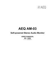
2.1.1. Description of the TH-03.2 front panel and controls.<br />
1 2 3 4 5 6 7 8 9 10 11 12 13 14<br />
1. “LOC/REM” key of LINE 1: allows you to change between local (without pressing) or<br />
remote control (pressed) of line 1. Both modes are exclusive between them.<br />
When remote control is activated, the control keys “XTND”, “WAIT” and “ON AIR” of<br />
that line are no longer active and their functions are managed through remote control<br />
connector (in order to activate any of these functions, only is required to connect to<br />
ground the corresponding remote signal).<br />
2. “XTND” key of LINE 1: allows you to activate the frequency extension function.<br />
The typical telephone circuits have a limited bandwith between 300 and 4000Hz.<br />
Unfortunately, the most part of the voice energy is contained in frequencies lower than<br />
300Hz, which are lost during transmision through the telephone line. For this reason,<br />
the audio signal has the typical telephone sound, being this loss the most representative<br />
aspect.<br />
The frequency extension function allows to transmit the bandwith between 50 and<br />
300Hz through the telephone line. In order to achieve this, the signal sent undergoes a<br />
250Hz frequency shift, improving the quality of the received signal in its lower<br />
frequencies at the expense of the higher band. The transmitted bandwith is, thus,<br />
between 50 and 3750Hz. The lost 250Hz from the higher frequencies are not very<br />
significant, due to the logarithmic nature of the audio frequency response.<br />
The translation of frequencies takes place by encoding the audio signal before it is sent<br />
to the telephone line. Decoding, i.e., the reverse frequency shift, takes place at the<br />
receiving end, that must be done by the appropriate equipment with the frequency<br />
extension function also activated (another TH-03 hybrid, a TLE-02D communications<br />
unit, a TH-03 EX hybrid, an hybrid module of the COURSE system or a FR33 module of<br />
the FORUM console). The decoded signal has the original bandwith (between 50 and<br />
3750Hz) without having suffered any alteration. Thus, greater depth and clarity is<br />
achieved in the voice signal, even in those communications that take place under the<br />
worst conditions.<br />
3. “WAIT” key of LINE 1: allows you to select WAIT mode (on hold) for the incoming call:<br />
line is connected to the digital hybrid and the signal of the corresponding “PROG. IN”<br />
input is sent to the line. The correspondent hears the program but can not take part in it.<br />
When the key is released, the line returns to the telephone set (if not hung up<br />
previously) or the call is disconected (unless the “ON AIR” key is pressed).<br />
4. “ON AIR” key of LINE 1: allows you to select ON AIR mode for the incoming call: line is<br />
connected to the digital hybrid, the signal of the corresponding “PROG. IN” input is sent<br />
to the line and the signal coming from the line is conducted to the corresponding<br />
“PROG. OUT” connector. The correspondent hears the program and takes part in it.<br />
When "ON AIR" and "WAIT" keys are pressed at the same time, ON AIR mode prevails<br />
over WAIT mode.<br />
<strong>AEQ</strong> TH-03<br />
4
5. “LEVEL” VUmeters of LINE 1: a pair of 10 segments precision VUmeters that allows<br />
you to monitor the output (“SND” VUmeter) and input signal (“RCV” VUmeter) of the link<br />
established through line 1.<br />
6. “RING” LED of LINE 1: this LED will blink when an incoming call is detected on line 1.<br />
7. “LOC/REM” key of LINE 2: equivalent functionality that the one described for the line 1<br />
key.<br />
8. “XTND” key of LINE 2: equivalent functionality that the one described for the line 1 key.<br />
9. “WAIT” key of LINE 2: equivalent functionality that the one described for the line 1 key.<br />
10. “ON AIR” key of LINE 2: equivalent functionality that the one described for the line 1<br />
key.<br />
11. “LEVEL” VUmeters of LINE 2: equivalent functionality that the one described for the line<br />
1 VUmeters.<br />
12. “RING” LED of LINE 2: equivalent functionality that the one described for the line 1<br />
LED.<br />
13. “MPX” key: allows you to activate the Multiplex function and perform a cross-talk<br />
between lines 1 and 2 and the unit.<br />
In this working mode, the user of <strong>AEQ</strong> TH-03.2 and two more participants at the ends of<br />
each line can establish a communication in full duplex mode, that is, everyone talks to<br />
everyone and hear each other at all times. When Multiplex function is activated, only the<br />
“PROG. IN” input and “PROG. OUT” output of line 1 are available; the input and output<br />
of line 2 are disabled. Thus, the signal of the line 1 “PROG. IN” input is sent to both<br />
phone lines and the signals coming from both lines are conducted to the line 1 program<br />
output; on the other hand, the signal from the telephone line 1 is also sent to the<br />
telephone line 2 and vice versa.<br />
The operating diagram of this mode is as follows:<br />
14. “POWER” LED: Power On LED indicator.<br />
<strong>AEQ</strong> TH-03<br />
5
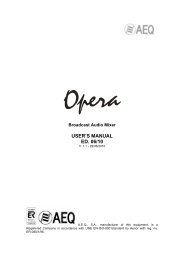
2.1.2. Description of the TH-03.2 rear panel and connections.<br />
1 2 3 4 5 6 7 8 9 10 11 12 13<br />
1. AC power supply connector.<br />
The TH-03 is prepared to operate with supply voltages from 90 to 250 VAC (50/60Hz).<br />
The unit’s mains connector socket has a fuse box, located at the bottom of the plug, and<br />
it’s supplied with a 1A fuse and a spare one.<br />
Note: The power cord of TH-03 is supplied with a European-stardard plug mains<br />
connector. In some countries it may be necessary to replace the plug to fit the current<br />
regulations on them.<br />
2. Power ON/OFF switch.<br />
3. “GPIO” connector for remote control of the unit.<br />
The physical connector used is a DB15 female, with the following pinout:<br />
DB15 connector pinout indentification<br />
- Pin 1: CALL IN LINE 1 - RING 1 - Pin 10: Not connected<br />
- Pin 2: CALL ON WAIT LINE 2 - WAIT 2 - Pin 11: Not connected<br />
- Pin 3: CALL ON AIR LINE 2 - ON AIR 2 - Pin 12: Not connected<br />
- Pin 4: CALL ON WAIT LINE 1 - WAIT 1 - Pin 13: Not connected<br />
- Pin 5: CALL ON AIR LINE 1 - ON AIR 1 - Pin 14: Not connected<br />
- Pin 6: CALL IN LINE 2 - RING 2 - Pin 15: Not connected<br />
- Pin 7: FREQUENCY EXTENSION LINE 1<br />
- Pin 8: FREQUENCY EXTENSION LINE 2<br />
- Pin 9: COMMON GROUND<br />
These connections, when required, must be carried out only by qualified technical<br />
personnel.<br />
In order to control remotely any of the two lines of the unit, you must press previously<br />
the “LOC/REM” key of the corresponding key on the front panel. To activate any of the<br />
available functions the only requirement is to connect the respective remote signal to<br />
ground.<br />
The RING 1 and RING 2 signals allow to recognize the incoming call tone on each<br />
telephone line and can be used to feed two separate LEDs (when the ring signal is<br />
detected on a line, the connected LED lights blinking). The electrical features of this<br />
signal are as follows:<br />
<strong>AEQ</strong> TH-03<br />
6
- When the incoming call tone is connected:<br />
100 ms<br />
20 ms<br />
- When the incoming call tone is disconnected:<br />
0 Volts.<br />
Note: some telephone swithcboards can generate exceptionally low incoming call<br />
signals, much lower than 75 VRMS, which the equipment will not detect. In this case,<br />
please contact our Technical Service, which will give you advice about the required<br />
modification for solving the problem.<br />
4. “TEL. SET” connector (RJ11 type) for line 2 telephone set. Allows you to connect an<br />
external telephone terminal in order to do the dial or take a call.<br />
5. “TEL. LINE” connector (RJ11 type) for telephone line 2.<br />
6. “PROG. OUT” connector (XLR-3p male type) for analogue or digital output (see section<br />
3.1.1) of the line 2 program. This output is disabled when Multiplex function is activated<br />
(see section 2.1.1). The connector pinout is as follows:<br />
Pin 1: Ground<br />
Pin 2: Output +<br />
Pin 3: Output –<br />
When using the digital option, only the L channel of the stereo digital output will carry<br />
audio signal.<br />
7. LED indicator for optional digital AES/EBU input/output board installed and operative for<br />
line 2.<br />
8. “PROG. IN” connector (XLR-3p female type) for analogue or digital input (see section<br />
3.1.1) of the line 2 program. This input is disabled when Multiplex function is activated<br />
(see section 2.1.1). The connector pinout is as follows:<br />
Pin 1: Ground<br />
Pin 2: Input +<br />
Pin 3: Input –<br />
When using the digital option, only the L channel of the stereo digital input will be sent<br />
to the line.<br />
9. “TEL. SET” connector (RJ11 type) for line 1 telephone set. Allows you to connect an<br />
external telephone terminal in order to do the dial or take a call.<br />
10. “TEL. LINE” connector (RJ11 type) for telephone line 1.<br />
<strong>AEQ</strong> TH-03<br />
7
11. “PROG. OUT” connector (XLR-3p male type) for analogue or digital output (see section<br />
3.1.1) of the line 1 program (or both lines in Multiplex mode). The connector pinout is as<br />
follows:<br />
Pin 1: Ground<br />
Pin 2: Output +<br />
Pin 3: Output –<br />
When using the digital option, only the L channel of the stereo digital output will carry<br />
audio signal.<br />
12. LED indicator for optional digital AES/EBU input/output board installed and operative for<br />
line 1.<br />
13. “PROG. IN” connector (XLR-3p female type) for analogue or digital input (see section<br />
3.1.1) of the line 1 program (or both lines in Multiplex mode). The connector pinout is as<br />
follows:<br />
Pin 1: Ground<br />
Pin 2: Input +<br />
Pin 3: Input –<br />
When using the digital option, only the L channel of the stereo digital input will be sent<br />
to the line.<br />
<strong>AEQ</strong> TH-03<br />
8
2.2. Physical description of the 1 line hybrid: TH-03.1.<br />
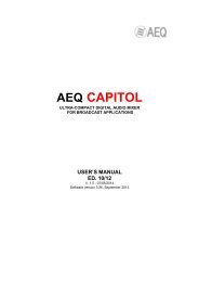
2.2.1. Description of the TH-03.1 front panel and controls.<br />
1 2 3 4 5 6 7<br />
1. “LOC/REM” key: allows you to change between local (without pressing) or remote<br />
control (pressed). Both modes are exclusive between them.<br />
When remote control is activated, the control keys “XTND”, “WAIT” and “ON AIR” are<br />
no longer active and their functions are managed through remote control connector (in<br />
order to activate any of these functions, only is required to connect to ground the<br />
corresponding remote signal).<br />
2. “XTND” key of LINE 1: allows you to activate the frequency extension function.<br />
The typical telephone circuits have a limited bandwith between 300 and 4000Hz.<br />
Unfortunately, the most part of the voice energy is contained in frequencies lower than<br />
300Hz, which are lost during transmision through the telephone line. For this reason,<br />
the audio signal has the typical telephone sound, being this loss the most representative<br />
aspect.<br />
The frequency extension function allows to transmit the bandwith between 50 and<br />
300Hz through the telephone line. In order to achieve this, the signal sent undergoes a<br />
250Hz frequency shift, improving the quality of the received signal in its lower<br />
frequencies at the expense of the higher band. The transmitted bandwith is, thus,<br />
between 50 and 3750Hz. The lost 250Hz from the higher frequencies are not very<br />
significant, due to the logarithmic nature of the audio frequency response.<br />
The translation of frequencies takes place by encoding the audio signal before it is sent<br />
to the telephone line. Decoding, i.e., the reverse frequency shift, takes place at the<br />
receiving end, that must be done by the appropriate equipment with the frequency<br />
extension function also activated (another TH-03 hybrid, a TLE-02D communications<br />
unit, a TH-03 EX hybrid, an hybrid module of the COURSE system or a FR33 module of<br />
the FORUM console). The decoded signal has the original bandwith (between 50 and<br />
3750Hz) without having suffered any alteration. Thus, greater depth and clarity is<br />
achieved in the voice signal, even in those communications that take place under the<br />
worst conditions.<br />
3. “WAIT” key: allows you to select WAIT mode (on hold) for the incoming call: line is<br />
connected to the digital hybrid and the signal of the corresponding “PROG. IN” input is<br />
sent to the line. The correspondent hears the program but can not take part in it. When<br />
the key is released, the line returns to the telephone set (if not hung up previously) or<br />
the call is disconected (unless the “ON AIR” key is pressed)<br />
4. “ON AIR” key: allows you to select ON AIR mode for the incoming call: line is connected<br />
to the digital hybrid, the signal of the corresponding “PROG. IN” input is sent to the line<br />
and the signal coming from the line is conducted to the corresponding “PROG. OUT”<br />
connector. The correspondent hears the program and takes part in it. When "ON AIR"<br />
and "WAIT" keys are pressed at the same time, ON AIR mode prevails over WAIT<br />
mode.<br />
5. “LEVEL” VUmeters: a pair of 10 segments precision VUmeters that allows you to<br />
monitor the output (“SND” VUmeter) and input signal (“RCV” VUmeter) of the<br />
established link.<br />
<strong>AEQ</strong> TH-03<br />
9
6. “RING” LED: this LED will blink when an incoming call is detected.<br />
7. “POWER” LED: Power On LED indicator.<br />
2.2.2. Description of the TH-03.1 rear panel and connections.<br />
1 2 3 4 5 6 7 8<br />
1. AC power supply connector.<br />
The TH-03 is prepared to operate with supply voltages from 90 to 250 VAC (50/60Hz).<br />
The unit’s mains connector socket has a fuse box, located at the bottom of the plug, and<br />
it’s supplied with a 1A fuse and a spare one.<br />
Note: The power cord of TH-03 is supplied with a European-stardard plug mains<br />
connector. In some countries it may be necessary to replace the plug to fit the current<br />
regulations on them.<br />
2. Power ON/OFF switch.<br />
3. “GPIO” connector for remote control of the unit.<br />
The physical connector used is a DB15 female, with the following pinout:<br />
DB15 connector pinout indentification<br />
- Pin 1: CALL IN LINE - RING - Pin 10: Not connected<br />
- Pin 2: Not connected - Pin 11: Not connected<br />
- Pin 3: Not connected - Pin 12: Not connected<br />
- Pin 4: CALL ON WAIT - Pin 13: Not connected<br />
- Pin 5: CALL ON AIR - Pin 14: Not connected<br />
- Pin 6: Not connected - Pin 15: Not connected<br />
- Pin 7: FREQUENCY EXTENSION<br />
- Pin 8: Not connected<br />
- Pin 9: COMMON GROUND<br />
These connections, when required, must be carried out only by qualified technical<br />
personnel.<br />
In order to control remotely any of the two lines of the unit, you must press previously<br />
the “LOC/REM” key of the corresponding key on the front panel. To activate any of the<br />
available functions the only requirement is to connect the respective remote signal to<br />
ground.<br />
The RING signal allows to recognize the incoming call tone on the telephone line and<br />
can be used to feed a LED (when the ring signal is detected on the line, the connected<br />
LED lights blinking). The electrical features of this signal are as follows:<br />
<strong>AEQ</strong> TH-03<br />
10
- When the incoming call tone is connected:<br />
100 ms<br />
20 ms<br />
- When the incoming call tone is disconnected:<br />
0 Volts.<br />
Note: some telephone swithcboards can generate exceptionally low incoming call<br />
signals, much lower than 75 VRMS, which the equipment will not detect. In this case,<br />
please contact our Technical Service, which will give you advice about the required<br />
modification for solving the problem.<br />
4. “TEL. SET” connector (RJ11 type) for telephone set. Allows you to connect an external<br />
telephone terminal in order to do the dial or take a call.<br />
5. “TEL. LINE” connector (RJ11 type) for telephone line.<br />
6. “PROG. OUT” connector (XLR-3p male type) for program analogue or digital output<br />
(see section 3.1.1). The connector pinout is as follows:<br />
Pin 1: Ground<br />
Pin 2: Output +<br />
Pin 3: Output –<br />
When using the digital option, only the L channel of the stereo digital output will carry<br />
audio signal.<br />
7. LED indicator for optional digital AES/EBU input/output board installed and operative.<br />
8. “PROG. IN” connector (XLR-3p female type) for program analogue or digital input (see<br />
section 3.1.1). The connector pinout is as follows:<br />
Pin 1: Ground<br />
Pin 2: Input +<br />
Pin 3: Input –<br />
When using the digital option, only the L channel of the stereo digital input will be sent<br />
to the line.<br />
<strong>AEQ</strong> TH-03<br />
11
3. AUDIO CONNECTIONS.<br />
3.1. General.<br />
The audio connections of the TH-03 have been made in accordance to the<br />
recommendations of AES 14-1.992 (ANSIS 4.48-1.992). This recommendation is based upon<br />
the IEC 268-12 of 1.987 (Audio Systems Equipment Part 12, Connector application for Radio<br />
Broadcasting and similar use).<br />
Make sure that the audio cables that you are connecting to the equipment follow this standard.<br />
Otherwise, they have to be replaced or modified, since they can cause problems in the phase of<br />
the audio signal.<br />
3.1.1. Connection of audio inputs and outputs.<br />
The TH-03 can work with analogue or digital AES/EBU signals. These last ones are optionals<br />
and use the same XLR connectors than the analogue ones. Therefore, in the case of the TH-<br />
03.1 it is possible to use only one of the two types of signal; in the case of the TH-03.2 one line<br />
can be configurated with analog input/output and the other line with digital input/output, or both<br />
of them with only analogue or only digital inputs/outputs.<br />
The TH-03 is provided by default (unless specific request) with analogue inputs and outputs,<br />
allthough these can be converted into digital by means of the insertion of an additional board (or<br />
two, in the case of the TH-03.2) in the main base board and changing some PDP's on that<br />
board. This operation requires opening the unit, so that must be done by specialized personnel<br />
and the equipment must be disconnected from electrical power and telephone line.<br />
In order to find out if the equipment is configured with digital inputs and outputs, it has a LED<br />
indicator (two LEDs in the case of the TH-03.2) on the rear part, between the “PROG.OUT” and<br />
“PROG. IN” connectors (see sections 2.1.2 and 2.2.2).<br />
If you need to convert the TH-03 from analogue to digital, please consult the Technical<br />
Assistance Service of <strong>AEQ</strong>.<br />
4. CONTROL FUNCTIONS.<br />
The TH-03 has a number of control functions to select the operating mode of each connected<br />
line. All functions are independent for each line.<br />
In local mode, the control functions are activated/desactivated by means of the keys on the<br />
front panel (see sections 2.1.1 and 2.2.1). In remote mode, those functions can be<br />
activated/desactivated by remote control through the corresponding "GPIO" connector (see<br />
sections 2.1.2 and 2.2.2). You can select the operating mode by pressing the "LOC/REM" key<br />
on the front panel. Both modes are exclusive between them.<br />
<strong>AEQ</strong> TH-03<br />
12
5. TECHNICAL SPECIFICATIONS.*<br />
Audio Inputs and Outputs<br />
Analog program input<br />
Analog program output<br />
XLR female<br />
Input impedance: >6KΩ<br />
Electronic balancing<br />
Nominal input level: 0dBm<br />
XLR male<br />
Electronic balancing<br />
Nominal output level: 0dBm<br />
XLR female<br />
Nominal input level: -22dBFS<br />
XLR male<br />
Nominal output level: -22dBFS<br />
Digital program input<br />
(optional by means of additional board)<br />
Digital program output<br />
(optional by means of additional board)<br />
Telephone line interface<br />
Input/output<br />
By transformer<br />
Impedance: 600Ω<br />
Bandwith<br />
With frequency extension desactivated:<br />
300 - 4000Hz, +/-1dB<br />
With frequency extension activated:<br />
50 - 3750Hz, +/-1dB<br />
THD+N Distortion Line:
6. A.E.Q. WARRANTY.<br />
<strong>AEQ</strong> guarantees that this product has been designed and manufactured under a certified<br />
Quality Assurance System and according to the UNE166002 Standard. <strong>AEQ</strong> therefore<br />
Guarantees that the necessary test protocols to assure the proper operation and the specified<br />
technical characteristics of the product have been followed and accomplished.<br />
This includes that the general protocols for design and production and the particular ones for<br />
this product are conveniently documented.<br />
1.- The present guarantee does not exclude or limit in any way any legally recognized right of<br />
the client.<br />
2.- The period of guarantee is defined to be twelve natural months starting from the date of<br />
purchase of the product by the first client.<br />
To be able to apply to the established in this guarantee, it is compulsory condition to inform the<br />
authorized distributor or –to its effect- an <strong>AEQ</strong> Sales office or the Technical Service of <strong>AEQ</strong><br />
within thirty days of the appearance of the defect and within the period of guarantee, as well as<br />
to facilitate a copy of the purchase invoice and serial number of the product.<br />
It will be equally necessary the previous and expressed conformity from the <strong>AEQ</strong> Technical<br />
Service for the shipment to <strong>AEQ</strong> of products for their repair or substitution in application of the<br />
present guarantee.<br />
In consequence, return of equipment that does not comply with these conditions will not be<br />
accepted.<br />
3.- <strong>AEQ</strong> will at its own cost repair the faulty product once returned, including the necessary<br />
labour to carry out such repair, whenever the failure is caused by defects of the materials,<br />
design or workmanship. The repair will be carried out in any of the <strong>AEQ</strong> authorized Technical<br />
Service Center. This guarantee does not include the freight charges of the product to or from<br />
such Authorized Technical Service Center.<br />
4.- No Extension of the Guarantee Period for repaired product shall be applied. Nor shall a<br />
Substituted Products in application of this Guarantee be subject to Guarantee Period Extension.<br />
5.- The present guarantee will not be applicable in the following situations:<br />
improper use or Contrary use of the product as per the User or Instruction <strong>Manual</strong>; violent<br />
manipulation; exhibition to humidity or extreme thermal or environmental conditions or sudden<br />
changes of such conditions; electrical discharges or lightning; oxidation; modifications or not<br />
authorized connections; repairs or non-authorized disassembly of the product; spill of liquids or<br />
chemical products.<br />
6.- Under no circumstances, whether based upon this Limited Guarantee or otherwise, shall<br />
<strong>AEQ</strong>, S.A. be liable for incidental, special, or consequential damages derived from the use or<br />
from the impossibility of using the product.<br />
<strong>AEQ</strong> shall not be liable for loss of information in the disks or data support that have been altered<br />
or found to be inexact, neither for any accidental damage caused by the user or other persons<br />
manipulating the product.<br />
<strong>AEQ</strong> TH-03<br />
14