Manual (78°C) - Laddomat
Manual (78°C) - Laddomat
Manual (78°C) - Laddomat

Create successful ePaper yourself
Turn your PDF publications into a flip-book with our unique Google optimized e-Paper software.
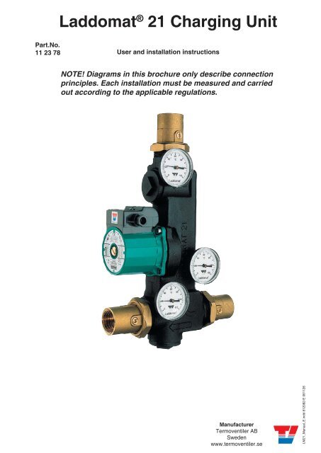
<strong>Laddomat</strong> ® 21 Charging Unit<br />
Part.No.<br />
11 23 78<br />
User and installation instructions<br />
NOTE! Diagrams in this brochure only describe connection<br />
principles. Each installation must be measured and carried<br />
out according to the applicable regulations.<br />
Manufacturer<br />
Termoventiler AB<br />
Sweden<br />
www.termoventiler.se<br />
LM21_<strong>Manual</strong>_E.indd 812082-E 061128<br />
1
The <strong>Laddomat</strong> 21 is designed to...<br />
...allow the boiler to reach a high working temperature<br />
soon after firing.<br />
...to heat the cold tank water in the bottom of the boiler<br />
so that the boiler does not rust away through corrosion.<br />
…charge the tank with water at a high and even temperature<br />
and low flow, to ensure optimal separation in the<br />
tank.<br />
…transfer the residual heat in the boiler to the tank after<br />
the fire has gone out.<br />
…in the event of a power cut stopping the pump, transfer<br />
the heat in the boiler to the tank through self-circulation.<br />
Operation<br />
The <strong>Laddomat</strong> 21 functions fully automatically provided<br />
that pump start and stop is automated. See page 4.<br />
The settings described in this User manual are normally<br />
made only once.<br />
The <strong>Laddomat</strong> requires no special supervision or service.<br />
* = L = L A<br />
" 1/<br />
1 JA C H= JA @<br />
JD A H = L = L A<br />
1 JA C H= JA @ <br />
F K F<br />
9 E <br />
4 5 # ` $ !<br />
6 D A H A JA H<br />
+ A ? JE <br />
J > JJ <br />
B> EA H<br />
* = L = L A<br />
" 1/<br />
) K J = JE? L = L A <br />
B HI A B? EH? K = JE <br />
E A L A J B= F M A H? K J<br />
+ A ? JE J J F B> EA H<br />
6 D A H A JA H<br />
. EA H? = F<br />
6 D A H A JA H<br />
* = L = L A<br />
" 1/<br />
, EHJF ? A J<br />
- = I O J ? A = <br />
2 HA L A JI F A H= JE C<br />
E JA HHK F JE I<br />
! # "<br />
+ A ? JE <br />
J J= <br />
# "<br />
The main parts of a wood burning set-up<br />
5 = BA JO L = L A<br />
0 JM = JA H<br />
+ @ M = JA H<br />
EN A HL = L A<br />
- N F<br />
L A I I A <br />
* O F = I I <br />
L = L A <br />
= K J = JE?<br />
4 I A I H<br />
. M I A I H<br />
4 = @ E= J H<br />
4 = @ E= J HF K F<br />
* O F = I I L = L A<br />
+ L A H<br />
5 F HE C<br />
2 K C A H<br />
6 D A H I J= J<br />
? = HJHE@ C A<br />
. K A<br />
JD A H I J= J<br />
- A ? JHE?<br />
D A = JA H<br />
, A I JE?<br />
M = JA H<br />
D A = JA H<br />
* EA H<br />
. EE C L = L A<br />
5 J H= C A J= <br />
+ D A ? L = L A <br />
M = I D A H<br />
= @ @ = J <br />
+ L A H<br />
0 @ A H<br />
5 F HE C<br />
2
Description of functions<br />
Starting the boiler<br />
To achieve a high level of efficiency and low emissions of unburned substances, it is<br />
important that the boiler reaches working temperature quickly.<br />
This is achieved by the circulation pump starting as firing starts. This prevents cold<br />
water from the bottom of the tank cooling the boiler unnecessarily, through selfcirculation.<br />
The circulation pump can be started in three different ways, see page 4.<br />
Firing has started in the illustration to the right. The pump has started. The thermostat<br />
cartidge has not started to open yet.<br />
The valve plate of the self-circulating valve is kept closed by the water pressure from the<br />
circulation pump.<br />
Start up<br />
Operating phase<br />
The boiler has reached operating temperature. The thermostat cartridge has opened and<br />
mixes in cold water from the tank.<br />
The mixed water entering the bottom of the boiler has a temperature of about 5–20°C<br />
below the opening temperature of the thermostat cartridge. The higher the output of<br />
the boiler and the higher the temperature of the water exiting the boiler, the more cold<br />
water is mixed in from the bottom of the tank.<br />
This is the same characteristic that allows <strong>Laddomat</strong> 21 to separate effectively = charging<br />
to the tank under all different operating conditions in different boilers.<br />
Final phase<br />
During the final phase of charging the by-pass port in <strong>Laddomat</strong> 21 is completely closed<br />
to the top of the boiler. All water is routed to the tank which becomes fully charged.<br />
Self circulation when the burner has stopped<br />
If a flue thermostat or similar equipment is installed, it will stop the pump immediately<br />
after the fire goes out.<br />
The advantage of stopping the pump quickly after the fire goes out is that the cool<br />
return water from the radiator circuit flows into the bottom of the boiler through selfcirculation.<br />
The stored heat in the boiler is then transferred to the top of the tank, and<br />
the house then benefits from it.<br />
Stopping the pump when heating ceases, either manually or automatically, is important<br />
for one further reason. The hot water in the tank will otherwise be mixed with cold<br />
radiator water down to the closing temperature of the thermostat cartridge. If the tank<br />
is heated to 90°C and the thermostat cartridge closes at 75° the whole tank falls to this<br />
temperature if the pump is not switched off .<br />
Operating phase<br />
Final phase<br />
Self circulation in event of a power cut<br />
If a power cut occurs during firing, self-circulation starts automatically through the<br />
easily opened check valve, on the condition that the water in the tank is colder than the<br />
water in the boiler.<br />
The self-circulation power is created by the weight difference between lighter hot water<br />
and heavier cold water. If the tank is completely heated all the way to the bottom, selfcirculation<br />
will be limited, and the boiler could still hit boiling point.<br />
This boiling can be stopped by feeding a small quantity of cold water directly into the<br />
bottom of the boiler through the system filling tap.<br />
In the event of a sustained power cut, the whole house can be heated through selfcirculation,<br />
if the pipe-runs and dimensions are suitable.<br />
The firing should be matched to the output which can be transferred to the storage<br />
tank through self-circulation.<br />
Self-circulation<br />
3
Installation<br />
Dimensioning<br />
Generous pipe dimensions and short lengths guarantee<br />
operating reliability, even when the demand for heat is<br />
high. This also allows effective self-circulation in the event<br />
of power cuts.<br />
Pipe dimensions at a maximum boiler to tank distance of<br />
3 m.<br />
Boilers up to:<br />
35 kW min. 28 cu pipe or R25<br />
50 kW min. 35 cu pipe or R32<br />
80 kW min. 42 cu pipe or R40<br />
The dimensions must be increased for longer pipes.<br />
If there are special requirements for self-circulation, the<br />
pipes must be dimensioned accordingly.<br />
Connection<br />
The <strong>Laddomat</strong> ® 21 must always be connected in the<br />
upright position as shown in the diagrams.<br />
Position <strong>Laddomat</strong> 21 close to the boiler and on the level of<br />
the boilers bottom outlet, no higher than approximately 20<br />
cm above the floor on which the boiler stands.<br />
Pipe-runs must be as short as possible and have the minimum<br />
number of bends. Make sure that all air pockets are<br />
eliminated.<br />
The diameter of the pipe from the top of the boiler to the<br />
T-pipe and down to the <strong>Laddomat</strong> 21 must be as large<br />
as possible. This gives low water-velocity, and allows air<br />
released in the boiler to separate out in the expansion<br />
chamber or the vent.<br />
The location of the filler serves two purposes. Firstly, in<br />
filling the system, both the boiler and the tank are filled<br />
through the bottom connections to facilitate the venting<br />
of all air. Secondly, boiling can be prevented, by adding<br />
cold water. Connect a union coupling between the filler<br />
tap and the outlet to make future servicing easier.<br />
Bleeding<br />
9 out of 10 operating interruptions are due to air in the<br />
charging circuit preventing circulation.<br />
For optimum operation, pipe-runs should be arranged so<br />
as to allow all air to escape from the system.<br />
High points in the pipe-runs should be avoided, but, if<br />
this is not possible, they should be fitted with vents of the<br />
air gauge type. NOTE! Not automatic air vents.<br />
There are substantial variations in the ability of different<br />
waters to hold air. This air is released in the boiler when<br />
the water is heated. Think of the amount of air bubbles<br />
which occur when heating water in a saucepan.<br />
Starting and stopping the charging<br />
pump<br />
It is important to start the pump as soon as the firing<br />
starts to ensure that the boiler heats up rapidly.<br />
Stopping the pump quickly when the fire has gone out<br />
will make the hot water self-circulate from the top of the<br />
boiler to the storage tank.<br />
Some boilers have integrated thermostats to control the<br />
pump. Check that this control system operates correctly<br />
with the boiler.<br />
. K A JD A H I J= J<br />
1BBEJJA @ M = JA H<br />
JD A H I J= JJ<br />
> A ? A ? JA @<br />
E F = H= A <br />
* EA H<br />
NOTE Not included in delivery<br />
Setting the pump speed<br />
<br />
<br />
5 J L A F EF A<br />
* K ><br />
2 K F<br />
5 M EJ? D<br />
<strong>Laddomat</strong> Flue thermostat<br />
Part.no.131001<br />
The speed control for the circulation pump must be in<br />
position 3. Position 2 is only used for boilers that produce<br />
less than 25 kW.<br />
Position 1 must not be used because the lower starting<br />
torque at this speed cannot guarantee a good start.<br />
If higher or lower charging temperatures than the standard<br />
thermostat cartridge can provide are required one<br />
can easily change to a thermostat which opens at 63°, 72°,<br />
78°, 83° or 87°C.<br />
4
Service<br />
Before carrying out any servicing work, close the three<br />
shut-offs by setting the screwdriver slot on the valves at<br />
right angles to the direction of the pipe. This makes it<br />
easy to access the pump, thermal valve and check valve for<br />
service.<br />
If operating interruptions still occur, even though the system<br />
has been bled, there may be dirt such as lint, tape or<br />
thread swarf stuck in the coupling. Disassemble and clean.<br />
Clean all sealing surfaces when reassembling:<br />
1. The thermal valve<br />
2. The self-circulation valve<br />
3. The pump impeller<br />
In some installations, there are problems with extremely<br />
high levels of contaminants. These can form deposits<br />
inside the pump, which may result in stoppages.<br />
Stoppages can be avoided if the pump is disassembled and<br />
the rotor and pump housing are cleaned in accordance<br />
with the manufacturer’s instructions.<br />
Expansion vessel<br />
If stoppages due to air continue to occur, despite the fact<br />
that the system has been installed in accordance with the<br />
instructions provided, check that:<br />
The expansion vessel is sufficiently large, at least 5 % of<br />
the total volume when the tank is open. Operating pressure<br />
must always be at least 2 metre water column = 0.2<br />
bar more than the height difference from the pressure<br />
gauge to the upper edge of the highest radiator.<br />
If a pressure vessel is installed, this must be at least<br />
10–20% of the total volume. Each installation must be<br />
specially dimensioned in accordance with the<br />
manufacturer’s instructions.<br />
Check that the operating pressure, where the installation<br />
is cold, is never lower than the height difference between<br />
the pressure gauge and the highest radiator + 2 meter<br />
water column (mwc).<br />
Example: Height from centre of pressure gauge to upper<br />
edge of highest radiator = 3 m.<br />
Lowest operating pressure = 3 + 2 mwc = 5 mwc = 0.5 bar<br />
Thermostat cartridge<br />
The thermostat cartridge is available as a spare part, and<br />
may need to be replaced if it is regularly exposed to<br />
temperatures close to, or above, boiling point.<br />
The number is engraved on the cartridge.<br />
No.<br />
Opening temperature<br />
5839 63°C<br />
8719 72°C<br />
1456 78°C<br />
1467 83°C<br />
8222 87°C<br />
Technical data<br />
Pump:<br />
Wilo RS25-6-3<br />
Connections:<br />
R32 (3 pcs)<br />
Opening temperature: 63, 72, 78, 83 or 87°C<br />
Kv value: 14<br />
Boiler output:<br />
max 80 kW<br />
Radiator system<br />
To make the maximum use of the storage tank, it is very<br />
important that the radiator system is fitted with:<br />
1. Automatic by-pass control<br />
2. Thermostatic valves with integrated pressure reduction<br />
devices, which are set to suit the radiator size.<br />
Both measures are intended to reduce the flow and so<br />
reduce the return temperature. Without raising the<br />
delivery temperature. The lower the return<br />
temperature, the longer the heat in the tank lasts.<br />
+ L A H<br />
5 F HE C 2 K C A H<br />
6 D A H I J= J<br />
HE C<br />
HE C<br />
5
Connecting to a tank<br />
1. The pipe-runs shown on the diagram are optimised to<br />
reduce air-related operating interruptions to a<br />
minimum.<br />
2. The hot water pipe to the by-pass valve can be<br />
connected in two ways.<br />
a) Approx 30 cm from the top of the tank to prioritise<br />
domestic hot water.<br />
b) On the charge line connection<br />
to the tank to prioritise<br />
heating. The connection<br />
is directed downwards<br />
to prevent air rising to the<br />
radiators.<br />
6 D A = @ @ = J <br />
? = A = I EO > A <br />
HA L A HI A @ B HHEC D J<br />
D = @ K JE C <br />
K I J L A JD A <br />
JD A H A JA HI J <br />
JD A JD A HI E@ A <br />
) , , ) 6 <br />
5 = BA JO L = L A<br />
. K A<br />
JD A H I J= J<br />
* EA H<br />
0 JM = JA H<br />
+ @ M = JA H<br />
EN A HL = L A<br />
. EE C L = L A<br />
- N F<br />
L A I I A <br />
* O F = I I <br />
L = L A <br />
= K J = JE?<br />
- A ? JHE?<br />
D A = JA H<br />
, A I JE?<br />
M = JA H<br />
D A = JA H<br />
5 J H= C A J= <br />
4 I A I H<br />
. M I A I H<br />
4 = @ E= J H<br />
4 = @ E= J HF K F<br />
* O F = I I L = L A<br />
Connecting 2 – 3 tanks<br />
The tanks must be located up against each other, and as<br />
close as possible to the boiler. The pipe-runs from the<br />
bottom of the tanks are always laid close to the floor.<br />
It is important that the flow to the tanks during charging<br />
and discharging is distributed equally. If the system is<br />
connected wrongly, then charging will be cut off when<br />
tank number 1 is full of hot water which will reach the<br />
boiler before the other tanks are completely filled. Tanks 2<br />
and 3 will be virtually unused.<br />
If the system is connected wrongly the warm water and<br />
the heat will run out earlier than estimated after the<br />
burner has stopped, since tank 1 will cool down more<br />
quickly than the others.<br />
If these requirements cannot be met, there are other<br />
connection options.<br />
Equal pipe lengths<br />
To achieve equal resistance, it is essential to use approximately<br />
the same pipe-lengths to the tanks, this is achieved<br />
by:<br />
1. Connecting the charging circuit diagonally, A–A<br />
2. Connecting the radiator circuit diagonally, B–B.<br />
In addition, the dimension of the pipes between the<br />
tanks must be large enough to facilitate self-circulation<br />
between the tanks. Alternatively, locate the hot<br />
water heater in the centre. It is an advantage if the<br />
tanks are connected together in the centre, to further<br />
distribute the heat.<br />
) JA H = JEL A <br />
? = JE B H<br />
A N F = I E <br />
L A I I A <br />
* EA H<br />
) , , ) 6 <br />
0 J<br />
M = JA H<br />
EN E C<br />
L = L A<br />
= @ @ = J <br />
NOTE If the radiator<br />
is connected in<br />
this way there<br />
is a large risk of<br />
heat retention in<br />
the boiler and/or<br />
reduced heat to the<br />
radiator circuit.<br />
+ @<br />
M = JA H<br />
6 = <br />
The pipe to the<br />
bottom of the tank<br />
must not be routed<br />
through the roof.<br />
4 = @ E= J H<br />
- N F<br />
L A I I A <br />
Connecting the by-pass valve<br />
The hot water port is connected at B, which prioritises<br />
hot water, or at B1, which prioritises heating.<br />
6 F EF A H<br />
= HC A HB H> A I J<br />
L A JE C BK ? JE <br />
5 = BA JO <br />
L = L A<br />
)<br />
* <br />
*<br />
6 = <br />
6 = 6 = !<br />
Electrical immersion heater operation<br />
When operating solely on the electrical immersion<br />
heater, it is an advantage only to heat the first tank to<br />
prevent heat loss. Shut off the other tanks using the<br />
valves at the bottom of each tank.<br />
* EA H<br />
= @ @ = J <br />
. EA HL = L A<br />
- A ? JHE? = E A HI E <br />
D A = JA H<br />
)<br />
*<br />
6
Connection suggestions<br />
1 I J= = JE M EJD F A A N F = I E L A I I A <br />
A L A <br />
F EF A<br />
5 = BA JO E A E , #<br />
<br />
4 = @ E= J H<br />
- N F = I E <br />
F EF A <br />
, <br />
6 = <br />
* EA H<br />
) , , ) 6 <br />
+ @ M = JA H<br />
BEI JD A <br />
A N F = I E <br />
L A I I A @ K HE C <br />
BEHE C A I I <br />
D A = J I I<br />
) , , ) 6 <br />
Bottom connection of the expansion vessel gives reduced heat losses<br />
NOTE See information on page 5 about the expansion vessel<br />
+ A ? JE C = F HA I I K HEI A @ A N F = I E L A I I A <br />
) JA H = JEL A E I J= = JE M EJD F A A N F = I E L A I I A <br />
9 D A ? A ? JE C <br />
JD A A N F = I E L A I I A <br />
= M = O I ? A ? J= <br />
F HA I I K HA C = K C A<br />
) K J = JE?<br />
L A J<br />
4 = @ E= J H<br />
<br />
4 = @ E= J H<br />
6 = <br />
+ @ M = JA HBEI <br />
JD A A N F = I E <br />
L A I I A @ K HE C <br />
BEHE C A I I <br />
D A = J I I<br />
5 J H= C A J= <br />
* EA H<br />
) , , ) 6 <br />
* EA H<br />
= @ @ = J <br />
5 D K J BB@ H= E E C B H<br />
I E F EBEA @ ? D A ? I B<br />
F HA F HA I I K HA<br />
) , , ) 6 <br />
= @ @ = J <br />
7
On delivery, the <strong>Laddomat</strong> 21 is fitted<br />
with a number 1456 thermostat,<br />
which opens at 78°C.<br />
A number 8719 thermostat, which<br />
opens at 72°C, is included but not<br />
fitted.<br />
The most common reason for operational stoppages when<br />
starting up new installations is that air-bubbles prevent<br />
circulation at high temperatures.<br />
In all new installations, there are varying amounts of air<br />
trapped in the fresh water. This air is released as the water<br />
is heated. The warmer the water, the more air is released.<br />
The released air collects in large bubbles, which can prevent<br />
circulation if they reach the pump.<br />
At lower temperatures, the air is released more slowly, and<br />
it can rise up and be vented away through the expansion<br />
vessel and vent, if fitted.<br />
Therefore a thermostat which opens at 72°C is also<br />
supplied.<br />
Use this in installations that are having start-up problems.<br />
When all the water is free of air after being heated to a<br />
temperature of 85–95°C a number of times, it is better to<br />
use the thermostat which opens at 78°C.<br />
Higher charging temperatures give more stored heat. With<br />
the 78°C thermostat, the losses in the boiler when the fire<br />
goes out are lower, as the link between the boiler and the<br />
tank is closed earlier than with the 72°C thermostat.<br />
In the majority of installations, the 78°C thermostat gives<br />
the best results. With high output/low water-volume boilers<br />
and in installations with long pipe-runs and/or fragile<br />
pipes, the system will function best with a number 8719<br />
thermostat, which opens at 72°C.<br />
+ L A H<br />
5 F HE C 2 K C A H<br />
6 D A H I J= J<br />
Instructions for replacing the<br />
thermostat in the <strong>Laddomat</strong> 21<br />
Check that the pump is switched off.<br />
Close the three shut-offs.<br />
Unscrew the cover above the pump<br />
Remove the cover with the spring, plunger and thermostat<br />
from the <strong>Laddomat</strong> 21.<br />
The thermostat is held in place on the plunger by an O-<br />
ring.<br />
Press the thermostat gently out of the plunger.<br />
Push the new thermostat into the plunger.<br />
Reinstall the cover with the spring, plunger and thermostat.<br />
Open the shut-off valves.<br />
Wait a few minutes before starting the pump to allow any<br />
air to rise and escape from the system.<br />
The installation is now ready for use.<br />
HE C<br />
HE C<br />
8