SCANTER 4000/4100 - terma
SCANTER 4000/4100 - terma
SCANTER 4000/4100 - terma

You also want an ePaper? Increase the reach of your titles
YUMPU automatically turns print PDFs into web optimized ePapers that Google loves.
Class: RPT<br />
Doc. no: 264001-RE<br />
Rev: A<br />
Date: 2007-04-25<br />
Approved by: JCP<br />
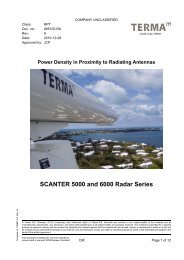
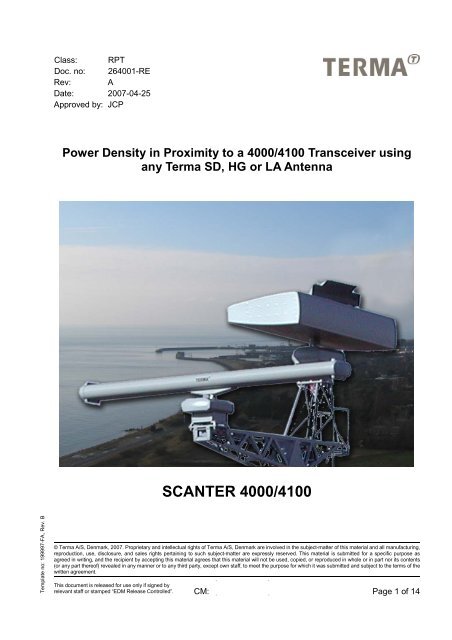
Power Density in Proximity to a <strong>4000</strong>/<strong>4100</strong> Transceiver using<br />
any Terma SD, HG or LA Antenna<br />
<strong>SCANTER</strong> <strong>4000</strong>/<strong>4100</strong><br />
Template no: 199997-FA, Rev. B<br />
© Terma A/S, Denmark, 2007. Proprietary and intellectual rights of Terma A/S, Denmark are involved in the subject-matter of this material and all manufacturing,<br />
reproduction, use, disclosure, and sales rights pertaining to such subject-matter are expressly reserved. This material is submitted for a specific purpose as<br />
agreed in writing, and the recipient by accepting this material agrees that this material will not be used, copied, or reproduced in whole or in part nor its contents<br />
(or any part thereof) revealed in any manner or to any third party, except own staff, to meet the purpose for which it was submitted and subject to the terms of the<br />
written agreement.<br />
. .<br />
This document is released for use only if signed by<br />
relevant staff or stamped “EDM Release Controlled”.<br />
CM:<br />
. . Page 1 of 14
Power Density in Proximity to a <strong>4000</strong>/<strong>4100</strong> Transceiver using any Terma SD, HG or LA<br />
Antenna<br />
Doc. no: 264001-RE, Rev: A<br />
Page 2 of 14<br />
Record of Changes<br />
CR/CO Description Rev Date<br />
First release A See first page<br />
The use and/or disclosure, etc. of the contents of this document (or any part thereof) is subject to the restrictions referenced on the front page.
Power Density in Proximity to a <strong>4000</strong>/<strong>4100</strong> Transceiver using any Terma SD, HG or LA<br />
Antenna<br />
Doc. no: 264001-RE, Rev: A<br />
Page 3 of 14<br />
Contents<br />
1 INTRODUCTION ...............................................................................................4<br />
2 REFERENCED DOCUMENTATION..................................................................4<br />
3 THE <strong>SCANTER</strong> <strong>4000</strong>/<strong>4100</strong> CONCEPT .............................................................5<br />
4 POWER DENSITIES .........................................................................................6<br />
5 RESULTS..........................................................................................................7<br />
5.1 Power density contours......................................................................................7<br />
5.2 Additional remarks ...........................................................................................14<br />
The use and/or disclosure, etc. of the contents of this document (or any part thereof) is subject to the restrictions referenced on the front page.
Power Density in Proximity to a <strong>4000</strong>/<strong>4100</strong> Transceiver using any Terma SD, HG or LA<br />
Antenna<br />
Doc. no: 264001-RE, Rev: A<br />
Page 4 of 14<br />
1 INTRODUCTION<br />
Terma has in resent years been successful in the development of novel receiver and<br />
processing technology, reducing the required transmitter power for a given radar<br />
performance. This does substantially reduce the microwave radiation when compared to that<br />
possible just a few years ago. However, there is an increasing concern in the public about<br />
radiation from microwave sources. This document was therefore made to summarize the<br />
results from an analysis of the incident microwave power levels (safety levels) present in the<br />
vicinity of <strong>SCANTER</strong> <strong>4000</strong>/<strong>4100</strong> radar systems.<br />
All restricted data has been omitted and the document may therefore be released to third<br />
parties on a need to know basis (as decided by end users of the radar systems).<br />
Two different safety levels, one for the general public and one for occupational exposure, are<br />
defined in guidelines from the International Commission of Non-Ionizing Radiation Protection,<br />
ICNIRP [1]. The ICNIRP guidelines have been used throughout the analysis.<br />
The main conclusions in relation to <strong>SCANTER</strong> <strong>4000</strong>/<strong>4100</strong> radars using any of the Terma<br />
standard (SD), high gain (HG) or large aperture (LA) antennas are:<br />
• The ICNIRP recommendations for general public and occupational staff are met for<br />
all locations beyond 12m in the horizontal plane from or 1m above/below the<br />
antenna.<br />
• Microwave power is not emitted from any parts of the <strong>SCANTER</strong> <strong>4000</strong>/<strong>4100</strong> system,<br />
but from the antenna.<br />
The antenna will typically be elevated at least 30 meters above ground levels when the<br />
<strong>SCANTER</strong> <strong>4000</strong>/<strong>4100</strong> radar is used for land based applications In such case, the microwave<br />
power exposure at ground level was calculated to be a factor of 100 or more below the<br />
ICNIRP recommendations for general pubic.<br />
An artistic impression of the safety limits is shown on the next page.<br />
2 REFERENCED DOCUMENTATION<br />
[1] International Commission of Non-Ionizing Radiation Protection. Guidelines for<br />
Limiting Exposure to time Varying Electrical, Magnetic and Electromagnetic Fields<br />
(Up to 300 GHz). Health Physics 74, 74(No.4):494-522, April 1988.<br />
The use and/or disclosure, etc. of the contents of this document (or any part thereof) is subject to the restrictions referenced on the front page.
Power Density in Proximity to a <strong>4000</strong>/<strong>4100</strong> Transceiver using any Terma SD, HG or LA<br />
Antenna<br />
Doc. no: 264001-RE, Rev: A<br />
Page 5 of 14<br />
Limit for general public<br />
exposure<br />
Artistic impression of calculated safety region applying for<br />
any Terma standard, high gain or large aperture antenna.<br />
30 meter high tower<br />
The use and/or disclosure, etc. of the contents of this document (or any part thereof) is subject to the restrictions referenced on the front page.
Power Density in Proximity to a <strong>4000</strong>/<strong>4100</strong> Transceiver using any Terma SD, HG or LA<br />
Antenna<br />
Doc. no: 264001-RE, Rev: A<br />
Page 6 of 14<br />
3 THE <strong>SCANTER</strong> <strong>4000</strong>/<strong>4100</strong> CONCEPT<br />
<strong>SCANTER</strong> <strong>4000</strong>/<strong>4100</strong> is a coherent radar system providing Surface and Air Surveillance.<br />
Depending on the application, the system comprises one transmitter/receiver and one or two<br />
antennas.<br />
The transmitters, transmitting on separate frequencies within the 8.8GHz to 9.45GHz band<br />
are utilized. The transmitted power may be directed to one antenna or may be distributed<br />
between two antennas using a programmable power split ratio. The concept giving the<br />
highest transmitted power, was assumed for the analysis referred by this document.<br />
Energy transmitted can be varied depending on operational needs. The highest possible<br />
energy has been assumed for the analysis. For the average power analysis 1000W is<br />
applied. For the peak power analysis, 20kW is applied.<br />
The analysis is based on antennas of the standard (SD), high gain (HG) and large aperture<br />
(LA) types. All antennas have been analyzed at the 9.305GHz frequency, except for the 15’<br />
LA-HP/CP-C-39 antenna that has been analyzed at 8.893GHz. The results for the 15’ LA-<br />
HP/CP-C-39 antenna are nevertheless representative for an antenna within the 9.14GHz to<br />
9.50GHz with a similar antenna pattern.<br />
For each of the three antenna types the flowing antenna variants exist:<br />
Standard antennas:<br />
7’ SD-HP-F-31, 12’ SD-HP-33 and 18’ SD-HP-F-35.<br />
High gain antennas:<br />
18’ HG-HP/CP-F-37, 18’ HG-HP/CP-C/I-36, 21' HG-HP/CP-F-38 and 21’ HG-HP/CP-C/I-37.<br />
Large aperture antennas:<br />
15’ LA-HP/CP-C-39 and 21’ LA-HP/CP-F-42.<br />
The generation of microwave energy and its transmission to the antenna is confined within<br />
an unbroken metal enclosure. Therefore, microwave power is not emitted from any parts of<br />
the <strong>SCANTER</strong> <strong>4000</strong>/<strong>4100</strong> radar system, but from the antennas.<br />
Transmitters are closed down when the antenna rotation is stopped.<br />
4 POWER DENSITIES<br />
Measurement of radiation levels from radar systems is a specialized task and radiation levels<br />
are therefore often determined by assuming the radar to maintain its far-field antenna gain at<br />
all distances for energy and determining distant power levels by a simple equation. However,<br />
with the large aperture antennas used in the <strong>SCANTER</strong> radar systems, results from this<br />
method may be misleading.<br />
The difference between the simple radar equation and the formulation used by Terma is a<br />
number of extensions that allow for modeling of the exact location, the orientation and the<br />
type of the transmitting antenna(s). In particular, the formulation allows for careful modeling<br />
of the near-field characteristics of a radiating antenna. These near-field characteristics are<br />
important as the spreading of the microwave power in the vicinity of the antenna is quite<br />
different from the characteristics at large distances from the antenna (in the far-field). Failure<br />
The use and/or disclosure, etc. of the contents of this document (or any part thereof) is subject to the restrictions referenced on the front page.
Power Density in Proximity to a <strong>4000</strong>/<strong>4100</strong> Transceiver using any Terma SD, HG or LA<br />
Antenna<br />
Doc. no: 264001-RE, Rev: A<br />
Page 7 of 14<br />
to include the near-field characteristics may lead to over-estimated power densities within the<br />
antenna main beam and to underestimated incident power densities outside the antenna<br />
main beam.<br />
In addition, the surroundings, which may cause so-called multi-path propagation, must be<br />
considered. Reference levels stated by the ICNIRP guidelines include these necessary<br />
safety factors to allow for such effects.<br />
The amount of incident power in any position in the surroundings of the microwave source is<br />
measured in Watts per m 2 .<br />
According to the ICNIRP guideline, the limit for the incident power density level for the<br />
general public is 10W/m 2 in the frequency band from 2-300GHz and over any 6 minute<br />
period. The <strong>SCANTER</strong> <strong>4000</strong>/<strong>4100</strong> radars operate within this frequency range.<br />
The corresponding level for occupational exposure is 50 W/m 2 .<br />
Furthermore, the ICNIRP guidelines states that the peak power density shall not exceed the<br />
average power density by a factor of more than 1000.<br />
5 RESULTS<br />
5.1 Power density contours<br />
The analysis of incident power density is based on a formulation similar to the radar<br />
equation. Each antenna is described in terms of its aperture distribution, which allow for<br />
computation of its near-field characteristics.<br />
Average as well as peak power results are presented. The worst of the two are been used for<br />
determining the safety distance required to comply with the ICNIRP recommendations.<br />
Allowance for production tolerances has been made.<br />
In Figure 1 through Figure 3 the results corresponding to the peak power limit, i.e. the<br />
10kW/m2 limit as recommended by ICNIRP for the general public, are shown for each of the<br />
three groups, i.e. standard (SD), high gain (HG) and large aperture (LA) antennas. As the<br />
antenna rotation during the short time allowed for the radar pulse is extremely limited, the<br />
antenna is assumed non-rotating.<br />
In Figure 4 through Figure 6 the results corresponding to the average power limit for rotating<br />
antennas, i.e. the 10W/m 2 limit as recommended by ICNIRP for the general public, are<br />
shown for each of the three groups, i.e. standard (SD), high gain (HG) and large aperture<br />
(LA) antennas.<br />
The use and/or disclosure, etc. of the contents of this document (or any part thereof) is subject to the restrictions referenced on the front page.
Power Density in Proximity to a <strong>4000</strong>/<strong>4100</strong> Transceiver using any Terma SD, HG or LA<br />
Antenna<br />
Doc. no: 264001-RE, Rev: A<br />
Page 8 of 14<br />
5.1.1 Peak power limitations<br />
7’ SD-HP-F-31<br />
12’ SD-HP-F-33<br />
18’ SD-HP-F-35<br />
Figure 1 Safety distances for standard antennas, 20kW peak power<br />
The use and/or disclosure, etc. of the contents of this document (or any part thereof) is subject to the restrictions referenced on the front page.
Power Density in Proximity to a <strong>4000</strong>/<strong>4100</strong> Transceiver using any Terma SD, HG or LA<br />
Antenna<br />
Doc. no: 264001-RE, Rev: A<br />
Page 9 of 14<br />
18’ HG-HP/CP-F-37<br />
18’ HG-HP/CP-I-36<br />
18’ HG-HP/CP-C-36<br />
21' HG-HP/CP-F-38<br />
21’ HG-HP/CP-I-37<br />
21’ HG-HP/CP-C-37<br />
Figure 2 Safety distances for high gain antennas, 20kW peak power<br />
The use and/or disclosure, etc. of the contents of this document (or any part thereof) is subject to the restrictions referenced on the front page.
Power Density in Proximity to a <strong>4000</strong>/<strong>4100</strong> Transceiver using any Terma SD, HG or LA<br />
Antenna<br />
Doc. no: 264001-RE, Rev: A<br />
Page 10 of 14<br />
5.1.2 Average power limitations<br />
15’ LA-HP/CP-C-39<br />
21’ LA-HP/CP-F-42<br />
Figure 3 Safety distances for high gain antennas, 20kW peak power<br />
The use and/or disclosure, etc. of the contents of this document (or any part thereof) is subject to the restrictions referenced on the front page.
Power Density in Proximity to a <strong>4000</strong>/<strong>4100</strong> Transceiver using any Terma SD, HG or LA<br />
Antenna<br />
Doc. no: 264001-RE, Rev: A<br />
Page 11 of 14<br />
7’ SD-HP-F-31<br />
12’ SD-HP-F-33<br />
18’ SD-HP-F-35<br />
Figure 4 Safety distances for standard antennas, 1000W average power<br />
The use and/or disclosure, etc. of the contents of this document (or any part thereof) is subject to the restrictions referenced on the front page.
Power Density in Proximity to a <strong>4000</strong>/<strong>4100</strong> Transceiver using any Terma SD, HG or LA<br />
Antenna<br />
Doc. no: 264001-RE, Rev: A<br />
Page 12 of 14<br />
18’ HG-HP/CP-F-37<br />
18’ HG-HP/CP-I-36<br />
18’ HG-HP/CP-C-36<br />
21' HG-HP/CP-F-38<br />
21’ HG-HP/CP-I-37<br />
21’ HG-HP/CP-C-37<br />
Figure 5 Safety distances for high gain antennas, 1000W average power<br />
The use and/or disclosure, etc. of the contents of this document (or any part thereof) is subject to the restrictions referenced on the front page.
Power Density in Proximity to a <strong>4000</strong>/<strong>4100</strong> Transceiver using any Terma SD, HG or LA<br />
Antenna<br />
Doc. no: 264001-RE, Rev: A<br />
Page 13 of 14<br />
15’ LA-HP/CP-C-39<br />
21’ LA-HP/CP-F-42<br />
Figure 6 Safety distances for large aperture antennas, 1000W average power<br />
The use and/or disclosure, etc. of the contents of this document (or any part thereof) is subject to the restrictions referenced on the front page.
Power Density in Proximity to a <strong>4000</strong>/<strong>4100</strong> Transceiver using any Terma SD, HG or LA<br />
Antenna<br />
Doc. no: 264001-RE, Rev: A<br />
Page 14 of 14<br />
5.2 Additional remarks<br />
Additional safety margins in respect to microwave radiation can be obtained by increasing<br />
distances to the radiating antennas.<br />
As a rule of thumb, the power density is inversely proportional to the square of the distance<br />
from the radiating source. Thus, increasing the distance with a factor of 10 will reduce the<br />
power density with a factor of 100.<br />
However, this is only true in the far fields distance. Complex calculations for the region near<br />
the antennas show that:<br />
• Power density is a factor of at least 10 times below the ICNIRP recommendations<br />
for general public for all locations 5 meter or further below the antenna and at any<br />
position beyond 65 meter horizontal distance.<br />
• Power density is a factor of at least 100 times below the ICNIRP recommendations<br />
for general public for all locations 30 meters or further below the antenna.<br />
Furthermore, sector transmission is normally implemented, stopping transmission for the<br />
parts of the antenna rotation not covering the sea surface.<br />
For additional safety, <strong>SCANTER</strong> <strong>4000</strong>/<strong>4100</strong> transmitters are closed down when antenna<br />
rotation is stopped. However, transmission into a stopped antenna can be tolerated without<br />
violating the ICNIRP recommendations for general public, for all locations 15 meter or further<br />
below the antenna or at any position beyond 250 meters horizontal distance.<br />
Finally, for occupational staff, be aware of safety regulations for rotating machinery.<br />
The use and/or disclosure, etc. of the contents of this document (or any part thereof) is subject to the restrictions referenced on the front page.