Current transformers and Power Line ... - Allstar Magnetics
Current transformers and Power Line ... - Allstar Magnetics
Current transformers and Power Line ... - Allstar Magnetics

You also want an ePaper? Increase the reach of your titles
YUMPU automatically turns print PDFs into web optimized ePapers that Google loves.
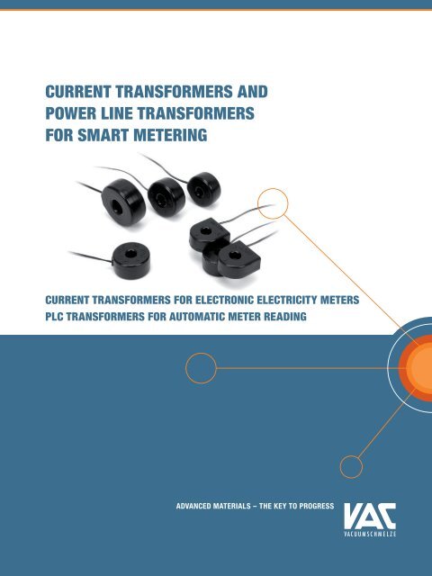
<strong>Current</strong> Transformers <strong>and</strong><br />
<strong>Power</strong> <strong>Line</strong> Transformers<br />
for Smart Metering<br />
<strong>Current</strong> Transformers for Electronic Electricity Meters<br />
PLC Transformers for Automatic Meter Reading<br />
Advanced Materials – The Key to Progress
THE COMPANY<br />
VACUUMSCHMELZE<br />
The company has a staff of approximately 4.500, is represented in 40 countries spread<br />
across all continents <strong>and</strong> currently registers a turnover of more than EUR 350 million. The<br />
headquaters <strong>and</strong> operational center of VAC is in Hanau, Germany. The company also has<br />
production plants in Slovakia, Finl<strong>and</strong>, Malaysia <strong>and</strong> China.<br />
CONTENTS<br />
1. Introduction page 3<br />
2. <strong>Current</strong> Transformers for Smart Metering page 4<br />
3. PLC Transformers for Smart Metering page 15<br />
4. Typical Dependence of Phase <strong>and</strong> Amplitude Errors page 17<br />
5. Typical <strong>Line</strong>arity Behavior of Different VAC Core Materials page 30<br />
6. Typical Characteristic of Amplitude Error vs. Primary <strong>Current</strong> page 30<br />
7. Typical Characteristic of Amplitude Error vs. Unipolar Primary <strong>Current</strong> page 31<br />
8. Appendices:<br />
A - Ensuring the Measuring Accuracy of Electricity Meters page 32<br />
B – Difference from Combined Core CTs page 35<br />
2 <strong>Current</strong> Transformers <strong>and</strong> <strong>Power</strong> <strong>Line</strong> Transformers for Smart Metering
<strong>Current</strong> Transformers <strong>and</strong><br />
<strong>Power</strong> <strong>Line</strong> Transformers<br />
for Smart Metering<br />
VACUUMSCHMELZE GmbH & Co. KG (VAC) is<br />
one of the worldwide leading manufacturers<br />
of metallic materials <strong>and</strong> inductive components<br />
manufactured from these alloys. VAC<br />
has been supplying high-performance products<br />
for more than 30 years.<br />
Smart Metering<br />
For more than ten years we have focused on high-precision<br />
current <strong>transformers</strong> for use in electronic electricity meters.<br />
Developing <strong>and</strong> improving our own materials like VITROVAC ®<br />
<strong>and</strong> VITROPERM ® , produced by rapid solidification technology,<br />
we are in a leading position to serve the metering industry<br />
with high-performance current <strong>transformers</strong>.<br />
Our R&D <strong>and</strong> Engineering departments can provide outst<strong>and</strong>ing<br />
competence in designing cores <strong>and</strong> components<br />
for the metering industry worldwide. In total more than 30<br />
million meters operate with VAC materials.<br />
Technical st<strong>and</strong>ards define requirements for accuracy for<br />
measuring of power in different operation modes. In Europe<br />
<strong>and</strong> other non-European countries these are usually the<br />
st<strong>and</strong>ards IEC 62053 -21, -22, -23 <strong>and</strong>, for the American<br />
market, the st<strong>and</strong>ards of the ANSI C12.xx series.<br />
®<br />
registered trademark of VACCUUMSCHMELZE GmbH & Co. KG<br />
<strong>Current</strong> Transformers <strong>and</strong> <strong>Power</strong> <strong>Line</strong> Transformers for Smart Metering<br />
3
<strong>Current</strong> Transformers<br />
for Smart Metering<br />
Measurement Principles<br />
The key component in smart meters is the current transducer.<br />
There is a number of functional principles for implementation<br />
of the current transducer.<br />
The shunt resistor is a favourite choice because of its very<br />
low cost <strong>and</strong> good linearity, but designers have to be aware<br />
of its disadvantages. Because of the regulations concerning<br />
maximum power consumption (2 W per phase acc. to IEC<br />
62053 -21, -23), its resistance is limited to some hundreds of<br />
µ. This low value results in very low secondary voltages at<br />
low primary currents.<br />
These have to be very carefully filtered <strong>and</strong> amplified to keep<br />
the meter’s specified accuracy in the low current level. Heat<br />
dissipation within the meter is another critical point to be<br />
considered. In cases of multi-phase meters or single-phase<br />
meters with external interface, additional galvanic separation<br />
has to be provided to prevent hazardous operation or<br />
short-circuit conditions between the phases. In most cases<br />
optocouplers <strong>and</strong> separation <strong>transformers</strong> will additionally be<br />
needed, increasing the meter’s overall cost.<br />
Another favourite principle is the Rogowski coil, which does<br />
not exhibit saturation effects due to its coreless operation.<br />
The disadvantage of this is common to all open magnetic<br />
circuits <strong>and</strong> results in very interference-sensitive operation.<br />
Costly shielding has to be provided to keep measurement<br />
errors small at low primary currents. Designs using Hall sensor<br />
devices have to be clearly separated: the low-cost types<br />
can suffer from ageing effects which can deteriorate accuracy<br />
over time; stabilised designs will control these effects, but at<br />
the cost of complicated compensation circuitry.<br />
4 <strong>Current</strong> Transformers <strong>and</strong> <strong>Power</strong> <strong>Line</strong> Transformers for Smart Metering
Overview of Established Measurement Principles in Electricity Meters<br />
• <strong>Current</strong> Transformers<br />
Safe Galvanic Separation<br />
High Dynamic Range<br />
• Shunt<br />
Low Dynamic Range<br />
No Galvanic Separation<br />
• Rogowski<br />
Coreless Coil<br />
Very Small Signals<br />
Requires Integrator<br />
• Hall Sensor<br />
Semiconductor Material<br />
Material Ageing<br />
Complex Signal Processing<br />
In comparison to other principles, toroidal-core current <strong>transformers</strong> with low burden resistors have several obvious advantages:<br />
• closed magnetic circuit:<br />
less sensitive to interference fields<br />
usually no shielding required<br />
• magnetic function principle without semiconductors: high long-term stability<br />
no need for additional circuitry<br />
• simple assembly involving few parts:<br />
low assembly expenses, compact designs<br />
attractive prices<br />
easy to mount<br />
<strong>Current</strong> Transformers <strong>and</strong> <strong>Power</strong> <strong>Line</strong> Transformers for Smart Metering<br />
5
Characteristics <strong>Current</strong> Transformer Shunt Rogowski Coil Hall Sensor<br />
Dynamic Range / <strong>Line</strong>arity + + + +<br />
Temperature Stability + 0 ++ +<br />
Corrosion / Reliability ++ -- ++ ++<br />
Energy Dissipation ++ -- ++ ++<br />
Galvanic Insulation ++ -- ++ ++<br />
Output Signal Level ++ - 0 0<br />
Mounting ++ + -- --<br />
Sensitivity against external AC + DC Fields 0 - -- --<br />
++ : excellent + : good 0 : average - : weak -- : disadvantageous<br />
The properties of the toroidal core current <strong>transformers</strong>, such<br />
as maximum transmissible primary current, amplitude <strong>and</strong><br />
phase error as well as linearity, are basically determined by<br />
the material used for the magnetic core. The three areas of<br />
application mentioned place different dem<strong>and</strong>s on the respective<br />
materials:<br />
For meters according to IEC 62053-22 <strong>and</strong> ANSI C12.xx, the<br />
best materials are those with high permeability in connection<br />
with the comparatively high flux density ranges of the metallic<br />
materials <strong>and</strong> only slight changes in properties as a function<br />
of the temperature. <strong>Current</strong> <strong>transformers</strong> with high-grade<br />
amorphous VITROVAC or nanocrystalline VITROPERM alloys<br />
from VAC offer extra advantages to the users:<br />
• very small <strong>and</strong> high linear phase <strong>and</strong> amplitude error<br />
• easily compensable phase error<br />
• extreme low temperature dependence<br />
Meters according to IEC 62053 -21, -23 must have tolerance<br />
to DC current components (‚direct current tolerance‘) which<br />
can saturate conventional current <strong>transformers</strong> when unipolar<br />
alternating currents occur, e.g. from power supply units<br />
with primary side diodes.<br />
Magnetic cores made of very linear but still highly excitable<br />
amorphous <strong>and</strong> nanocrystalline low permeability alloys from<br />
VAC are used for this. These provide the current transformer<br />
with excellent properties:<br />
• st<strong>and</strong>ard compliant DC tolerance without air gap<br />
• negligible small amplitude error<br />
• extreme linear, easily compensable phase curve<br />
• low temperature dependence<br />
6 <strong>Current</strong> Transformers <strong>and</strong> <strong>Power</strong> <strong>Line</strong> Transformers for Smart Metering
Principle of Circuitry<br />
Phase <strong>and</strong> amplitude errors are critical for electricity measurement<br />
accuracy when current <strong>transformers</strong> are used. With<br />
meters of medium accuracy without DC tolerance, both have<br />
very low absolute values <strong>and</strong> can therefore be easily compensated<br />
by a simple correction in the circuit.<br />
<strong>Current</strong> <strong>transformers</strong> with DC tolerance have the special feature<br />
of a relatively high absolute phase error value at high<br />
constancy, whereas the amplitude error is negligibly small.<br />
This causes an energy measurement error which varies only<br />
slightly with the primary current <strong>and</strong> which adopts impermissibly<br />
high values on complex loads (e.g. inductive load with<br />
cos = 0.5) if the phase error is not carefully compensated.<br />
Since the specified scatter of the secondary inductance L<br />
cannot be reduced at will, the phase error of the individual<br />
current transformer is scattered to the same extent. An individual<br />
correction is therefore recommended to stay reliably<br />
within the error limits. This can be performed with a suitable<br />
digital signal processor (DSP) which is digitally adjusted to<br />
the implemented current transformer in a calibration run at<br />
a single current value (e.g. at I b<br />
). Particularly high accuracy<br />
can be achieved when the phase error curve is measured<br />
at several currents <strong>and</strong> is approximated between these for<br />
correction.<br />
This is often impossible, or only possible to a certain extent,<br />
in devices with DSPs of a simple internal structure. Here correction<br />
is possible by means of an RC low-pass connected in<br />
series with the analogue current measuring input (see page 9).<br />
Because of the scatter of the L-values, adapted use of grouped<br />
C-values may be necessary.<br />
If further modifications of the operating parameters are necessary,<br />
we offer recalculation of the error characteristics<br />
upon request.<br />
Summarized Overview of 60 A <strong>and</strong> 100 A <strong>Current</strong> Transformers<br />
60 A <strong>and</strong> 100 A are the most important current ranges worldwide. The following table shows available variations for both current ranges:<br />
I max<br />
Order Code<br />
T60404-<br />
Design<br />
Wire<br />
Pin<br />
VITROPERM<br />
Alloy<br />
VITROPERM<br />
Compact<br />
VITROVAC<br />
Shielding<br />
DC Tolerance<br />
60 A<br />
100 A<br />
...E4624-X...<br />
...E4626-X...<br />
101 X X X<br />
501 X X<br />
121 X X X<br />
521 X X X<br />
131 X X X<br />
531 X X X<br />
151 X X X X<br />
171 X X X X<br />
002 X X<br />
502 X X<br />
<strong>Current</strong> Transformers <strong>and</strong> <strong>Power</strong> <strong>Line</strong> Transformers for Smart Metering<br />
7
Block Diagram of an Electronic Electricity Meter<br />
Optical<br />
Interface<br />
DISPLAY<br />
PLC-<br />
Transceiver<br />
Keyboard<br />
IC<br />
A/D<br />
C<br />
<strong>Current</strong><br />
Transformer<br />
Load<br />
I L (t)<br />
L<br />
N<br />
U L (t)<br />
Mains<br />
8 <strong>Current</strong> Transformers <strong>and</strong> <strong>Power</strong> <strong>Line</strong> Transformers for Smart Metering
Table 1: <strong>Current</strong> Transformers with DC Tolerance according to IEC – Based on Vitrovac<br />
Order Code<br />
T60404-...<br />
Primary<br />
<strong>Current</strong> Range<br />
Ratio Phase<br />
Error<br />
Characteristic Values Dimensions<br />
Error<br />
Curves<br />
[fig./<br />
page]<br />
I max<br />
[A rms<br />
]<br />
Î peak<br />
[A 0p<br />
]<br />
1 : [ ] (I)<br />
[°]<br />
L<br />
[H]<br />
R DC<br />
[]<br />
R B<br />
[]<br />
U B<br />
[V rms<br />
]<br />
Inner dia.<br />
Ø<br />
[mm]<br />
Width<br />
D<br />
[mm]<br />
Heigth<br />
H<br />
[mm]<br />
...E4622-X101 1/17 20 20 2500 3.62 4.6 54 37.5 0.3 5 28.5 14.5 Wire<br />
...E4623-X101 2/17 40 40 2500 4.15 3.7 66 18.8 0.3 5.5 28 16 Wire<br />
...E4624-X101 3/18 60 60 2500 4.06 3.0 55 12.5 0.3 8 30.5 15 Wire<br />
...E4624-X501 3/18 60 60 2500 4.06 3.0 55 12.5 0.3 8.5 31 14 Pin<br />
...E4625-X101 4/18 80 80 2500 5.15 2.4 59 9.4 0.3 8 30.5 15 Wire<br />
...E4625-X501 4/18 80 80 2500 5.15 2.4 59 9.4 0.3 8.5 31 14 Pin<br />
...E4626-X101 5/19 100 100 2500 4.48 2.1 44 7.5 0.3 9.5 35 15 Wire<br />
...E4626-X501 5/19 100 100 2500 4.48 2.1 44 7.5 0.3 11.5 34 14 Pin<br />
...E4627-X101 6/19 120 120 2500 4.07 1.8 34 6.25 0.3 12 39 18 Wire<br />
Pin/<br />
Wire<br />
Table 2: <strong>Current</strong> Transformers with DC Tolerance according to IEC – – Based on Vitroperm<br />
Order Code<br />
T60404-...<br />
Primary<br />
<strong>Current</strong> Range<br />
Ratio Phase<br />
Error<br />
Characteristic Values Dimensions<br />
Error<br />
Curves<br />
[fig./<br />
page]<br />
I max<br />
[A rms<br />
]<br />
Î peak<br />
[A 0p<br />
]<br />
1 : [ ] (I)<br />
[°]<br />
L<br />
[H]<br />
R DC<br />
[]<br />
R B<br />
[]<br />
U B<br />
[V rms<br />
]<br />
Inner dia.<br />
Ø<br />
[mm]<br />
Width<br />
D<br />
[mm]<br />
Heigth<br />
H<br />
[mm]<br />
...E4622-X121 7/20 20 20 2500 2.0 9.23 70.6 37.5 0.3 5 30.9 16.0 Wire<br />
...E4623-X121 8/20 40 40 2500 2.1 6.5 60 18.75 0.3 7 33.8 16.9 Wire<br />
...E4624-X121 9/21 60 60 2500 2.3 5.05 51.5 12.5 0.3 8 37.5 18.1 Wire<br />
...E4624-X131 10/21 60 60 2500 3.5 3.8 71.5 12.5 0.3 8 32.7 16.3 Wire<br />
...E4624-X531 10/21 60 60 2500 3.5 3.8 71.5 12.5 0.3 8 32.7 16.3 Pin<br />
...E4625-X121 11/22 80 80 2500 2.4 3.5 42 9.38 0.3 10 40.8 18.5 Wire<br />
...E4625-X131 12/22 80 80 2500 3.4 3.33 62 9.38 0.3 9 36.8 17.4 Wire<br />
...E4626-X121 13/23 100 100 2500 2.4 2.77 35.5 7.5 0.3 10.5 43.2 19.8 Wire<br />
...E4626-X131 14/23 100 100 2500 3.3 3.1 49 7.5 0.3 9 38.1 17.7 Pin<br />
...E4626-X531 14/23 100 100 2500 3.3 3.1 49 7.5 0.3 9 38.1 17.7 Pin<br />
...E4627-X121 15/24 120 120 2500 4.1 3.1 37 6.25 0.3 12.5 45.5 19 Wire<br />
Pin/<br />
Wire<br />
<strong>Current</strong> Transformers <strong>and</strong> <strong>Power</strong> <strong>Line</strong> Transformers for Smart Metering<br />
9
Application Note:<br />
RC Components for Compensation of Phase Error<br />
The excellent soft magnetic properties of the VAC core<br />
material for DC-tolerant CTs leads to a negligible small<br />
amplitude error as well as to extremely low <strong>and</strong> linear<br />
temperature dependence. Due to the low permeability, a phase<br />
error of typically 4 ° to 5 ° occurs which is easy to compensate<br />
on account of its high constancy of typically +/- 0.05 °.<br />
Compensation can be effected digitally by appropriate<br />
correction in the microprocessor <strong>and</strong> analogously by a RC<br />
low-pass in front of the input of the A/D converter. A number<br />
of major metering chip providers supply tailored solutions for<br />
optimum performance <strong>and</strong> accuracy in combination with<br />
these CT types.<br />
C (R CU<br />
+ R B<br />
) / 2 R L<br />
Condition for value of R:<br />
RB
Table 3: Shielded <strong>Current</strong> Transformers for Anti-Tampering<br />
Order Code<br />
T60404-...<br />
Primary<br />
<strong>Current</strong> Range<br />
Ratio Phase<br />
Error<br />
Characteristic Values<br />
Error<br />
Curves<br />
[fig./<br />
page]<br />
I max<br />
[A rms<br />
]<br />
Î peak<br />
[A 0p<br />
]<br />
1 : [ ] (I)<br />
[°]<br />
L<br />
[H]<br />
R DC<br />
[]<br />
R B<br />
[]<br />
U B<br />
[V rms<br />
]<br />
Dimensions<br />
Inner dia.<br />
Ø<br />
[mm]<br />
Width<br />
D<br />
[mm]<br />
Heigth<br />
H<br />
[mm]<br />
...E4622-X011 20/26 6 - 2000 0.37 105 115 100 0.3 5.5 28 15.9 Wire<br />
...E4622-X012 21/27 6 - 2000 0.17 238 115 100 0.3 5.5 28 15.9 Wire<br />
...E4623-X171 8/20 40 40 2500 2.1 6.5 60 18.75 0.3 6 38.5 20 Wire<br />
...E4624-X151 3/18 60 60 2500 4.06 3.0 55 12.5 0.3 8 32.9 17.1 Wire<br />
...E4624-X171 9/21 60 60 2500 3.5 3.8 71.5 12.5 0.3 8 36.9 19.2 Wire<br />
...E4625-X151 4/18 80 80 2500 5.15 2.4 53.5 9.4 0.3 8 32.9 17.1 Wire<br />
...E4626-X151 5/19 100 100 2500 4.48 1.97 55 7.5 0.3 9.5 35.8 17.2 Wire<br />
Pin/<br />
Wire<br />
Typical characteristic of the amplitude error in the field of a permanent magnet<br />
Sensitivity of E4624-X101/151 for DC magnetic fields<br />
Magnet: VACOMAX ® 65 x 65 x 35 mm<br />
0<br />
Amplitude error F(Iprim ) [%]<br />
-50<br />
...-X151 + 3 mm<br />
shielding plate<br />
...-X151<br />
(shielded)<br />
...-X101<br />
(unshielded)<br />
-100<br />
0 10 20 30 40 50 60 70<br />
Distance between magnet <strong>and</strong> CT [mm]<br />
Diagram above shows a comparison of different shielding configurations. For optimum protection against external magnetic fields CTs<br />
from …–X151 series <strong>and</strong> a 3 mm shielding plate are needed.<br />
®<br />
registered trademark of Vacuumschmelze GmbH & Co. KG<br />
<strong>Current</strong> Transformers <strong>and</strong> <strong>Power</strong> <strong>Line</strong> Transformers for Smart Metering<br />
11
Table 4: <strong>Current</strong> Transformers without DC tolerance for direct connection<br />
Order Code<br />
T60404-...<br />
Primary<br />
<strong>Current</strong> Range<br />
Ratio Phase<br />
Error<br />
Characteristic Values Dimensions<br />
Error<br />
Curves<br />
[fig./<br />
page]<br />
I max<br />
[A rms<br />
]<br />
Î peak<br />
[A 0p<br />
]<br />
1 : [ ] (I)<br />
[°]<br />
L<br />
[H]<br />
R DC<br />
[]<br />
R B<br />
[]<br />
U B<br />
[V rms<br />
]<br />
Inner dia.<br />
Ø<br />
[mm]<br />
Width<br />
D<br />
[mm]<br />
Heigth<br />
H<br />
[mm]<br />
...E4622-X002 16/24 20 - 2500 0.18 113 54 37.5 0.3 5 28.5 14.5 Wire<br />
...E4623-X002 17/25 40 - 2500 0.12 155 61 18.8 0.3 5.5 28 16 Wire<br />
...E4624-X002 18/25 60 - 2500 0.13 122 55 12.5 0.3 8 30.5 15 Wire<br />
...E4624-X502 18/25 60 - 2500 0.13 122 55 12.5 0.3 8.5 31 14 Pin<br />
...E4626-X002 19/26 100 - 2500 0.11 97 44 7.5 0.3 9.5 35 15 Wire<br />
...E4626-X502 19/26 100 - 2500 0.11 97 44 7.5 0.3 11.5 34 14 Pin<br />
Pin/<br />
Wire<br />
Table 5: <strong>Current</strong> Transformers without DC tolerance for indirect connection<br />
Order Code<br />
T60404-...<br />
Primary<br />
<strong>Current</strong> Range<br />
Ratio Phase<br />
Error<br />
Characteristic Values Dimensions<br />
Error<br />
Curves<br />
[fig./<br />
page]<br />
I max<br />
[A rms<br />
]<br />
Î peak<br />
[A 0p<br />
]<br />
1 : [ ] (I)<br />
[°]<br />
L<br />
[H]<br />
R DC<br />
[]<br />
R B<br />
[]<br />
U B<br />
[V rms<br />
]<br />
Inner dia.<br />
Ø<br />
[mm]<br />
Width<br />
D<br />
[mm]<br />
Heigth<br />
H<br />
[mm]<br />
...E4629-X007 20/26 6 - 2000 0.37 105 112 100 0.3 7.0 23.0 11.0 Wire<br />
...E4622-X501 20/26 6 - 2000 0.37 110 115 100 0.3 6.3 24.5 11.5 Pin<br />
...E4629-X010 21/27 6 - 2000 0.17 238 114 30 0.3 7.0 23 11 Wire<br />
...E4622-X503 21/27 6 - 2000 0.17 238 114 100 0.3 6.3 24.5 11.5 Pin<br />
...E4658-X043 22/27 6 - 1500 0.4 35 46 75 0.3 5.0 16.8 9 Pin<br />
Pin/<br />
Wire<br />
12 <strong>Current</strong> Transformers <strong>and</strong> <strong>Power</strong> <strong>Line</strong> Transformers for Smart Metering
Table 6: <strong>Current</strong> Transformers for ANSI market<br />
Order Code<br />
T60404-...<br />
Primary<br />
<strong>Current</strong> Range<br />
Ratio Phase<br />
Error<br />
Characteristic Values<br />
Error<br />
Curves<br />
[fig./<br />
page]<br />
I max<br />
[A rms<br />
]<br />
Î peak<br />
[A 0p<br />
]<br />
1 : [ ] (I)<br />
[°]<br />
L<br />
[H]<br />
R DC<br />
[]<br />
R B<br />
[]<br />
U B<br />
[V rms<br />
]<br />
Dimensions<br />
Inner dia.<br />
Ø<br />
[mm]<br />
Width<br />
D<br />
[mm]<br />
Heigth<br />
H<br />
[mm]<br />
...E4629-X007 23/28 20 - 2000 0.21 105 112 30 0.3 7.0 23.0 11.0 Wire<br />
...E4622-X501 23/28 20 - 2000 0.21 110 115 30 0.3 6.3 24.5 11.5 Pin<br />
...E4629-X010 24/28 20 - 2000 0.17 238 114 30 0.3 7.0 23.0 11.0 Wire<br />
...E4622-X503 24/28 20 - 2000 0.17 238 114 30 0.3 6.3 24.5 11.5 Pin<br />
...E4627-X001 25/29 200 - 1000 0.11 24.6 13.5 1.5 0.3 8.5 30.0 17.5 Wire<br />
...E4628-X001 26/29 320 - 1000 0.10 22 12.7 0.94 0.3 11.0 35.0 18.5 Wire<br />
Pin/<br />
Wire<br />
Explanations of tables 1 to 6:<br />
Noted values are typical at room temperature (25 °C)<br />
All types are designed as bar-type CTs with one primary turn<br />
(N 1<br />
= 1).<br />
I max<br />
= maximum AC primary current with defined errors<br />
Î peak<br />
= max. half wave rectified AC amplitude without saturation<br />
(for Class 1 meter (IEC 62053 -21, -23):<br />
F(Î max<br />
) < 3 %)<br />
(I) = max. phase error for I < I max<br />
R B<br />
U B<br />
Ø<br />
D<br />
H<br />
= burden resistor<br />
= output voltage across burden resistor R B<br />
at I max<br />
= diameter of centre hole<br />
= maximum width of component in mm<br />
= maximum thickness of component in mm<br />
For further details please see datasheets, which are provided<br />
on www.vacuumschmelze.com.<br />
F(I) = max. amplitude error for I < I max<br />
N 2<br />
= number of secondary turns<br />
L = inductance at moderate excitation level (I < Imax)<br />
R DC<br />
= winding resistance<br />
<strong>Current</strong> Transformers <strong>and</strong> <strong>Power</strong> <strong>Line</strong> Transformers for Smart Metering<br />
13
Examples for customised current<br />
transformer designs<br />
In addition to the illustrated st<strong>and</strong>ard types, customised developments<br />
(see above) are also possible when sufficiently large<br />
quantities are needed. Please ask for our latest CT checklist,<br />
fill out as completely as possible <strong>and</strong> send it back to us.<br />
If the sensitivity of the current transformer to external magnetic<br />
fields in special applications is still too high, we recommend<br />
shielded versions of CTs (see table 3 on page 10). If<br />
required, for anti-tampering issues each CT can be encapsulated<br />
with a pair of deep drawing caps.<br />
Dielectric Strength Test:<br />
For st<strong>and</strong>ard type housings the following values are valid for<br />
the insulation between a bare copper primary conductor <strong>and</strong><br />
the secondary winding (different test values on request):<br />
U p rms<br />
= 2,5 kV (50 / 60 Hz, 1 min) <strong>and</strong><br />
U p max<br />
= 6 kV (1,2 µs / 50 µs – test pulse)<br />
For additional protection against manipulation by external<br />
fields from permanent magnets, a metal plate may be placed<br />
between CT <strong>and</strong> the magnet (see diagram on page 10).<br />
14 <strong>Current</strong> Transformers <strong>and</strong> <strong>Power</strong> <strong>Line</strong> Transformers for Smart Metering
PLC Transformers for Smart Metering<br />
In the years to come, ‘Smart Grids’ will take on greater significance<br />
<strong>and</strong> electronic electricity meters newly installed for<br />
this purpose will increasingly be networked to enable processes<br />
including remote meter reading.<br />
Electronic electricity meters must therefore be able to communicate,<br />
<strong>and</strong> secure data transfer must be guaranteed. Various<br />
communication technologies are available for Automatic<br />
Meter Reading (AMR). In the case of wired transfer technologies,<br />
power line communication (PLC) is one of the favoured<br />
technologies.<br />
VAC component characteristics are aligned <strong>and</strong> optimized<br />
for low EMC interference, low distortion <strong>and</strong> high dielectric<br />
strength. These key parameters for PLC <strong>transformers</strong> offer<br />
particularly significant advantages for users with respect to<br />
secure data transmission.<br />
Block diagram of an electronic meter with PLC read-out system<br />
Optical<br />
Interface<br />
DISPLAY<br />
PLC-<br />
Transceiver<br />
Keyboard<br />
IC<br />
A/D<br />
C<br />
<strong>Current</strong><br />
Transformer<br />
Load<br />
I L (t)<br />
L<br />
N<br />
U L (t)<br />
Mains<br />
<strong>Current</strong> Transformers <strong>and</strong> <strong>Power</strong> <strong>Line</strong> Transformers for Smart Metering<br />
15
Table 7: PLC Transformers for Metering Applications<br />
Order Code<br />
T60403-K…<br />
Turns<br />
Ratio<br />
L [mH] R cu<br />
[m] L s<br />
[µH]<br />
Capacitor<br />
C K<br />
[pF]<br />
HV Test*<br />
[kV rms<br />
]<br />
Design**<br />
5024-X044 1:1 1.4 200 : 200 0.3 25 6 SMD<br />
4081-X004<br />
200 : 300<br />
PTH flat<br />
1:1 1.4<br />
0.3 25 4<br />
4085-X004 200 : 300 PTH upright<br />
5024-X078 1:1 2.5 200 : 300 0.9 50 3 SMD<br />
4096-X046 1:1 1.3 100 : 150 1 12 6 PTH<br />
4096-X047 1:1 1.3 100 : 200 10 5 6 PTH<br />
4096-X048 1:1 1.3 100 : 200 10 5 6 PTH<br />
4021-X139 1.67:1 0.5 300 : 200 5 5 6 PTH<br />
5024-X097 1.68:1 1.2 220 : 160 5.8 17 1.5*** SMD<br />
4031-X009 2:1 1.0 140 : 80 0.67 17 4 PTH<br />
5024-X079 2:1 1.4 350 : 120 2 50 3 SMD<br />
5024-X090 1:1:2 0.88 100 : 100 : 100 0.4 30 3 SMD<br />
5024-X092**** 1:1:2 0.7 250: 250 : 500 0.99 37.5 4 SMD<br />
5024-X099**** 1:1:2 0.7 250 : 250 : 500 0.99 37.5 3 SMD<br />
5032-X102 1:1:2 0.7 135 : 135 : 230 0.73 25.27 7.5 SMD<br />
* = reinforced insulation according to EN60950<br />
** = mechanical outline; for details see VAC datasheet (available upon request)<br />
*** = operational insulation<br />
**** = extended performance in the low frequency range<br />
Table 8: PLC Transformers Cross Reference List<br />
Order Code<br />
T60403-K…<br />
Echelon Maxim On Semi Renesas<br />
M16C/6S<br />
STM TI<br />
C2000<br />
Yitran<br />
IT800<br />
PLT-21<br />
PLT-22<br />
PLT3120<br />
PLT3150<br />
MAX2990<br />
MAX2991<br />
AMIS<br />
49587<br />
ST7536<br />
ST7537<br />
ST7538<br />
ST7540<br />
5024-X044 X X X X X X<br />
4081-X004<br />
4085-X004<br />
X X X X X X<br />
5024-X078 X X X X<br />
4096-X046 X X X X X<br />
4096-X047 X X X X<br />
4096-X048 X<br />
4021-X139 X X X<br />
5024-X097 X X<br />
4031-X009 X X<br />
5024-X079 X<br />
5024-X090 X X X X<br />
5024-X092* X X X X X<br />
5024-X099* X X X X X<br />
5032-X102 X X<br />
* = extended performance in the low-frequency range<br />
16 <strong>Current</strong> Transformers <strong>and</strong> <strong>Power</strong> <strong>Line</strong> Transformers for Smart Metering
Typical Temperature Dependence of Phase<br />
<strong>and</strong> Amplitude Errors<br />
Fig. 1: 20 A with DC Tolerance, T60404-E4622-X101<br />
Fig. 2: 40 A with DC Tolerance, T60404-E4623-X101<br />
<strong>Current</strong> Transformers <strong>and</strong> <strong>Power</strong> <strong>Line</strong> Transformers for Smart Metering<br />
17
Fig. 3: 60 A with DC Tolerance, T60404-E4624-X101/-X501/-X151<br />
Fig. 4: 80 A with DC Tolerance, T60404-E4625-X101/-X501/-X151<br />
18 <strong>Current</strong> Transformers <strong>and</strong> <strong>Power</strong> <strong>Line</strong> Transformers for Smart Metering
Fig. 5: 100 A with DC Tolerance, T60404-E4626-X101/-X501/-X151<br />
Fig. 6: 120 A with DC Tolerance, T60404-E4627-X101<br />
<strong>Current</strong> Transformers <strong>and</strong> <strong>Power</strong> <strong>Line</strong> Transformers for Smart Metering<br />
19
Fig. 7: 20 A with DC Tolerance, T60404-E4622-X121<br />
3,0<br />
0,3<br />
2,5<br />
0,2<br />
2,0<br />
0,1<br />
1,5<br />
0<br />
1,0<br />
-0,1<br />
0,5<br />
-0,2<br />
0,1 1 10 100 1000<br />
Fig. 8: 40 A with DC Tolerance, T60404-E4623-X121/-X171<br />
3,0<br />
0,4<br />
2,5<br />
0,3<br />
2,0<br />
0,2<br />
1,5<br />
0,1<br />
1,0<br />
0<br />
0,5<br />
-0,1<br />
0,0 -0,2<br />
0,1 1 10 100 1000<br />
20 <strong>Current</strong> Transformers <strong>and</strong> <strong>Power</strong> <strong>Line</strong> Transformers for Smart Metering
Fig. 9: 60 A with DC Tolerance, T60404-E4624-X121/-X171<br />
3,5<br />
1<br />
3,0<br />
0,75<br />
2,5<br />
0,5<br />
2,0<br />
0,25<br />
1,5<br />
0<br />
1,0<br />
-0,25<br />
0,5 -0,5<br />
0,1 1 10 100 1000<br />
Fig. 10: 60 A with DC Tolerance, T60404-E4624-X131/-X531<br />
5,0<br />
4,5<br />
4,0<br />
3,5<br />
3,0<br />
2,5<br />
2,0<br />
1,5<br />
1,25<br />
1,00<br />
0,75<br />
0,50<br />
0,25<br />
0<br />
-0,25<br />
-0,50<br />
1,0 -0,75<br />
0,1 1 10 100 1000<br />
<strong>Current</strong> Transformers <strong>and</strong> <strong>Power</strong> <strong>Line</strong> Transformers for Smart Metering<br />
21
Fig. 11: 80 A with DC Tolerance, T60404-E4625-X121<br />
4,0<br />
3,5<br />
3,0<br />
2,5<br />
2,0<br />
1,5<br />
1,0<br />
0,5<br />
1,50<br />
1,25<br />
1,00<br />
0,75<br />
0,50<br />
0,25<br />
0<br />
-0,25<br />
0,0 -0,50<br />
0,1 1 10 100 1000<br />
Fig. 12: 80 A with DC Tolerance, T60404-E4625-X131/-X531<br />
6,0<br />
5,5<br />
5,0<br />
4,5<br />
4,0<br />
3,5<br />
3,0<br />
2,5<br />
2,0<br />
1,5<br />
1,75<br />
1,50<br />
1,25<br />
1,00<br />
0,75<br />
0,50<br />
0,25<br />
0<br />
-0,25<br />
-0,50<br />
1,0<br />
-0,75<br />
0,1 1 10 100 1000<br />
22 <strong>Current</strong> Transformers <strong>and</strong> <strong>Power</strong> <strong>Line</strong> Transformers for Smart Metering
Fig. 13: 100 A with DC Tolerance, T60404-E4626-X121<br />
4,5<br />
4,0<br />
3,5<br />
3,0<br />
2,5<br />
2,0<br />
1,5<br />
1,0<br />
0,5<br />
0,5<br />
0,4<br />
0,3<br />
0,2<br />
0,1<br />
0<br />
-0,1<br />
-0,2<br />
-0,3<br />
0,0<br />
-0,4<br />
0,1 1 10 100 1000<br />
Fig. 14: 100 A with DC Tolerance, T60404-E4626-X131/-X531<br />
5,0<br />
4,5<br />
4,0<br />
3,5<br />
3,0<br />
2,5<br />
2,0<br />
1,5<br />
1,25<br />
1,00<br />
0,75<br />
0,50<br />
0,25<br />
0<br />
-0,25<br />
-0,50<br />
1,0 -0,75<br />
0,1 1 10 100 1000<br />
<strong>Current</strong> Transformers <strong>and</strong> <strong>Power</strong> <strong>Line</strong> Transformers for Smart Metering<br />
23
Fig. 15: 120 A with DC Tolerance, T60404-E4627-X121<br />
5,0<br />
4,5<br />
4,0<br />
3,5<br />
3,0<br />
2,5<br />
2,0<br />
1,5<br />
1,0<br />
1,75<br />
1,50<br />
1,25<br />
1,00<br />
0,75<br />
0,50<br />
0,25<br />
0,00<br />
-0,25<br />
0,5<br />
-0,50<br />
0,0<br />
-0,75<br />
0,1 1 10 100 1000<br />
Fig. 16: 20 A, T60404-E4622-X002<br />
0,2<br />
0,18<br />
0,16<br />
0,14<br />
0,12<br />
0,10<br />
0,08<br />
0,06<br />
0,40<br />
0,35<br />
0,30<br />
0,25<br />
0,20<br />
0,15<br />
0,10<br />
0,05<br />
0,00<br />
-0,05<br />
0,04 -0,10<br />
0,1 1 10 100 1000<br />
24 <strong>Current</strong> Transformers <strong>and</strong> <strong>Power</strong> <strong>Line</strong> Transformers for Smart Metering
Fig. 17: 40 A, T60404-E4623-X002<br />
Fig. 18: 60 A, T60404-E4624-X002/-X502<br />
<strong>Current</strong> Transformers <strong>and</strong> <strong>Power</strong> <strong>Line</strong> Transformers for Smart Metering<br />
25
Fig. 19: 100 A, T60404-E4626-X002/-X502<br />
Fig. 20: 6 A, T60404-E4629-X007, 4622-X501, 4622-X011<br />
26 <strong>Current</strong> Transformers <strong>and</strong> <strong>Power</strong> <strong>Line</strong> Transformers for Smart Metering
Fig. 21: 6 A, T60404-E4629-X010, 4622-X503, 4622-X012<br />
Fig. 22: 6 A, T60404-E4658-X043<br />
<strong>Current</strong> Transformers <strong>and</strong> <strong>Power</strong> <strong>Line</strong> Transformers for Smart Metering<br />
27
Fig. 23: 20 A, T60404-E4629-X007, 4622-X501<br />
Fig. 24: 20 A, T60404-E4629-X010, 4622-X503<br />
28 <strong>Current</strong> Transformers <strong>and</strong> <strong>Power</strong> <strong>Line</strong> Transformers for Smart Metering
Fig. 25: 200 A, T60404-E4627-X001<br />
Fig. 26: 320 A, T60404-E4628-X001<br />
<strong>Current</strong> Transformers <strong>and</strong> <strong>Power</strong> <strong>Line</strong> Transformers for Smart Metering<br />
29
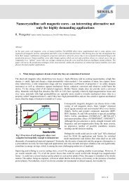
Typical linearity behaviour of different<br />
VAC core materials<br />
Classical crystalline 80 % NiFe vs. rapid solified VAC alloys<br />
Typical characteristic of amplitude<br />
error vs. primary current<br />
100 A, T60404-E4626-X101/-X501<br />
30 <strong>Current</strong> Transformers <strong>and</strong> <strong>Power</strong> <strong>Line</strong> Transformers for Smart Metering
Typical Characteristic of Amplitude<br />
Error vs. Unipolar (half-wave rectified)<br />
Primary <strong>Current</strong><br />
100 A, T60404-E4626-X101/-X501<br />
<strong>Current</strong> Transformers <strong>and</strong> <strong>Power</strong> <strong>Line</strong> Transformers for Smart Metering<br />
31
Appendix A<br />
Recommendation: Ensuring the Measuring Accuracy of Electricity Meters<br />
1. Measuring Sensitivity for Low Loads<br />
According to table 6 of IEC 62053-21 the percentage error limits for meters of class 1 (balanced loads) are specified as follows:<br />
Value of current<br />
for direct connected meters<br />
for meters of class 1<br />
Percentage error limits<br />
There are no limits specified in the low load range below 0.05 I b<br />
(e.g. for accurate metering of st<strong>and</strong>-by modus of electronic<br />
devices, low energy lamps…).<br />
0.05 I b<br />
3. Immunity against External Magnetic Fields<br />
According to table 8 of IEC 62053-21 the immunity of meters against external magnetic fields shall be as follows:<br />
Influence quantity<br />
Continuous magnetic<br />
induction of external origin<br />
Magnetic induction of<br />
external origin 0.5 mT<br />
for direct connected<br />
meters<br />
Value of current<br />
for transformer<br />
operated meters<br />
<strong>Power</strong><br />
Factor<br />
Limits of variation<br />
in percentage error<br />
for meters of class<br />
1 2<br />
I b<br />
I n<br />
1 2.0 3.0<br />
I b<br />
I n<br />
1 2.0 3.0<br />
The conditions specified are adequate for normal environmental conditions.<br />
In recent years requirements concerning much stronger fields have been discussed by metering regulators to also take into account<br />
potential tampering with meters. These requirements led to considerable efforts by meter manufacturers, e.g. encapsulation of the<br />
meter’s susceptible components against strong rare earth magnets using magnetic shielding.<br />
However, it must be realised that not only permanent magnets, but also coils creating AC magnetic fields can potentially be used for<br />
tampering <strong>and</strong> that ultimately any measurement principle including the ‘old’ Ferraris meter can be manipulated in one way or the other.<br />
Of course, counter-measures such as magnetic shielding are also available for each measurement method. In the long run, the competition<br />
between factors such as increasing magnet dimensions <strong>and</strong> increasing shielding efforts cannot be won by any one of the parties<br />
involved, but does increase meter costs significantly.<br />
We therefore recommend introducing electronic means to detect tampering attempts <strong>and</strong> taking corresponding measures inside<br />
the meter’s electronics <strong>and</strong> communication system, while retaining the specifications cited above for field immunity requirements.<br />
For example, external magnetic influences of extreme field strength, clearly indicating tampering attempts, could be detected by<br />
cost-effective electronic sensors <strong>and</strong> generate an alarm signal at the front panel. Additionally, the alarm status should be stored<br />
within the meter’s data memory <strong>and</strong>, if a data exchange module is installed, communicated via the data interface to the data collection<br />
<strong>and</strong> evaluation site of the energy supplier.<br />
<strong>Current</strong> Transformers <strong>and</strong> <strong>Power</strong> <strong>Line</strong> Transformers for Smart Metering<br />
33
Appendix B<br />
Difference from Combined Core CTs<br />
In recent years CTs based on cores with two parts known as combined cores have appeared on the market. One part of the core is<br />
highly permeable while the second one is a low-permeable core for DC tolerance according to IEC 62053 -21, -23.<br />
At conditions with power factor cos < 1 <strong>and</strong> appearance of half rectified sinusoidal currents in the electricity grid, errors in measuring<br />
power can increase up to 18 %.<br />
The pictures below show the differences between ‘Single’ <strong>and</strong> ‘Combined’ cores.<br />
Single-Core CT<br />
Homogenous core (VAC – type, high linearity):<br />
• best linearity in amplitude <strong>and</strong> phase<br />
Meter with high-linearity CT measures correctly!<br />
Measurement accuracy: current IEC- test <strong>and</strong> proposal<br />
20.00<br />
test A (linear single core)<br />
15.00<br />
error (%)<br />
10.00<br />
5.00<br />
0.00<br />
0 5 10 15 20 25<br />
-5.00<br />
-10.00<br />
-15.00<br />
cos <br />
0.5i<br />
0.8i<br />
0.9i<br />
1<br />
0.9k<br />
-20.00<br />
• IEC-test cos = 1<br />
half-wave current (A)<br />
fine<br />
• proposal cos ≠ 1<br />
Error data between +0.6 % <strong>and</strong> -0.3 %<br />
Result: <strong>Power</strong> measurement independently from load <strong>and</strong> DC components!<br />
34 <strong>Current</strong> Transformers <strong>and</strong> <strong>Power</strong> <strong>Line</strong> Transformers for Smart Metering
Combined Core CT<br />
Combined core (2 core parts):<br />
• one high-permeability core part for AC operation<br />
• one non-linear low permeability core part for operation under DC components<br />
Meter with combined core CT behaves very sensitive.<br />
Measurement accuracy: current IEC-test <strong>and</strong> proposal<br />
20.00<br />
test B (combined core)<br />
15.00<br />
error (%)<br />
10.00<br />
5.00<br />
0.00<br />
0 5 10 15 20<br />
25<br />
-5.00<br />
-10.00<br />
-15.00<br />
cos <br />
0.5i<br />
0.8i<br />
0.9i<br />
1<br />
0.9k<br />
-20.00<br />
half-wave current (A)<br />
• IEC-test cos = 1<br />
satisfactory<br />
• proposal cos ≠ 1<br />
Error data between +18 % <strong>and</strong> -7,5 %<br />
Result: <strong>Power</strong> measurement depends strongly on load phase <strong>and</strong> DC components!<br />
<strong>Current</strong> Transformers <strong>and</strong> <strong>Power</strong> <strong>Line</strong> Transformers for Smart Metering<br />
35
vacuumschmelze gmbh & co. kg<br />
p.o. box 2253<br />
grüner weg 37<br />
d 63412 hanau / germany<br />
phone +49 6181 38 0<br />
fax +49 6181 38 2645<br />
info@vacuumschmelze.com<br />
www.vacuumschmelze.com<br />
vac sales usa llc<br />
2935 dolphin drive<br />
suite 102<br />
elizabethtown, ky 42701<br />
phone +1270 769 1333<br />
fax +1270 765 3118<br />
info-usa@vacuumschmelze.com<br />
VACUUMSCHMELZE<br />
Sales office singapore<br />
1 Tampines Central 5, #06-10/11<br />
CPF Tampines Building<br />
singapore 529508<br />
phone +65 6391 2600<br />
fax +65 6391 2601<br />
vacsingapore@vacuumschmelze.com<br />
PB-CT Edition 2012<br />
Published by VACUUMSCHMELZE GmbH & Co. KG, Hanau<br />
© VACUUMSCHMELZE 2012. All rights reserved.<br />
As far as patents or other rights of third parties are concerned, liability is<br />
only assumed for products per se, not for applications, processes <strong>and</strong> circuits<br />
implemented within these products. The information describes the<br />
type of product <strong>and</strong> shall not be considered as assured characteristics.<br />
Terms of delivery <strong>and</strong> rights to change design reserved.<br />
Advanced Materials – The Key to Progress