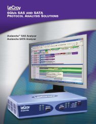
PCI Express 3.0 Characterization, Compliance ... - Teledyne LeCroy
PCI Express 3.0 Characterization, Compliance ... - Teledyne LeCroy
PCI Express 3.0 Characterization, Compliance ... - Teledyne LeCroy

You also want an ePaper? Increase the reach of your titles
YUMPU automatically turns print PDFs into web optimized ePapers that Google loves.
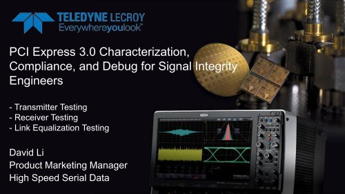
<strong>PCI</strong> <strong>Express</strong> <strong>3.0</strong> <strong>Characterization</strong>,<br />
<strong>Compliance</strong>, and Debug for Signal Integrity<br />
Engineers<br />
- Transmitter Testing<br />
- Receiver Testing<br />
- Link Equalization Testing<br />
David Li<br />
Product Marketing Manager<br />
High Speed Serial Data
Agenda<br />
• What is new about <strong>PCI</strong> <strong>Express</strong> (R) <strong>3.0</strong><br />
• Comparison to <strong>PCI</strong> <strong>Express</strong> (R) 2&1 Testing<br />
• What needs to be tested in <strong>PCI</strong> <strong>Express</strong> <strong>3.0</strong><br />
• <strong>Teledyne</strong> <strong>LeCroy</strong> and the <strong>PCI</strong>-SIG<br />
• SEG <strong>Compliance</strong> Testing<br />
• SEG Electrical Test Specifications<br />
• 5 Areas of Testing<br />
• Live Demo<br />
• Tx Link Equalization Section 2.4<br />
<strong>Teledyne</strong> <strong>LeCroy</strong> 2013<br />
2
<strong>PCI</strong> <strong>Express</strong> <strong>3.0</strong> Compared to <strong>PCI</strong>E 2&1<br />
<strong>PCI</strong> <strong>Express</strong> 2.0 <strong>PCI</strong> <strong>Express</strong> <strong>3.0</strong><br />
Bit Rate 5Gb/S 8Gb/s<br />
Encoding/Decoding 8B/10B 128B/130B<br />
Overhead 20% 1.5625%<br />
Scrambling Optional Always<br />
Effective Bit Rate 4Gb/s per lane 7.88Gb/s per lane<br />
Transmission path Same as Gen1 Same as Gen1 and Gen2<br />
Receiver Testing Informative Required<br />
<strong>Teledyne</strong> <strong>LeCroy</strong> 2013<br />
3
<strong>PCI</strong> <strong>Express</strong> <strong>3.0</strong> PHY Layer<br />
Signal degrades over long transmission path and connectors<br />
IC System Board <strong>PCI</strong>E Connector Plug-In Card IC<br />
<strong>Teledyne</strong> <strong>LeCroy</strong> 2013<br />
4
How does <strong>PCI</strong> <strong>Express</strong> <strong>3.0</strong> Work<br />
TxEQ<br />
RxEQ<br />
TxEQ – De-emphasis and Pre-shoot<br />
RxEQ – DFE<br />
RxEQ - CTLE<br />
<strong>Teledyne</strong> <strong>LeCroy</strong> 2013<br />
5
How does <strong>PCI</strong> <strong>Express</strong> <strong>3.0</strong> Work<br />
TxEQ<br />
RxEQ<br />
•Tx implements a FIR based equalization<br />
•1 of 11 presets are used during TxEQ process<br />
•Equalization is based on 3 tap (pre cursor + post<br />
cursor) to create de-emphasis and pre-shoot<br />
•Rx implements a behavior equalization<br />
algorithm<br />
•Behavioral CTLE<br />
•Behavioral DFE<br />
•Behavioral CDR<br />
Rx with send TxEQ preset requests to Tx to optimize TxEQ<br />
to achieve Dynamic Equalization through link initialization<br />
<strong>Teledyne</strong> <strong>LeCroy</strong> 2013<br />
6
<strong>PCI</strong>-SIG and <strong>LeCroy</strong><br />
1. <strong>PCI</strong> <strong>Express</strong> Committee and Workgroups<br />
• CEM (ElectroMechanical)<br />
• SEG (Serial Enabling Workgroup)<br />
2. New SEG electrical spec v. 0.9<br />
• Official <strong>Compliance</strong> Logo Test is planned to begin in April 2013<br />
3. <strong>PCI</strong> <strong>Express</strong> <strong>3.0</strong> <strong>Compliance</strong> Workshop (Gold Suites) Official Logo Testing in April 2013<br />
• Tx Electrical Testing (Supported by <strong>LeCroy</strong>)<br />
• Rx Electrical Testing (Supported by <strong>LeCroy</strong>)<br />
• Tx/Rx Link Equalization Testing (Supported by <strong>LeCroy</strong>)<br />
• PLL Testing (Supported by <strong>LeCroy</strong>)<br />
<strong>Teledyne</strong> <strong>LeCroy</strong> 2013<br />
7
SEG <strong>Compliance</strong> Testing for <strong>PCI</strong>-SIG Certification<br />
According to the SEG electrical test specification version 0.9, there are 5 sections that needs to be tested for <strong>PCI</strong> <strong>Express</strong><br />
<strong>3.0</strong> for Add-In cards and Systems. Official <strong>PCI</strong> <strong>Express</strong> <strong>3.0</strong> Logo certification will begin April 2013<br />
<strong>Teledyne</strong> <strong>LeCroy</strong> 2013<br />
8
<strong>PCI</strong>-SIG Logo Test Gold Suites<br />
<strong>Teledyne</strong> <strong>LeCroy</strong> 2013<br />
9
Test Equipment and Fixtures<br />
SDA 813Zi-A Oscilloscope<br />
<strong>Compliance</strong> Test Accessories<br />
PeRT3 Phoenix BER Tester<br />
<strong>Compliance</strong> Test Fixtures<br />
<strong>Teledyne</strong> <strong>LeCroy</strong> 2013 10
SEG <strong>Compliance</strong> Testing for <strong>PCI</strong>-SIG Certification<br />
Gold Suite 1:<br />
Tests 2.1/2.2/2.5/2.6 - Tx Signal Integrity<br />
Gold Suite 2:<br />
Tests 2.8/2.9 – Rx Signal Integrity<br />
Gold Suite 3:<br />
Tests 2.3/2.4/2.7 – Tx Link Equalization Response Test<br />
Tests 2.10/2.11 - Rx Link Equalization Test<br />
Gold Suite 4:<br />
Tests 2.12 – PLL Loop Bandwidth Test<br />
<strong>Teledyne</strong> <strong>LeCroy</strong> 2013<br />
11
SEG <strong>Compliance</strong> Testing for <strong>PCI</strong>-SIG Certification<br />
Tests 2.1/2.2/2.5/2.6 - Tx Signal Integrity<br />
Tests 2.8/2.9 – Rx Signal Integrity<br />
Tests 2.3/2.4/2.7 – Tx Link Equalization Response Test<br />
Tests 2.10/2.11 - Rx Link Equalization Test<br />
Tests 2.12 – PLL Loop Bandwidth Test<br />
<strong>Teledyne</strong> <strong>LeCroy</strong> 2013<br />
12
Transmitter Testing for <strong>PCI</strong> <strong>Express</strong> <strong>3.0</strong><br />
Challenge: Normative Jitter measurements are required to be tested at the end of the channel with CTLE and DFE enabled,<br />
preset measurements are required to be tested prior to the channel<br />
Solution: The measurement tool (Oscilloscope) will embed the spec required channel (s4p) to simulate the lossy channel and<br />
the measurement will be done in the New <strong>PCI</strong>E Gen3 Sigtest Software. Sigtest software will also implement the necessary<br />
CTLE and DFE filters to open the eye.<br />
Embed using<br />
EyeDoctor2<br />
Software in the<br />
Oscilloscope<br />
<strong>Teledyne</strong> <strong>LeCroy</strong> 2013<br />
13
Tx Preset tests<br />
• Switch control on <strong>Compliance</strong> Base Board to request DUT to output<br />
different Tx Equalization presets.<br />
DUT<br />
Preset<br />
Control<br />
switch<br />
<strong>Teledyne</strong> <strong>LeCroy</strong> 2013<br />
14
Preset test<br />
Capture <strong>PCI</strong>e Gen3 compliance pattern with 11 presets and feed the results into sigtest.<br />
<strong>Teledyne</strong> <strong>LeCroy</strong> 2013<br />
15
Capture <strong>Compliance</strong> Pattern and Run SigTest<br />
Sigtest 3.2.0 or later should be used for all measurements:<br />
<strong>Teledyne</strong> <strong>LeCroy</strong> 2013<br />
16
SEG <strong>Compliance</strong> Testing for <strong>PCI</strong>-SIG Certification<br />
Tests 2.1/2.2/2.5/2.6 - Tx Signal Integrity<br />
Tests 2.8/2.9 – Rx Signal Integrity<br />
Tests 2.3/2.4/2.7 – Tx Link Equalization Response Test<br />
Tests 2.10/2.11 - Rx Link Equalization Test<br />
Tests 2.12 – PLL Loop Bandwidth Test<br />
<strong>Teledyne</strong> <strong>LeCroy</strong> 2013<br />
17
Receiver Testing Challenges for <strong>PCI</strong> <strong>Express</strong> <strong>3.0</strong><br />
Challenge: Now that receiver testing is required. We need the test equipment to generate different types of jitter<br />
sources and signal conditions to replicate a real <strong>PCI</strong> <strong>Express</strong> <strong>3.0</strong> signal<br />
Solution: PeRT 3 Phoenix has all the Built-in jitter sources and signal conditioning functions required for <strong>PCI</strong><br />
<strong>Express</strong> <strong>3.0</strong> testing<br />
Signal with All Jitter sources added:<br />
De-emphasis = -6dB<br />
Pre-shoot = 3.5dB<br />
RJ = 2ps RMS at up to 1Ghz<br />
SJ = 13ps at 100Mhz<br />
Differential mode jitter = 14mV and 2.1Ghz<br />
Calibration channel = -20dB<br />
Total Generated Jitter = 0.3UI to 0.35UI + Channel Effects<br />
<strong>Teledyne</strong> <strong>LeCroy</strong> 2013<br />
18
Step 1: Preset Calibration<br />
- 11 presets will be calibration<br />
per Spec required method<br />
- Main Preset for testing are P0,<br />
P4, P7, P8 and special preset<br />
(-6dB, 6dB)<br />
<strong>Teledyne</strong> <strong>LeCroy</strong> 2013<br />
19
Step 2: Rj and Sj calibration<br />
- Rj and Sj will be calibrated at<br />
instrument output without going<br />
through fixture or channel<br />
- Rj values will be readjusted for<br />
eye opening calibration later<br />
- Sigtest is used for all<br />
measurement during calibration<br />
<strong>Teledyne</strong> <strong>LeCroy</strong> 2013<br />
20
Step 3: DM calibration<br />
- DM will be calibrated at the end of the<br />
channel through the CBB3/CLB3 and riser<br />
card<br />
- Eye height and Eye width will be calibrated<br />
at the end of the channel<br />
<strong>Teledyne</strong> <strong>LeCroy</strong> 2013<br />
21
Step 4: Eye height and Eye Width Calibration<br />
- Eye Height and Eye width will<br />
be calibrated as the last step<br />
by varying Rj and DM only<br />
- Sigtest applies CTLE/DFE and<br />
DUT loss package<br />
Eye Height<br />
(mV)<br />
Eye Width<br />
(ps)<br />
Add-In Card 46 +0/-5 41.25 +0/-2<br />
System Board 50 +0/-5 45 +0/-2<br />
<strong>Teledyne</strong> <strong>LeCroy</strong> 2013<br />
22
Rx Jitter Tolerance<br />
Signal with All Jitter sources added:<br />
De-emphasis = -6dB<br />
Pre-shoot = 3.5dB<br />
RJ = 2ps RMS at up to 1Ghz<br />
SJ = 13ps at 100Mhz<br />
Differential mode jitter = 14mV and 2.1Ghz<br />
Calibration channel = -20dB<br />
Total Generated Jitter = 0.3UI to 0.35UI +<br />
Channel Effects<br />
Perform RX Test<br />
• Send Modified <strong>Compliance</strong> Pattern with<br />
all calibrated jitter sources turned on<br />
• Pass if ≤ 1 error in 2:05<br />
• 0 errors in 6:15 for 95% confidence of E-<br />
12 BER<br />
<strong>Teledyne</strong> <strong>LeCroy</strong> 2013<br />
23
SEG <strong>Compliance</strong> Testing for <strong>PCI</strong>-SIG Certification<br />
Tests 2.1/2.2/2.5/2.6 - Tx Signal Integrity<br />
Tests 2.8/2.9 – Rx Signal Integrity<br />
Tests 2.3/2.4/2.7 – Tx Link Equalization Response Test<br />
Tests 2.10/2.11 - Rx Link Equalization Test<br />
Tests 2.12 – PLL Loop Bandwidth Test<br />
<strong>Teledyne</strong> <strong>LeCroy</strong> 2013<br />
24
Preset test (Section 2.3) Repeat?<br />
• Capture <strong>PCI</strong>e Gen3 compliance pattern with 11 presets and feed the results into sigtest.<br />
• Except this time, we don’t use the toggle switch on the CLB/CBB, Preset changes will be<br />
initiated through protocol request from the test equipment<br />
<strong>Teledyne</strong> <strong>LeCroy</strong> 2013<br />
25
Tx Link Equalization Test<br />
1) Does the Tx equalization respond to protocol level preset request?<br />
2) Does the generated preset match the preset requested and within the response time?<br />
Response time from Preset request to<br />
Preset response should be less than 1mS<br />
Phoenix will send Tx preset request after Gen3<br />
initialization protocols (Protocol Aware)<br />
<strong>Teledyne</strong> <strong>LeCroy</strong> 2013<br />
Gen2<br />
<strong>PCI</strong>E DUT
Test: Section 2.4 (or 2.7)<br />
• Add-In (or System) Card Receiver<br />
Link EQ Test for 8.0 GT/s<br />
• Procedure<br />
• Measure Response<br />
• Send EQ TS2 TX Preset P0<br />
• Change speed to 8G<br />
• Do equalization phases 0-3<br />
• Request Preset X (0..9)<br />
• Monitor transaction including<br />
request and response<br />
• Verify response time ≤ 500 ns<br />
• Continue into Loopback<br />
• Send <strong>Compliance</strong> Pattern<br />
• Capture waveform from DUT<br />
• Repeat for other presets<br />
• Evaluate TxEQ<br />
• Feed waveforms into SigTest<br />
• Verify valid presets<br />
Monitor<br />
Transaction<br />
Analyze<br />
Protocol<br />
Measure<br />
Response<br />
Time<br />
Copyright © 2012, <strong>PCI</strong>-SIG, <strong>Teledyne</strong> All Rights <strong>LeCroy</strong> Reserved 2013 27 27
SEG <strong>Compliance</strong> Testing for <strong>PCI</strong>-SIG Certification<br />
Tests 2.1/2.2/2.5/2.6 - Tx Signal Integrity<br />
Tests 2.8/2.9 – Rx Signal Integrity<br />
Tests 2.3/2.4/2.7 – Tx Link Equalization Response Test<br />
Tests 2.10/2.11 - Rx Link Equalization Test<br />
Tests 2.12 – PLL Loop Bandwidth Test<br />
<strong>Teledyne</strong> <strong>LeCroy</strong> 2013<br />
28
Rx Link Equalization Training<br />
Signal<br />
Generator<br />
Sj + Rj +<br />
Diff Noise<br />
RX<br />
SMP<br />
Error<br />
Detector<br />
AIC Under Test<br />
rx_spkg<br />
TX<br />
SMP<br />
cbb_conn1<br />
cbb_conn2<br />
<strong>Teledyne</strong> <strong>LeCroy</strong> 2013<br />
29
Phase 2/3: Respond to TxEQ Request in time<br />
In order to test the adaptive capabilities of the Receiver Equalizer, the Test Equipment must<br />
be able to accept the optimized Tx equalization requests and transmit the corresponding<br />
de-emphasised signal within 1mS to change to each preset and a total of 12 tries.<br />
Test Instrument<br />
Error Detector<br />
Optimized TxEQ value will be sent to Test Instruments<br />
Tx<br />
Generator<br />
Generator will generate de-emphasized signal<br />
based on TxEQ value (1 of 11 preset values)<br />
Rx<br />
<strong>Teledyne</strong> <strong>LeCroy</strong> 2013<br />
30
Example: Section 2.10 (or 2.11)<br />
• Add-In (or System) Card Receiver<br />
Link EQ Test for 8.0 GT/s<br />
• Procedure<br />
• Enable jitter for target eye<br />
• Send EQ TS2 P7 at 2.5G<br />
• Change speed to 8G<br />
• Do equalization phases 0-3<br />
• Record final requested cursor<br />
from DUT in phase 2 (or 3)<br />
• Continue into Loopback<br />
• Perform RX Test<br />
• Send Modified <strong>Compliance</strong><br />
Pattern<br />
• Pass if ≤ 1 error in 2:05<br />
• 0 errors in 6:15 for 95%<br />
confidence of E-12 BER<br />
Generate<br />
Calibrated<br />
Eye<br />
Perform full<br />
equalization<br />
and then enter<br />
loopback<br />
Measure BER<br />
Copyright © 2012, <strong>PCI</strong>-SIG, <strong>Teledyne</strong> All Rights <strong>LeCroy</strong> Reserved 2013 31 31
SEG <strong>Compliance</strong> Testing for <strong>PCI</strong>-SIG Certification<br />
Tests 2.1/2.2/2.5/2.6 - Tx Signal Integrity<br />
Tests 2.8/2.9 – Rx Signal Integrity<br />
Tests 2.3/2.4/2.7 – Tx Link Equalization Response Test<br />
Tests 2.10/2.11 - Rx Link Equalization Test<br />
Tests 2.12 – PLL Loop Bandwidth Test<br />
<strong>Teledyne</strong> <strong>LeCroy</strong> 2013<br />
32
PLL Loopback Bandwidth Testing<br />
Frequency (MHz): <strong>3.0</strong><br />
Magnitude (dB): -<strong>3.0</strong>0<br />
Peaking (dB): 0.5<br />
PLL bandwidth and<br />
peaking test is essentially<br />
a jitter transfer function<br />
measurement for a<br />
specific frequency range.<br />
<strong>Teledyne</strong> <strong>LeCroy</strong> 2013 33
PLL Loopback BW Testing<br />
Graph the generated SJ amplitude against measured SJ amplitude and<br />
the result is the jitter transfer functions of the DUT PLL<br />
Oscilloscope takes SJ measurement<br />
for each frequency of SJ generated<br />
on the Phoenix<br />
Frequency (MHz): 3.9<br />
Magnitude (dB): -<strong>3.0</strong>3<br />
Peaking (dB): 0.5<br />
Phoenix will generate 100Mhz clock as the<br />
reference CLK and generate a sweep of SJ<br />
frequencies<br />
<strong>Teledyne</strong> <strong>LeCroy</strong> 2013 34
Live Demo – Link EQ <strong>Compliance</strong><br />
Trigger Out<br />
Terminator<br />
Phase matched SMA-SMA cable pair<br />
AUX IN<br />
<strong>LeCroy</strong><br />
PeRT 3<br />
Phoenix<br />
Error Detector<br />
Generator<br />
Data Rx+<br />
Data Rx-<br />
Data Tx+<br />
Data Tx-<br />
Power Dividers<br />
Ch1<br />
Ch2<br />
Ch3<br />
<strong>LeCroy</strong><br />
SDA830Zi-A<br />
DC Blocks<br />
Clock Out<br />
SMA-SMP<br />
cable pair<br />
Rx+<br />
Rx-<br />
Phase matched<br />
SMA-SMP cable<br />
pair<br />
Add-In Card<br />
Tx- Tx+<br />
Clk In<br />
Ch4<br />
Power<br />
Supply<br />
Riser Card<br />
CBB<br />
<strong>Teledyne</strong> <strong>LeCroy</strong> 2013<br />
35
Live Demo – Link EQ <strong>Compliance</strong><br />
SMA-SMP<br />
cable pair<br />
Data Rx+<br />
Data Rx-<br />
Data Tx+<br />
Data Tx-<br />
Terminator<br />
Phase matched SMA-SMA cable pair<br />
Splitters<br />
Terminator<br />
DC Blocks<br />
Phase matched<br />
SMA-SMP cable<br />
pair<br />
Rx+<br />
Rx-<br />
Clk In<br />
Tx- Tx+<br />
<strong>LeCroy</strong><br />
PeRT 3<br />
Phoenix<br />
Trigger Out<br />
Error Detector<br />
Generator<br />
Clock Out<br />
Riser Card<br />
Add-In Card<br />
CBB<br />
Ch1<br />
Ch2<br />
Ch3<br />
Ch4<br />
Power<br />
Supply<br />
<strong>LeCroy</strong><br />
SDA830Zi-A<br />
Test description: Verify the DUT response time to preset request<br />
during Link EQ training<br />
The Test Script will:<br />
1) Request DUT to initialize with P7<br />
2) Request DUT to change from P7 to P1<br />
3) Capture upstream and downstream waveforms during Link EQ<br />
handshake and display the waveform in scope and ProtoSync<br />
4) Measure time between Preset Request and Preset response<br />
Pass/Fail Target: response time must be less than 1microsrecond<br />
<strong>Teledyne</strong> <strong>LeCroy</strong> 2013<br />
36
PeRT 3 Phoenix<br />
<strong>LeCroy</strong> PeRT 3 is capable of protocol level handshake to send and<br />
receiver TxEQ commands<br />
<strong>LeCroy</strong> PeRT 3 is also a full blown BERT and Signal conditioner for Jitter generation and<br />
programmable De-emphasis controls<br />
<strong>Teledyne</strong> <strong>LeCroy</strong> 2013<br />
37
Conclusion:<br />
The Most Comprehensive<br />
and Only Protocol Aware<br />
Test Tools for <strong>PCI</strong> EXPRESS<br />
Specification Gen <strong>3.0</strong><br />
<strong>Teledyne</strong> <strong>LeCroy</strong> 2013<br />
38