Special Multi-Function Valve SMV10 and SMV20 - Tecmara.de
Special Multi-Function Valve SMV10 and SMV20 - Tecmara.de
Special Multi-Function Valve SMV10 and SMV20 - Tecmara.de

Create successful ePaper yourself
Turn your PDF publications into a flip-book with our unique Google optimized e-Paper software.
<strong>Special</strong>-<strong>Multi</strong>function <strong>Valve</strong><br />
SMV 10/12 <strong>and</strong> SMV 18/20<br />
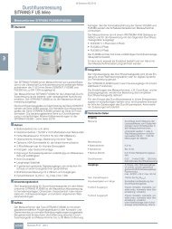
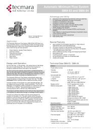
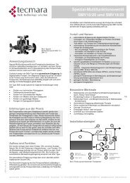
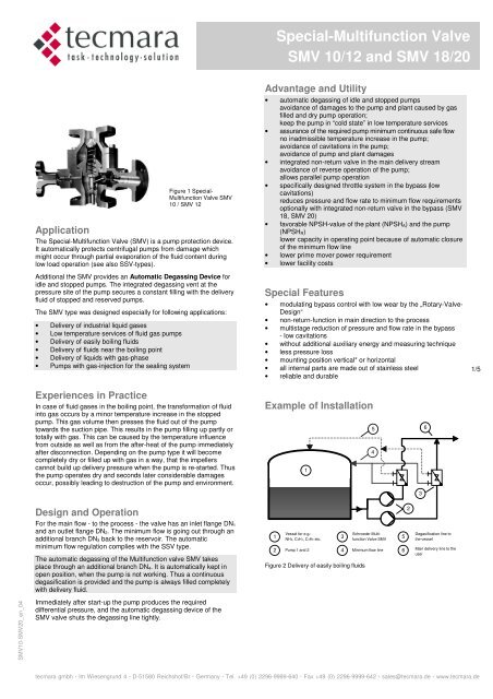
Figure 1 <strong>Special</strong>-<br />
<strong>Multi</strong>function <strong>Valve</strong> SMV<br />
10 / SMV 12<br />
Application<br />
The <strong>Special</strong>-<strong>Multi</strong>function <strong>Valve</strong> (SMV) is a pump protection <strong>de</strong>vice.<br />
It automatically protects centrifugal pumps from damage which<br />
might occur through partial evaporation of the fluid content during<br />
low load operation (see also SSV-types).<br />
Additional the SMV provi<strong>de</strong>s an Automatic Degassing Device for<br />
idle <strong>and</strong> stopped pumps. The integrated <strong>de</strong>gassing vent at the<br />
pressure site of the pump secures a constant filling with the <strong>de</strong>livery<br />
fluid of stopped <strong>and</strong> reserved pumps.<br />
The SMV type was <strong>de</strong>signed especially for following applications:<br />
• Delivery of industrial liquid gases<br />
• Low temperature services of fluid gas pumps<br />
• Delivery of easily boiling fluids<br />
• Delivery of fluids near the boiling point<br />
• Delivery of liquids with gas-phase<br />
• Pumps with gas-injection for the sealing system<br />
Advantage <strong>and</strong> Utility<br />
• automatic <strong>de</strong>gassing of idle <strong>and</strong> stopped pumps<br />
avoidance of damages to the pump <strong>and</strong> plant caused by gas<br />
filled <strong>and</strong> dry pump operation;<br />
keep the pump in “cold state” in low temperature services<br />
• assurance of the required pump minimum continuous safe flow<br />
no inadmissible temperature increase in the pump;<br />
avoidance of cavitations in the pump;<br />
avoidance of pump <strong>and</strong> plant damages<br />
• integrated non-return valve in the main <strong>de</strong>livery stream<br />
avoidance of reverse operation of the pump;<br />
allows parallel pump operation<br />
• specifically <strong>de</strong>signed throttle system in the bypass (low<br />
cavitations)<br />
reduces pressure <strong>and</strong> flow rate to minimum flow requirements<br />
optionally with integrated non-return valve in the bypass (SMV<br />
18, SMV 20)<br />
• favorable NPSH-value of the plant (NPSH A) <strong>and</strong> the pump<br />
(NPSH R)<br />
lower capacity in operating point because of automatic closure<br />
of the minimum flow line<br />
• lower prime mover power requirement<br />
• lower facility costs<br />
<strong>Special</strong> Features<br />
• modulating bypass control with low wear by the „Rotary-<strong>Valve</strong>-<br />
Design“<br />
• non-return-function in main direction to the process<br />
• multistage reduction of pressure <strong>and</strong> flow rate in the bypass<br />
- low cavitations<br />
• without additional auxiliary energy <strong>and</strong> measuring technique<br />
• less pressure loss<br />
• mounting position vertical* or horizontal<br />
• all internal parts are ma<strong>de</strong> out of stainless steel<br />
• reliable <strong>and</strong> durable<br />
1/5<br />
Experiences in Practice<br />
In case of fluid gases in the boiling point, the transformation of fluid<br />
into gas occurs by a minor temperature increase in the stopped<br />
pump. This gas volume then presses the fluid out of the pump<br />
towards the suction pipe. This results in the pump filling up partly or<br />
totally with gas. This can be caused by the temperature influence<br />
from outsi<strong>de</strong> as well as from the after-heat of the pump immediately<br />
after disconnection. Depending on the pump type it will become<br />
completely dry or filled up with gas in a way, that the impellers<br />
cannot build up <strong>de</strong>livery pressure when the pump is re-started. Thus<br />
the pump operates dry <strong>and</strong> seconds later consi<strong>de</strong>rable damages<br />
occur, possibly leading to <strong>de</strong>struction of the pump <strong>and</strong> environment.<br />
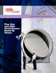
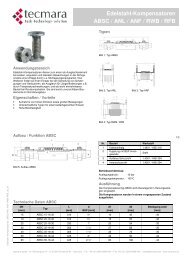
Example of Installation<br />
5<br />
4<br />
1<br />
6<br />
3<br />
Design <strong>and</strong> Operation<br />
For the main flow - to the process - the valve has an inlet flange DN 1<br />
<strong>and</strong> an outlet flange DN 2. The minimum flow is going out through an<br />
additional branch DN 3 back to the reservoir. The automatic<br />
minimum flow regulation complies with the SSV type.<br />
The automatic <strong>de</strong>gassing of the <strong>Multi</strong>function valve SMV takes<br />
place through an additional branch DN 4. It is automatically kept in<br />
open position, when the pump is not working. Thus a continuous<br />
<strong>de</strong>gasification is provi<strong>de</strong>d <strong>and</strong> the pump is always filled completely<br />
with <strong>de</strong>livery fluid.<br />
1<br />
2<br />
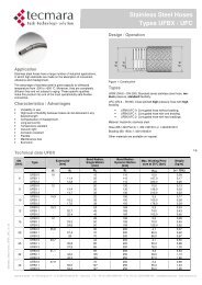
Vessel for e.g.:<br />
NH3, C2H4, C3H6 etc.<br />
Pump 1 <strong>and</strong> 2<br />
Figure 2 Delivery of easily boiling fluids<br />
3<br />
Schroe<strong>de</strong>r <strong>Multi</strong>function<br />
<strong>Valve</strong> SMV<br />
4 Minimum flow line 6<br />
5<br />
2<br />
Degasification line to<br />
the vessel<br />
Main <strong>de</strong>livery line to the<br />
user<br />
<strong>SMV10</strong>-<strong>SMV20</strong>_en_04<br />
Immediately after start-up the pump produces the required<br />
differential pressure, <strong>and</strong> the automatic <strong>de</strong>gassing <strong>de</strong>vice of the<br />
SMV valve shuts the <strong>de</strong>gassing line tightly.<br />
tecmara gmbh . Im Wiesengrund 4 . D-51580 Reichshof/Br . Germany . Tel. +49 (0) 2296-9999-640 . Fax +49 (0) 2296-9999-642 . sales@tecmara.<strong>de</strong> . www.tecmara.<strong>de</strong>
<strong>Special</strong>-<strong>Multi</strong>function <strong>Valve</strong><br />
SMV 10/12 <strong>and</strong> SMV 18/20<br />
Technical Data SMV 10/12 <strong>and</strong> SMV 18/20<br />
Medium<br />
Fluids without solids up to 15% gas phase<br />
Viscosity<br />
Temperature<br />
Engineering Specification<br />
Nominal width DN<br />
≤ 150 cSt<br />
-200 °C up to +300 °C*<br />
-330 °F up to +572 °F*<br />
• main direction 25 up to 300 mm; (1“ up to 12“)*<br />
• bypass 15 up to 150 mm (0,5“ up to 6“)*<br />
• automatic <strong>de</strong>gassing 15 or 25 mm (0,5“ or 1“)*<br />
Pressure rate PN 10 up to PN 320*<br />
ANSI 150 up to ANSI 2500 lbs*<br />
Bypass control<br />
modulating with throttle or non-return<br />
valve<br />
Material casing parts 1.0460 (A105)* ASME in ()<br />
1.0566 (A350-LF2);<br />
1.4301 (A182-F304);<br />
1.4541 (A276-321);<br />
1.4571 (A276-316TI);<br />
1.4404 (A182-F316L);<br />
1.4462 (A182-F51);<br />
further materials by request<br />
Material internals<br />
Connection<br />
Mounting position<br />
Operating Condition<br />
Pressure difference<br />
between inlet (DN 1) <strong>and</strong><br />
Bypass branch (DN 3)<br />
Flow rate main direction<br />
Flow rate bypass<br />
Flow velocity<br />
Pressure loss in the valve<br />
(applied to main flow)<br />
* st<strong>and</strong>ard version, more by request<br />
stainless steel*<br />
Flanges according to DIN / ANSI*<br />
Sealing <strong>and</strong> connection parts are not<br />
scope of supply<br />
vertical* or horizontal<br />
max. 180 bar (40 bar SMV12/20)<br />
max. 2600 psi (580 psi SSV20/12)<br />
5 m³/h up to 2000 m³/h*<br />
22 USgpm up to 8800 USgpm*<br />
up to 630 m³/h* (2775 USgm)*<br />
35%, max. 50% of main flow rate is<br />
advised*<br />
max. 10 m/s (flange)<br />
0,5 bar (low pressure)<br />
up to 1,3 bar (high pressure)<br />
Design<br />
The construction is according to specification AD 2000 <strong>and</strong><br />
particularly to EN 13445. As per Pressure Equipment Directive<br />
97/23 EC the products are provi<strong>de</strong>d with the CE marking <strong>and</strong> the<br />
Declaration of Conformity. Certified according to the Module H1<br />
(Pres-sure Equipment Directive 97/23 EC) all dangerous material<br />
classes of category 1 to 4 are covered.<br />
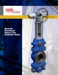
Installation <strong>and</strong> Connection<br />
The SMV is produced <strong>and</strong> tested only for the or<strong>de</strong>red data<br />
according the customer data sheet. Following points have to be<br />
allu<strong>de</strong>d:<br />
• Mounting direct on the pump discharge branch (advised)<br />
• Pipes have to be connected free of stress, without offset,<br />
mismatch or longitudinal shifting<br />
• The pipe system must be cleaned <strong>and</strong> free of soiling<br />
• Installation has to be in the or<strong>de</strong>red mounting position<br />
• The <strong>de</strong>gassing pipe has to go upward constantly <strong>and</strong> without<br />
any hollow<br />
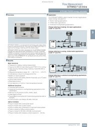
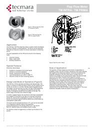
• To maintain the valve <strong>and</strong> to calm down the flow a piece of<br />
straight pipe with a length of 1 meter (40”) has to be installed<br />
at the bypass branch DN 3 <strong>and</strong> at the outlet branch DN 2<br />
• The bypass pipe has to be filled with medium anytime<br />
• The supplied installation <strong>and</strong> operating instructions has to be<br />
followed<br />
DN2<br />
DN1<br />
Right!<br />
admissible!<br />
DN2<br />
DN1<br />
False!<br />
Figure 3 Mounting with straight pipe piece<br />
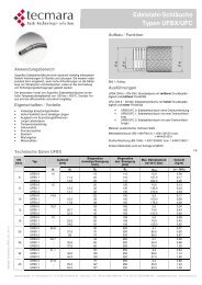
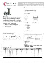
Q<br />
q2<br />
q3<br />
DN 4<br />
SMV<br />
DN 3<br />
not admissible!<br />
Degassing<br />
branch<br />
Main Pump<br />
Booster Pump<br />
DN 2<br />
DN 1<br />
not admissible!!<br />
Qmin<br />
q1<br />
Automatic Bypass<br />
Branch with throttle<br />
(Type SMV 10/12)<br />
<strong>and</strong> optional with<br />
non-return valve<br />
(Type SMV 18/20)<br />
DN2<br />
DN1<br />
Suction<br />
Tank<br />
False!<br />
Q<br />
2/5<br />
Figure 4 Bypass Return with automatic <strong>de</strong>gassing <strong>de</strong>vice<br />
<strong>SMV10</strong>-<strong>SMV20</strong>_en_04<br />
tecmara gmbh . Im Wiesengrund 4 . D-51580 Reichshof/Br . Germany . Tel. +49 (0) 2296-9999-640 . Fax +49 (0) 2296-9999-642 . sales@tecmara.<strong>de</strong> . www.tecmara.<strong>de</strong>
<strong>Special</strong>-<strong>Multi</strong>function <strong>Valve</strong><br />
SMV 10/12 <strong>and</strong> SMV 18/20<br />
Note of Application<br />
The operator of these fittings is responsible for suitability, proper<br />
use <strong>and</strong> corrosion resistance of the used materials with regard to<br />
the used fluid. It must be ensured that the materials selected for the<br />
fitting parts in contact with the medium are suitable for the used<br />
process media. The fitting may only be used for the application<br />
specified in the operating instructions <strong>and</strong> the data sheets. Provi<strong>de</strong><br />
a touch guard for surface temperatures of < -10 °C or > +50 °C.<br />
This touch guard must be <strong>de</strong>signed in a way that the max. allowable<br />
ambient temperature on the unit is not excee<strong>de</strong>d. Before replacing<br />
the valve, check that the unit is free of hazardous media <strong>and</strong><br />
pressures.<br />
Marking of the <strong>Valve</strong><br />
The <strong>Special</strong>-<strong>Multi</strong>function <strong>Valve</strong> has the following name plate with<br />
all relevant valve data.<br />
Designation of the <strong>Valve</strong>s<br />
The <strong>de</strong>signation of the valve specifies the type, nominal width <strong>and</strong><br />
pressure rate, the flange sizes <strong>and</strong> the mounting position.<br />
Example:<br />
S M V 1 0 - 5 0 / 1 6 0 - 50 / 50 / 15 / 15- 1<br />
S M V 1 0 - 2 “ ANSI900 - 2 / 2 / 0,5 / 0,5- 1<br />
<strong>Valve</strong> type<br />
with throttles in bypass 10<br />
with throttles in bypass 12<br />
with non-return valve<br />
in the bypass 18<br />
with non-return valve<br />
in the bypass 20<br />
<strong>Valve</strong> size<br />
DN 50 mm 50<br />
DN 2“ (ANSI) 2“<br />
Pressure rate<br />
160 bar 160<br />
900 lbs. (ANSI) ANSI900<br />
Flange sizes<br />
inlet DN 1 50 mm 50<br />
inlet DN 1 2“ (ANSI) 2<br />
outlet DN 2 50 mm 50<br />
outlet DN 2 2“ (ANSI) 2<br />
bypass DN 3 15 mm 15<br />
bypass DN 3 0,5“ (ANSI) 0,5<br />
<strong>de</strong>gassing branch DN 4 15 mm 15<br />
<strong>de</strong>gassing branch DN 4 0,5“ (ANSI) 0,5<br />
mounting (applied to main flow)<br />
vertical 1<br />
horizontal 2<br />
Figure 5 Name plate mounted to the fitting<br />
Accessories<br />
The h<strong>and</strong> operating branch with multiport-throttle is fitted at the<br />
casing below the cone seat <strong>and</strong> serves to pass off the minimum flow<br />
via a h<strong>and</strong>-operated valve combination. We recommend the branch<br />
for protection of the internal bypass parts at extreme operating<br />
conditions, e.g. at high differential pressures <strong>and</strong> frequent operation<br />
in the range of bypass flow as well as for filling <strong>and</strong> start-up of the<br />
plant.<br />
Start-Up-Trim (SUT) substitutes the bypass valve head during<br />
cleaning <strong>and</strong> start-up of plants <strong>and</strong> therefore spares the<br />
sophisticated regulating parts (optional, permanently open bypass<br />
outlet). Also usable instead of the h<strong>and</strong> operating branch.<br />
Warm-up branch, pressure gauge branch, draining branch etc. can<br />
be provi<strong>de</strong>d, if required.<br />
The pressure <strong>de</strong>vice SPD avoids cavitations <strong>and</strong> flashing in piping.<br />
The function corresponds to a variable throttle which adjusts oneself<br />
to the flow rate.<br />
The damping valve SRV will be applied to absorb pressure shocks<br />
during recurrent on/off operation e.g. for <strong>de</strong>scaling facilities at steel<br />
mills. The SRV has to be mounted direct to the AR-<strong>Valve</strong>.<br />
3/5<br />
SMV 12, SMV 20<br />
The type SMV 12 resp. SMV 20 corresponds technical with the<br />
SMV 10 resp. SMV 18 <strong>and</strong> will be supplied with a larger bypass.<br />
This is required for larger bypass flows up to 40 bar differential<br />
pressure. The choice will be done factory-ma<strong>de</strong>.<br />
<strong>SMV10</strong>-<strong>SMV20</strong>_en_04<br />
tecmara gmbh . Im Wiesengrund 4 . D-51580 Reichshof/Br . Germany . Tel. +49 (0) 2296-9999-640 . Fax +49 (0) 2296-9999-642 . sales@tecmara.<strong>de</strong> . www.tecmara.<strong>de</strong>
<strong>Special</strong>-<strong>Multi</strong>function <strong>Valve</strong><br />
SMV 10/12 <strong>and</strong> SMV 18/20<br />
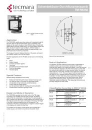
Parts List SMV 10/12 with Throttles<br />
Part-# Designation Materials<br />
1 Lower body<br />
2 Upper body<br />
3 Cone<br />
4 Cone gui<strong>de</strong><br />
10 Bypass branch<br />
15 Throttle<br />
26 Degassing Branch<br />
27 Degassing <strong>Valve</strong><br />
60 Bypass <strong>Valve</strong> Head, compelte<br />
78.1 O-Ring<br />
78.2 O-Ring<br />
78.3 O-Ring<br />
78.4 O-Ring<br />
78.5 O-Ring<br />
91.1 Socket screw<br />
91.2 Socket screw<br />
95.1 Coil spring<br />
95.4 Coil spring<br />
according to<br />
operating<br />
conditions<br />
<strong>and</strong> valid<br />
st<strong>and</strong>ards<br />
Wear <strong>and</strong> Spare Parts SMV 10/12<br />
Bypass <strong>Valve</strong> Head<br />
Bypass <strong>Valve</strong> Head, complete Part-# 60<br />
Throttle in the Bypass Branch<br />
Throttle Part-# 15<br />
O-Ring Part-# 78.2<br />
Single Spare Parts<br />
Degassing <strong>Valve</strong> Part-# 27<br />
O-Ring Part-# 78.1<br />
O-Ring Part-# 78.2<br />
O-Ring Part-# 78.3<br />
O-Ring Part-# 78.4<br />
O-Ring Part-# 78.5<br />
Coil spring Part-# 95.1<br />
Coil spring Part-# 95.4<br />
With reservation to changes<br />
4/5<br />
<strong>SMV10</strong>-<strong>SMV20</strong>_en_04<br />
Figure 6 SMV 10/12 with multistage pressure <strong>and</strong> flow reduction in the bypass<br />
tecmara gmbh . Im Wiesengrund 4 . D-51580 Reichshof/Br . Germany . Tel. +49 (0) 2296-9999-640 . Fax +49 (0) 2296-9999-642 . sales@tecmara.<strong>de</strong> . www.tecmara.<strong>de</strong>
<strong>Special</strong>-<strong>Multi</strong>function <strong>Valve</strong><br />
SMV 10/12 <strong>and</strong> SMV 18/20<br />
Parts List SMV 18/20 with Non-Return<br />
<strong>Valve</strong> in the Bypass<br />
Part-# Designation Materials<br />
1 Lower body<br />
2 Upper body<br />
3 Cone<br />
4 Cone gui<strong>de</strong><br />
10 Bypass Branch<br />
16 Throttle<br />
17 <strong>Valve</strong><br />
26 Degassing Branch<br />
27 Degassing <strong>Valve</strong><br />
60 Bypass <strong>Valve</strong> Head, compelte<br />
78.1 O-Ring<br />
78.2 O-Ring<br />
78.3 O-Ring<br />
78.4 O-Ring<br />
78.5 O-Ring<br />
91.1 Socket screw<br />
91.2 Socket screw<br />
95.1 Coil spring<br />
95.3 Coil spring<br />
95.4 Coil spring<br />
according to<br />
operating<br />
conditions<br />
<strong>and</strong> valid<br />
st<strong>and</strong>ards<br />
Wear <strong>and</strong> Spare Parts SMV 18/20<br />
Bypass <strong>Valve</strong> Head<br />
Bypass <strong>Valve</strong> Head, complete Part-# 60<br />
Non-Return Vale, complete<br />
Throttle Part-# 16<br />
<strong>Valve</strong> Part-# 17<br />
O-Ring Part-# 78.4<br />
Coil spring Part-# 95.3<br />
Single Spare Parts<br />
Degassing <strong>Valve</strong> Part-# 27<br />
O-Ring Part-# 78.1<br />
O-Ring Part-# 78.2<br />
O-Ring Part-# 78.3<br />
O-Ring Part-# 78.4<br />
O-Ring Part-# 78.5<br />
Coil spring Part-# 95.1<br />
Coil spring Part-# 95.4<br />
5/5<br />
<strong>SMV10</strong>-<strong>SMV20</strong>_en_04<br />
Figure 7 SSV 18/20 with integrated non-return valve <strong>and</strong> multistage pressure <strong>and</strong> flow reduction in the bypass<br />
tecmara gmbh . Im Wiesengrund 4 . D-51580 Reichshof/Br . Germany . Tel. +49 (0) 2296-9999-640 . Fax +49 (0) 2296-9999-642 . sales@tecmara.<strong>de</strong> . www.tecmara.<strong>de</strong>