ECE 496Y Project Proposal (Draft B) Meeting Form - Images Festival
ECE 496Y Project Proposal (Draft B) Meeting Form - Images Festival
ECE 496Y Project Proposal (Draft B) Meeting Form - Images Festival

You also want an ePaper? Increase the reach of your titles
YUMPU automatically turns print PDFs into web optimized ePapers that Google loves.
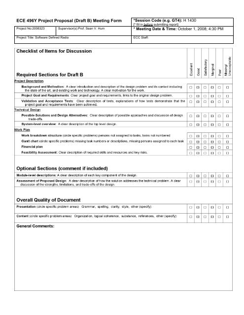
<strong>ECE</strong> <strong>496Y</strong> <strong>Project</strong> <strong>Proposal</strong> (<strong>Draft</strong> B) <strong>Meeting</strong> <strong>Form</strong> *Session Code (e.g. GT4): H 1430<br />
[* fill in before submitting report]<br />
<strong>Project</strong> No:2008323 Supervisor(s):Prof. Sean V. Hum * <strong>Meeting</strong> Date & Time: October 1, 2008; 4:30 PM<br />
<strong>Project</strong> Title: Software Defined Radio<br />
ECC Staff:
The Edward S. Rogers Sr. Department of<br />
Electrical and Computer Engineering<br />
University of Toronto<br />
<strong>ECE</strong><strong>496Y</strong> Design <strong>Project</strong> Course<br />
Group <strong>Project</strong> <strong>Proposal</strong> (<strong>Draft</strong> B)<br />
Title: Software Defined Radio<br />
<strong>Project</strong> I.D.#: 2008323<br />
Team members:<br />
Name:<br />
Email:<br />
(Select one member to<br />
be the main contact.<br />
Alp Kucukelbir 994422629<br />
alp.kucukelbir@utoronto.ca<br />
Mark with ‘*’) *Rajat Mark Grover 995705241 mark.grover@utoronto.ca<br />
Tyler de Witt 990759292<br />
tyler.dewitt@utoronto.ca<br />
Supervisor:<br />
Prof. Sean V. Hum<br />
Section #: 5<br />
Course Administrator: Prof. Hamid Timorabadi<br />
Date: September 25, 2008
Team Phoenix – de Witt, Grover, Kucukelbir<br />
<strong>Project</strong> <strong>Proposal</strong> – <strong>Draft</strong> B<br />
Executive Summary<br />
The Software Defined Radio (SDR) movement aims to bring reconfigurable, adaptive solutions<br />
to an otherwise hardware-dominated, rigid world of communications. SDR transmitters<br />
and receivers have attracted much interest from professional and amateur organizations,<br />
thereby encouraging a strong development. Most amateur implementations<br />
of SDR systems are based on a Personal Computer and low-cost radio frequency (RF)<br />
equipment. Our goal is to design and build a stand-alone SDR receiver capable of receiving<br />
a variety of RF signals using different modulation schemes. Various other alternate<br />
designs are considered within, and contrasted to our own. A preliminary feasibility and<br />
risk analysis is also conducted, aiming to elucidate any potential problems in the early<br />
stage of development. Also included is a work breakdown structure and a Gantt chart.<br />
Finally, a financial plan is presented for budgeting purposes.<br />
<strong>ECE</strong>496 Page 1 of 13
Team Phoenix – de Witt, Grover, Kucukelbir<br />
<strong>Project</strong> <strong>Proposal</strong> – <strong>Draft</strong> B<br />
Contents<br />
1 <strong>Project</strong> Description 3<br />
1.1 Background and Motivation . . . . . . . . . . . . . . . . . . . . . . . . . . . . 3<br />
1.2 <strong>Project</strong> Goal . . . . . . . . . . . . . . . . . . . . . . . . . . . . . . . . . . . . . 5<br />
1.3 <strong>Project</strong> Requirements . . . . . . . . . . . . . . . . . . . . . . . . . . . . . . . . 5<br />
1.3.1 Functional Requirements . . . . . . . . . . . . . . . . . . . . . . . . . 5<br />
1.3.2 Objectives . . . . . . . . . . . . . . . . . . . . . . . . . . . . . . . . . . 6<br />
1.3.3 Constraints . . . . . . . . . . . . . . . . . . . . . . . . . . . . . . . . . 6<br />
1.4 Validation and Acceptance Tests . . . . . . . . . . . . . . . . . . . . . . . . . 6<br />
1.4.1 Validation Tests . . . . . . . . . . . . . . . . . . . . . . . . . . . . . . . 6<br />
1.4.2 Acceptance Tests . . . . . . . . . . . . . . . . . . . . . . . . . . . . . . 7<br />
2 Technical Design 8<br />
2.1 Possible Solutions and Design Alternatives . . . . . . . . . . . . . . . . . . . 8<br />
2.1.1 Alternative A . . . . . . . . . . . . . . . . . . . . . . . . . . . . . . . . 8<br />
2.1.2 Alternative B . . . . . . . . . . . . . . . . . . . . . . . . . . . . . . . . 9<br />
2.1.3 Alternative C . . . . . . . . . . . . . . . . . . . . . . . . . . . . . . . . 9<br />
3 Work Plan 10<br />
3.1 Work Breakdown Structure . . . . . . . . . . . . . . . . . . . . . . . . . . . . 10<br />
3.2 Gantt Chart . . . . . . . . . . . . . . . . . . . . . . . . . . . . . . . . . . . . . 10<br />
3.3 Financial Plan . . . . . . . . . . . . . . . . . . . . . . . . . . . . . . . . . . . . 11<br />
3.3.1 Contingency . . . . . . . . . . . . . . . . . . . . . . . . . . . . . . . . . 11<br />
3.4 Feasibility Assessment . . . . . . . . . . . . . . . . . . . . . . . . . . . . . . . 12<br />
3.4.1 Skills and Resources . . . . . . . . . . . . . . . . . . . . . . . . . . . . 12<br />
3.4.2 Required Equpiment . . . . . . . . . . . . . . . . . . . . . . . . . . . . 12<br />
3.5 Risk Assessment . . . . . . . . . . . . . . . . . . . . . . . . . . . . . . . . . . . 12<br />
<strong>ECE</strong>496 Page 2 of 13
Team Phoenix – de Witt, Grover, Kucukelbir<br />
<strong>Project</strong> <strong>Proposal</strong> – <strong>Draft</strong> B<br />
1 <strong>Project</strong> Description<br />
1.1 Background and Motivation<br />
What is Software Defined Radio?<br />
Simply put Software Defined Radio is defined as: “Radio in which some or all of the<br />
physical layer functions are software defined. A radio is any kind of device that wirelessly<br />
transmits or receives signals in the radio frequency (RF) part of the electromagnetic<br />
spectrum to facilitate the transfer of information. In today’s world, radios exist in a multitude<br />
of items such as cell phones, computers, car door openers, vehicles, and televisions.”<br />
— from SDRforum.org.<br />
What is the benefit of a SDR receiver?<br />
“A SDR receiver would allow provide end-users with access to ubiquitous wireless communications<br />
– enabling them to communicate with whomever they need, whenever they<br />
need to and in whatever manner is appropriate.” — from SDRforum.org.<br />
Other benefits include:<br />
1. Upgradeability – a new modulation scheme can be implemented and downloaded to<br />
the receiver.<br />
2. Adaptability/Versatility – a single device that can operate on a large spectrum through<br />
narrowband and/or wideband operation without the need for specific/costly hardware.<br />
<strong>ECE</strong>496 Page 3 of 13
Team Phoenix – de Witt, Grover, Kucukelbir<br />
<strong>Project</strong> <strong>Proposal</strong> – <strong>Draft</strong> B<br />
Who are the stakeholders and how does SDR benefit them?<br />
1. Radio equipment developers/manufacturers<br />
• Creation of “lateral” layers of portability will greatly reduce development across<br />
multiple “radio products” – e.g. same modulation scheme, different frequency<br />
band or different platform<br />
2. Radio service/network providers<br />
• Reduction in operational costs and upgradability within radio networks. Less<br />
hardware based major investments and more flexible, “future-looking” approaches<br />
in day-to-day implementations<br />
3. The end-user of a SDR system<br />
• Communication in whatever method/manner is best suitable, and compatibility<br />
with legacy standards – all in one<br />
4. Governments, Public safety alliances and frequency allocation organizations<br />
• Potential free-up of frequency bands, and allocation of wide-band “free-space”<br />
for frequency sensitive applications<br />
Where are the applications of SDR?<br />
1. Immediate applications include: Military Joint Tactical Radio Systems (JTRS), and<br />
amateur short-wave radio systems.<br />
2. Goals include: commercial radio systems (radio/cellular/wireless ad-hoc networks),<br />
frequency sensitive platforms.<br />
<strong>ECE</strong>496 Page 4 of 13
Team Phoenix – de Witt, Grover, Kucukelbir<br />
<strong>Project</strong> <strong>Proposal</strong> – <strong>Draft</strong> B<br />
Why is Team Phoenix motivated?<br />
1. We are motivated to develop a standalone software defined radio, to demonstrate<br />
the practicality and adaptability of software-reconfigurable systems emerging in<br />
communications. We are inspired by the idea of “Plug-and-Play” practicality in<br />
complex communication systems.<br />
1.2 <strong>Project</strong> Goal<br />
This project aims to develop a general purpose, reconfigurable standalone SDR platform.<br />
Electronically, the device shall change function to demodulate arbitrary RF signals received<br />
from a selectable spectrum. The device is meant to be a portable, general purpose<br />
tool to act effectively as a ‘swiss-army knife’ radio receiver. To demonstrate reconfigurability,<br />
at least 2 different demodulation schemes shall be implemented for the platform.<br />
1.3 <strong>Project</strong> Requirements<br />
1.3.1 Functional Requirements<br />
RECONFIGURABILITY:<br />
• The device shall demodulate at least two modulation schemes using software signal<br />
processing techniques. Specifically the following shall be demonstrated:<br />
1. Reception, demodulation, and output of commercial FM broadcasts.<br />
2. Reception, and display of text messages transmitted using digital modulation<br />
via a test RF transmitter.<br />
<strong>ECE</strong>496 Page 5 of 13
Team Phoenix – de Witt, Grover, Kucukelbir<br />
<strong>Project</strong> <strong>Proposal</strong> – <strong>Draft</strong> B<br />
PORTABILITY:<br />
• The device shall be small and light enough for a single person to carry, setup, and<br />
operate in a remote location in less than 10 minutes.<br />
1.3.2 Objectives<br />
RECONFIGURABILITY:<br />
• The device shall apply arbitrary demodulation schemes to carrier waves selectable<br />
over a wide electromagnetic spectrum.<br />
PORTABILITY:<br />
• The device shall be made to be as small and light as possible.<br />
1.3.3 Constraints<br />
• The receiver shall be smaller than 50 × 50 × 30 cm 3 .<br />
• The receiver shall not weigh more than 4 kilograms<br />
• The receiver shall not cost Team Phoenix more than $1500 CAD.<br />
1.4 Validation and Acceptance Tests<br />
1.4.1 Validation Tests<br />
RECONFIGURABILITY:<br />
Resources Needed: Receiver and two RF signals modulated differently in schemes supported<br />
by the receiver.<br />
Testing Procedure: Configure the receiver to receive each signal one at a time.<br />
<strong>ECE</strong>496 Page 6 of 13
Team Phoenix – de Witt, Grover, Kucukelbir<br />
<strong>Project</strong> <strong>Proposal</strong> – <strong>Draft</strong> B<br />
Verification Procedure: Analyze and compare the output to the expected output (a perceivable<br />
signal in case of an audio output, a decipherable message on the screen in<br />
case of a text output).<br />
Acceptance Level: Test passes if the audio signal is perceivable as the sent signal and if<br />
the text output is the same as the message sent.<br />
PORTABILITY:<br />
Resources Needed: Pre-programmed receiver and a source of power.<br />
Testing Procedure: Individual carries receiver to a different location and set it up.<br />
Verification Procedure: Analyze the receiver output and note the time taken for setup.<br />
Acceptance Level: Test passes if the receiver can receive the output to a perceivable extent<br />
and the project was setup in 10 minutes or less.<br />
1.4.2 Acceptance Tests<br />
GENERAL PURPOSE RECONFIGURABLE PLATFORM<br />
Resources Needed: Receiver and an arbitrarily modulated RF signal.<br />
Testing Procedure: Program the receiver to demodulate the new (arbitrary) modulation<br />
scheme. Ensure correct spectral selection on both receiver and transmitter.<br />
Verification Procedure: Analyze the output and compare to desired output.<br />
Acceptance Level: Test passes if the receiver output matches the expected out, fails otherwise.<br />
<strong>ECE</strong>496 Page 7 of 13
Team Phoenix – de Witt, Grover, Kucukelbir<br />
<strong>Project</strong> <strong>Proposal</strong> – <strong>Draft</strong> B<br />
2 Technical Design<br />
2.1 Possible Solutions and Design Alternatives<br />
The software radio will consist of three stages:<br />
1. Radio frequency stage to receive and amplify radio signals<br />
2. AD converter stage to convert radio signals to digital data<br />
3. Digital processing stage for demodulating signals<br />
The following solutions deal with the design alternatives for the three stages and methods<br />
of interfacing them. For each solution, we list pros and cons of each combination with<br />
reference to design parameters.<br />
2.1.1 Alternative A – General purpose PC interfaced to a consumer sound card acting<br />
as an AD converter, fed by an analog RF antenna/receiver.<br />
General purpose computer<br />
Pros: configurable, easy to test, IO peripherals present for control.<br />
Cons: not portable, less reliable due to reliance on operating system.<br />
Low speed data converter (sound card)<br />
Pros: simple and inexpensive<br />
Cons: small bandwidth avaiable to process (20khz), requires downmixing and tuning to<br />
be done by analog receiver<br />
<strong>ECE</strong>496 Page 8 of 13
Team Phoenix – de Witt, Grover, Kucukelbir<br />
<strong>Project</strong> <strong>Proposal</strong> – <strong>Draft</strong> B<br />
High performanced RF receiver and down mixer<br />
Pros: could be purchased, put out of the scope of the design<br />
Cons: requires more analog circuitry, less configurable, complex<br />
2.1.2 Alternative B – DSP development board interfaced to a high speed AD converter,<br />
fed by an RF antenna/receiver with simplified downmixing.<br />
Embedded DSP development board<br />
Pros: small, self contained, reliable<br />
Cons: requires external controls, more difficult to test<br />
High speed data converter board<br />
Pros: move bandwidth available (10s of Mhz), allows digital downmixing for tuning<br />
Cons: expensive<br />
RF receiver with simplified IF/downmixing stage<br />
Pros: RF downmixing stage simplified since AD converter can sample a larger spectrum<br />
2.1.3 Alternative C – Custom designed embedded system with onboard chips for DSP,<br />
AD conversion and RF downmixing, interfaced to an antenna.<br />
In this solution, the three stages are embedded on a single board.<br />
Pros: very small and portable, reliable<br />
Cons: large design effort, risky<br />
<strong>ECE</strong>496 Page 9 of 13
Team Phoenix – de Witt, Grover, Kucukelbir<br />
<strong>Project</strong> <strong>Proposal</strong> – <strong>Draft</strong> B<br />
Team Phoenix believes that Alternative B provides a good tradeoff between the constraints,<br />
objectives, and functional requirements defined for this project, and will develop<br />
a product within the framework described in Alternative B.<br />
3 Work Plan<br />
3.1 Work Breakdown Structure<br />
Figure 1: Work Breakdown Structure<br />
3.2 Gantt Chart<br />
A Gantt Chart is appended to the end of this document.<br />
<strong>ECE</strong>496 Page 10 of 13
Team Phoenix – de Witt, Grover, Kucukelbir<br />
<strong>Project</strong> <strong>Proposal</strong> – <strong>Draft</strong> B<br />
3.3 Financial Plan<br />
Please see Table 1 for a tabulated presentation of our financial plan.<br />
Table 1: Financial Plan<br />
Item Maximum Price Notes<br />
DSP Development<br />
$600 Possibility of borrowing lower<br />
Board<br />
end performance board from<br />
Communications Lab for $0<br />
High Speed A/D<br />
$300<br />
Converter<br />
PC/Laptop $0 Already owned<br />
RF Transmitter $50<br />
Misc Electrical<br />
$50<br />
Components<br />
Test Equpiment $0 Design Centre and Communications<br />
Lab<br />
$1000 Net Expense<br />
Contribution Amount Notes<br />
Design Centre Funding<br />
$300<br />
Team Contribution $300<br />
$600 Net Contribution<br />
−$400 NET DEFICIT<br />
3.3.1 Contingency<br />
A slightly lower performance DSP development board from the communications lab is<br />
available for $0. In the event that funding cannot be secured from the design centre, our<br />
team is prepared to absorb all expenses.<br />
<strong>ECE</strong>496 Page 11 of 13
Team Phoenix – de Witt, Grover, Kucukelbir<br />
<strong>Project</strong> <strong>Proposal</strong> – <strong>Draft</strong> B<br />
3.4 Feasibility Assessment<br />
3.4.1 Skills and Resources<br />
This project requires skills and knowledge in the areas of programming, DSP, digital<br />
design, antenna design and EM waves. Together, the team members have strong relevant<br />
coursework and/or background in these areas. Professor Hum specializes in antenna/radio<br />
design and will provide advice for the RF side. Practical information for<br />
DSP programming will be obtained from spec sheets, manuals, and the internet.<br />
3.4.2 Required Equpiment<br />
The key hardware items are available at estimated price of $900 or less. They are manufactured<br />
in large numbers and immediately available for purchase. Test equipment in the<br />
SF design centre will also be utilized throughout the project development.<br />
Example equipment breakdown<br />
TMS320C6455 DSP Starter Kit (DSK) $595<br />
ADS5525EVM 12-bit 170MSps $299<br />
3.5 Risk Assessment<br />
Software radio attempts to implement as much as possible through a digital embedded<br />
system. Most failures can be mitigated by moving a particularly onerous function to a different<br />
stage. This can be done by substituting a non custom component, or by marginally<br />
reducing the functionality of the overall system. The project is modular enough that the<br />
<strong>ECE</strong>496 Page 12 of 13
Team Phoenix – de Witt, Grover, Kucukelbir<br />
<strong>Project</strong> <strong>Proposal</strong> – <strong>Draft</strong> B<br />
different stages can be developed and tested independently, mitigating the risk of a difficulty<br />
halting the whole development process.<br />
A few key risks are summarized below:<br />
Risk: Difficulty in implementing a controllable RF receiver<br />
• The risk is due to the team members possessing the least amount of knowledge<br />
in RF circuitry, and the custom design required for reconfigurable RF functionality.<br />
Mitigation: Make use of a purchased FM receiver to tune and downmix the FM band<br />
to base-band. In this case, the radio will lose part of its reconfigurability, but the<br />
system will still meet its functional requirements. Yet the DSP facet of the project is<br />
not dependent on the RF receiver.<br />
Risk: Direct sampling of large bandwidth too much for DSP chip to process<br />
• The risk is due to the uncertainty in the DSP algorithms we will develop.<br />
Mitigation: Early testing will be performed on the development board. Failure will necessitate<br />
downsampling in the analog RF stage, or the introduction of an additional<br />
hardware module for dedicated digital downsampling.<br />
<strong>ECE</strong>496 Page 13 of 13