Structural Analysis of Replacement Knee Design - Ansys
Structural Analysis of Replacement Knee Design - Ansys
Structural Analysis of Replacement Knee Design - Ansys

You also want an ePaper? Increase the reach of your titles
YUMPU automatically turns print PDFs into web optimized ePapers that Google loves.
CASE STUDY<br />
<strong>Structural</strong> <strong>Analysis</strong> <strong>of</strong> <strong>Replacement</strong> <strong>Knee</strong> <strong>Design</strong><br />
DEPUY, A JOHNSON & JOHNSON COMPANY<br />
EXECUTIVE SUMMARY<br />
Challenge:<br />
To analyze two sizes <strong>of</strong> a<br />
replacement knee design at<br />
different angles <strong>of</strong> articulation<br />
Solution:<br />
Use ANSYS to analyze the design<br />
Benefits:<br />
Allowed DePuy to attain a good<br />
indication <strong>of</strong> the performance <strong>of</strong><br />
the product before testing<br />
Introduction<br />
DePuy is the oldest manufacturer <strong>of</strong> orthopaedic<br />
implants in the United States. The company was<br />
founded in 1895 when Revra DePuy, a salesman,<br />
revolutionized the fracture management industry<br />
by introducing wire splints to replace the<br />
makeshift wooden splints then in use for<br />
stabilizing fractures. DePuy is one <strong>of</strong> the world’s<br />
leading orthopaedic companies, with a reputation<br />
for innovation in new product development.<br />
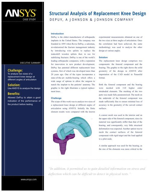
DePuy has patented different replacement knee<br />
systems, first <strong>of</strong> which was developed more than<br />
20 years ago. One <strong>of</strong> the types incorporates a<br />
state-<strong>of</strong>-the-art mobile-bearing which <strong>of</strong>fers a<br />
wide range <strong>of</strong> options to allow the surgeon to<br />
match the implant to the patients’ anatomy. The<br />
graphic to the right illustrates a typical replacement<br />
knee.<br />
Challenge<br />
The scope <strong>of</strong> this work was to analyze two sizes <strong>of</strong><br />
a replacement knee design at different angles <strong>of</strong><br />
articulation using ANSYS. Initially the finite<br />
element results were compared with the known<br />
experimental measurements obtained on one <strong>of</strong><br />
the two sizes at three angles <strong>of</strong> articulation. Once<br />
the correlation had been achieved, the same<br />
methodology was used to analyze the other<br />
design at various angles.<br />
Solution<br />
The replacement knee design comprises two<br />
components: the femoral component and the<br />
bearing. The graphic to the right shows the solid<br />
geometry <strong>of</strong> the design in ANSYS after<br />
importation <strong>of</strong> the CAD model in Parasolid<br />
format.<br />
Both the femoral component and the bearing<br />
were meshed with 3-D higher order<br />
tetrahedral elements. The meshing <strong>of</strong> the two<br />
parts was made fully parameterized. The mesh on<br />
the underside <strong>of</strong> the femoral component was<br />
made sufficiently fine to ensure minimal loss <strong>of</strong><br />
accuracy in the geometry <strong>of</strong> the curved contact<br />
surfaces.<br />
A coarser mesh was used in the interior and on<br />
the upper side <strong>of</strong> the femoral component, since its<br />
material was significantly stiffer than that <strong>of</strong> the<br />
bearing, and consequently, very little structural<br />
deformation was expected. Another option was to<br />
mesh the contact surfaces <strong>of</strong> the femoral<br />
component with rigid target and the load applied<br />
to a pilot node.<br />
A similar approach was used for the bearing, as<br />
the size <strong>of</strong> the elements was more critical in the<br />
“In addition, it permitted us to gain detailed information on stress and<br />
deflection which can be difficult to detect in physical tests.”<br />
www.ansys.com
CASE STUDY<br />
“This validation has allowed us to extend the application <strong>of</strong> this<br />
methodology to the evaluation <strong>of</strong> a range <strong>of</strong> new implant designs,<br />
providing feedback accurately and in a short timeframe.”<br />
contact region than other non-contacting<br />
surfaces. However, a mesh density even finer<br />
than that on the contact surfaces <strong>of</strong> the femoral<br />
component was desirable in the bearing to<br />
ensure a good resolution <strong>of</strong> the contact area and<br />
stresses. An indiscriminate refinement <strong>of</strong> the<br />
mesh on all the upper surfaces <strong>of</strong> the bearing<br />
proved to be computationally too expensive and<br />
a new meshing procedure was developed and<br />
tested by IDAC, a finite element analysis and<br />
computer-aided engineering consulting firm<br />
and the leading UK provider <strong>of</strong> ANSYS and<br />
<strong>Design</strong>Space s<strong>of</strong>tware.<br />
A preliminary contact analysis was first run<br />
with the original mesh density prescribed to the<br />
bearing, then the elements that were in contact<br />
with the femoral component were further<br />
refined for the subsequent solution. An example<br />
<strong>of</strong> this mesh is depicted in the figure on the<br />
right.<br />
The graphic above illustrates the stress<br />
distribution in contact area between the bearing<br />
and the femoral component. These stress<br />
distribution plots can be created in the ANSYS<br />
program for any point in time during the<br />
nonlinear solution.<br />
It was found that excessive geometric<br />
penetration at setup produced stress<br />
singularities and, therefore, the contact pair<br />
should be checked prior to the solution.<br />
Localized peak contact stresses also could be<br />
produced by the discretization <strong>of</strong> the otherwise<br />
smooth contact surfaces. The mesh refinement<br />
level for the elements in the vicinity <strong>of</strong> contact<br />
after the preliminary contact analysis may be<br />
increased, but at the expense <strong>of</strong> a longer solution<br />
time.<br />
Apart from the contact stresses, the total contact<br />
area was also an important result item. The total<br />
contact area was obtained from summing the<br />
areas <strong>of</strong> all contact elements showing partial or<br />
full contact. This generally leads to an<br />
overestimation <strong>of</strong> the actual contact area<br />
although it was considered insignificant given<br />
the high mesh density in the contact area.<br />
All <strong>of</strong> the analysis work described here was<br />
performed on Intel based personal computers<br />
running the ANSYS Revision 7.0 program.<br />
DePuy are users <strong>of</strong> ANSYS and the parametric<br />
models created here by IDAC have been supplied<br />
to DePuy for their engineers to perform<br />
further analyses and modifications in-house.<br />
Benefits<br />
James Brooks, a senior mechanical design<br />
engineer at DePuy, was impressed with the<br />
results <strong>of</strong> the study. “Following on from this<br />
study, and working with IDAC, a number <strong>of</strong> our<br />
own engineers have been able to do further<br />
comparisons <strong>of</strong> a new design against an existing<br />
product in various loading conditions. This has<br />
rapidly allowed us to get a good indication <strong>of</strong><br />
the performance <strong>of</strong> the product before testing.”<br />
Fiona Haig, a mechanical designer at DePuy,<br />
also adds, “IDAC’s macro allowed us to quickly<br />
and consistently replicate physical testing<br />
which would normally have taken weeks to<br />
undertake in our labs. In addition, it permitted<br />
us to gain detailed information on stress and<br />
deflection which can be difficult to detect in<br />
physical tests. The macro has proved an invaluable<br />
tool in the comparison and validation <strong>of</strong><br />
new implant designs as well as proving a<br />
highly effective learning aid for our core team<br />
<strong>of</strong> FEA users.”<br />
She continues. “The results achieved using<br />
IDAC’s analysis method closely correlated to<br />
the results <strong>of</strong> those physical tests previously<br />
undertaken in our labs. This validation has<br />
allowed us to extend the application <strong>of</strong> this<br />
methodology to the evaluation <strong>of</strong> a range <strong>of</strong><br />
new implant designs, providing feedback<br />
accurately and in a short timeframe.”<br />
www.ansys.com<br />
ANSYS, Inc.<br />
Southpointe<br />
275 Technology Drive<br />
Canonsburg, PA 15317<br />
USA<br />
ansysinfo@ansys.com<br />
Toll-Free:<br />
1.866.267.9724<br />
Toll-Free Mexico:<br />
001.866.267.9724<br />
ANSYS is registered in the U.S. Patent and Trademark Office.<br />
©2004 SAS IP, Inc., a wholly owned subsidiary <strong>of</strong> ANSYS Inc.<br />
All Rights Reserved.