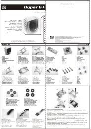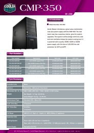
Manual - Cooler Master
Manual - Cooler Master
Manual - Cooler Master

You also want an ePaper? Increase the reach of your titles
YUMPU automatically turns print PDFs into web optimized ePapers that Google loves.
About Centurion<br />
"Centurion" represents quality of Discipline, Honor, Integrity & Loyalty.<br />
Now you don't have to be a Caesar to concord the digital world while<br />
feeling safe and proud..<br />
Index<br />
ABOUT CENTURION<br />
FEATURES<br />
SPECIFICATIONS<br />
DIAGRAM<br />
INSTALLATION<br />
REMOVING THE SIDE PANELS<br />
INSTALLING THE MOTHERBOARD<br />
TO INSTALL/ REPLACE THE POWER SUPPLY UNIT (PSU):<br />
INSTALLING DRIVES (CD-ROM, HDD, FDD, ETC.)<br />
REPLACING/INSTALLING THE CASE FANS<br />
1. Replacing / Installing the Rear Case Fan<br />
2. Replacing / Installing the Front Case Fans<br />
I/O FUNCTION PANEL INSTALLATION GUIDE<br />
01<br />
01<br />
01<br />
02<br />
04<br />
04<br />
04<br />
04<br />
05<br />
06<br />
06<br />
06<br />
06<br />
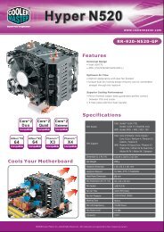
Features<br />
Discipline Asymmetrical shape layout.<br />
Royal Appearance Equipped with detailed high gloss front Alloy Shield.<br />
Protection Proactive heat resistant design for abusive ambient environment<br />
Integrity World famous solid assembly.<br />
Unique Armor Unique side panel mechanism provides great accessibility for<br />
installation & upgrade.<br />
Loyalty - Long lasting ownership.<br />
Tool-free assembly/disassembly for quick and maintenance or upgrade<br />
Special perforated screen design provides the superior airflow and maximum cooling<br />
performance; easy to clean and maintain<br />
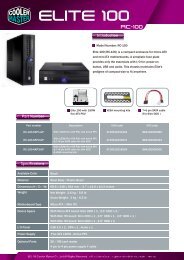
Specifications<br />
Dimensions: 480 mm x 202 mm x 435 mm (L x W x H)<br />
Material: Aluminum Bezel, SECC Chassis<br />
Main Board: ATX; 12"x 9.6"(30.5cm x 24.5cm)<br />
5.25" Drive Bay: 5 (Exposed)<br />
3.5" Drive Bay: 1 (Exposed), 4 (Hidden)<br />
Power Supply: Standard ATX PS2<br />
Front I/O: USB 2.0 x 2, IEEE 1394 (FireWire) x1, MIC x1, SPK x 1<br />
Cooling fan: One 80 x 80 x 25 mm Front Fan (intake)<br />
One 120 x 120 x 25 mm Rear Fan (exhaust)<br />
01
Diagram<br />
A. 3 Direction Diagram<br />
B.Exploded Picture<br />
02 03
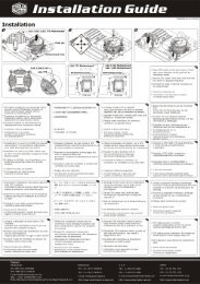
Installation<br />
Removing the Side Panels<br />
Step: Unscrew the side panel and remove it.<br />
Installing Drives (CD-ROM, HDD, FDD, etc.)<br />
Step:<br />
1. Remove the side panel and chassis front plate.<br />
2. Choose a 5.25 drive bay, unscrew the drive bay plate.<br />
3.Secure the chassis front plate.<br />
4.Place your device into it.<br />
Installing the Motherboard<br />
Step:<br />
1.Unscrew the side panel and remove it.<br />
2.Lay the chassis<br />
3.Locate the motherboard with the location of<br />
motherboard screw location.<br />
4.Secure the motherboard with suitable screws.<br />
To install/ replace the Power Supply Unit (PSU):<br />
Step:<br />
1.Locate the PSU at chassis PSU rack.<br />
2.Secure PSU with available screws.<br />
3.You finished installing the PSU.<br />
Slide CD-ROM, HDD, FDD into the 5.25 and 3.5 bay<br />
Fit the holder's hole complely<br />
Push plastic rail to the front part<br />
Press plastic lock down to lock<br />
04 05
Replacing/Installing The Case Fans<br />
1. Replacing / Installing the Rear Case Fan<br />
Step:<br />
1.Remove the side panel<br />
2.Remove four screws securing the exterior fan cover.<br />
3.Place the rear fan in position and secure it with four screws.<br />
The following illustration is a connection diagram for the Front Pane I/O cable.<br />
Doing so will damage the device. NEVER connect a 1394 cable to the USB<br />
connector.<br />
NEVER connect a USB cable to the 1394 connector. Doing so will damage the<br />
device.<br />
On some motherboards the connectors for 1394, USB and audio are not the<br />
same as the below drawing. Please check with your motherboard manual<br />
before install.<br />
2. Replacing / Installing the Front Case Fans<br />
Step:<br />
1.Remove the side panel<br />
2.Remove the front panel<br />
3.Remove four screws securing the exterior fan cover<br />
4.Place the rear fan in position and secure it with four screws<br />
Mother Board<br />
Front panel IEEE 1394 connector<br />
No Pin<br />
Front panel USB connector<br />
Cable<br />
IEEE 1394 Connector<br />
Pin<br />
USB Connector<br />
I/O function panel installation guide<br />
Please refer to the illustration on the section of USB,1394,Audio<br />
connector from motherboard user's manual , and please select the<br />
motherboard which use the same USB,1394,Audio standard as<br />
below . Otherwise , it will cause damage for user's device.<br />
No Pin<br />
Front panel audio connector<br />
No Pin<br />
Pin<br />
Front panel audio connector (BLACK)<br />
06 07