Download Manual - Ziamatic Corp
Download Manual - Ziamatic Corp
Download Manual - Ziamatic Corp

Create successful ePaper yourself
Turn your PDF publications into a flip-book with our unique Google optimized e-Paper software.
QUIC-CLAMP ® Hy d r a u l i c Ho s e Cl a m p<br />
Mo d e l 500-7<br />
ZICO ®<br />
2015PM1<br />
Pa r t s a n d In s t r u c t i o n Ma n u a l REV. 7-13-11<br />
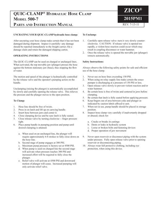
UNCRATING YOUR QUIC-CLAMP hydraulic hose clamp:<br />
After uncrating your hose clamp make certain that it has not been<br />
damaged during shipment. Inspect it carefully--any damage<br />
should be reported immediately to the freight carrier; file a<br />
damage claim and retain the damaged shipping carton.<br />
OPERATING INSTRUCTIONS<br />
The QUIC-CLAMP can be used on charged or uncharged lines.<br />
When activated, the top movable jaw (plunger) presses the hose<br />
against the bottom stationary jaw (base), thus stopping the flow<br />
of water.<br />
The motion and speed of the plunger is hydraulically controlled<br />
by the release valve and the operator's pumping action on the<br />
handle.<br />
Unclamping (raising the plunger) is automatically accomplished<br />
by slowly and carefully opening the release valve. This relieves<br />
the pressure and the plunger moves to the open position.<br />
To Clamp:<br />
1. Hose line should be free of twists.<br />
2. Press in on latch and lift up on carrying handle.<br />
3. Insert hose between jaws and center it.<br />
4. Close clamping device and be sure latch is fully seated.<br />
5. Close release valve by turning clockwise -- finger pressure<br />
tight.<br />
6. Place pump handle in pumping position and pump until<br />
desired clamping is attained.<br />
a. When used on an uncharged line, the plunger will<br />
require approximately 6-8 strokes to fully close down on<br />
the hose line.<br />
b. Second stage of pump engages at 300 PSI.<br />
c. Maximum pump pressure is factory-set at 4500 PSI.<br />
d. When pump is used on charged line the second stage<br />
will activate when pressure reaches 300 PSI and<br />
increased effort will be required to fully close the<br />
plunger.<br />
e. Relief valve will activate at 4500 PSI and downward<br />
motion of plunger will cease. Increased pumping will<br />
only activate relief valve.<br />
To Unclamp:<br />
1. Carefully open release valve--turn it very slowly counterclockwise.<br />
CAUTION: If release valve is opened too<br />
rapidly, a violent hose reaction could occur which may<br />
result in coupling disconnect or water hammer.<br />
2. Once the release valve is opened the movable jaw (plunger)<br />
retracts automatically.<br />
Safety Instructions:<br />
Always observe the following safety points for safe and efficient<br />
use of the hose clamp.<br />
1. Never use on hose lines exceeding 150 PSI.<br />
2. When using on relay supply line make certain the souce<br />
pumper is discharging at a pressure of 150 PSI or less.<br />
3. Open release valve slowly to prevent violent reaction and/or<br />
water hammer.<br />
4. Be certain hose is free of twists and centered in jaws before<br />
clamping.<br />
5. Be certain that latch is fully seated before applying pressure.<br />
6. Keep fingers out of area between yoke and plunger as<br />
indicated by caution labels affixed to unit.<br />
7. When not in use, pump handle should be placed in storage<br />
position.<br />
8. Inspect hose clamp very carefully if inadvertantly dropped<br />
or abused; check for:<br />
a. Cracks or breaks in castings<br />
b. Dents or leaks in hydraulic system<br />
c. Loose or broken bolts and fastening devices<br />
d. Proper operation of jaw movement<br />
9. Never open reservoir or disconnect piping with the system<br />
under pressure. Fully open release valve prior to opening<br />
reservoir or disconnecting piping.<br />
10. Always wear full protective clothing, including eye<br />
protection, when using this device.
ITEM<br />
NO.<br />
DESCRIPTION<br />
PART<br />
NUMBER<br />
PCS.<br />
REQUIRED<br />
1 Yoke Casting 2015-115-105 1<br />
2 Base Casting 2015-115-110 1<br />
3 Plunger Casting 2015-115-115 1<br />
4 Carrying Handle 2015-115-120 1<br />
5 Latch Casting 2015-115-125 1<br />
6 Two-Stage Pump/Reservoir (6A) 2015-115-130 1<br />
7 Hydraulic Ram 2015-115-135 1<br />
8 Tube Assembly & Fittings 2015-115-140 1<br />
9 1" Threaded Stud 2015-115-145 1<br />
10 Neoprene Base Pad 2015-115-150 1<br />
11 Pump Handle 2015-115-155 1<br />
12 5/16-18 x 3/4 Hex. Head Bolt 9010-103112 2<br />
13 5/16 ID Lock Washer 9014-203100 2<br />
14 1/4 x 1-3/4 Spring Pin 9040-102528 2<br />
15 1/4 x 5/8 Spring Pine 9040-002510 2<br />
16 Spring 2015-115-121 2<br />
17 1/2 x 3 Groove Pin 9045-005048 1<br />
18 1/2 x 1-3/4 Groove Pin 9045-005028 2<br />
19 Label "Turn to Close" 2015-115-126 1<br />
20 Label "Danger" 2015-115-131 2<br />
21 Label "Close Latch" 2015-115-136 1<br />
22 1/4-20 x 1-1/4 Pan Head Bolt 9010-212520 4<br />
23 1/4-20 ESNA Lock Nut 9013-172500 4<br />
26 Handle Grip 0000-000-115 1<br />
27 Label "Warning - to avoid" 2015-000-105 1<br />
31 Label, Metal, S/N 0000-000-105 1<br />
32 #4 Drive Screw 9120-101103 2<br />
S/N "Serial Number" stamped here<br />
prior to use of item 31<br />
33 90-Degree Elbow Adapter 3097-500-124 1<br />
34 1/4-20 x 3/4 Cup Pt Sock Screw 9010-382512 2<br />
35 5/16-18 x 1 Socket Head cap<br />
Screw<br />
9010-333116 2<br />
ITEM<br />
NO.<br />
MODEL 500-7<br />
MODEL 500-A-MB<br />
DESCRIPTION<br />
PART<br />
NUMBER<br />
PCS.<br />
REQUIRED<br />
1 Bracket Casting 2015-110-105 1<br />
2 Latch Casting 2015-110-110 1<br />
3 Spring Plunger 2015-110-115 1<br />
4 1/4-20 x 1-1/2" Flat Head Bolt 9010-152524 1<br />
5 1/4-20 Hex Head Nut 9013-172500 1<br />
6 Bushing 2015-110-120 1<br />
Page 2
Pump Operation:<br />
The low pressure first stage of the pump unloads at 300 PSI and<br />
delivers 2.35 cu. in. of oil per stroke of the handle. This provides<br />
fast ram approach.<br />
The high pressure second stage takes over when the pressure on<br />
the ram becomes more than 300 PSI and will develop pressure<br />
to the 4500 PSI maximum that this system is designed for. The<br />
second stage delivers .147 cu. in. of oil per full stroke of handle.<br />
NOTE: Always be sure that latch is full seated<br />
before applying pressure to the system.<br />
Valve Operation:<br />
The two-way pump is equipped with a two-way valve for use on<br />
single-acting rams. To extend a single-acting ram the valve knob<br />
should be turned in a clockwise direction. This closes the valve<br />
so that oil is pumped to the ram.<br />
To return the ram, the valve knob should be turned in a counterclockwise<br />
direction. This opens the valve and allows oil to flow<br />
back to the reservoir.<br />
Reservoir - Sealed:<br />
Reservoir capacity is 32 cu. in. When filled with one pint of<br />
hydraulic fluid the oil will occupy 28.875 cu. in. The reservoir is<br />
prefilled at the factory.<br />
To check the oil level:<br />
1. Make sure the release valve is in the open position to relieve<br />
all pressure on the system and return the oil to the reservoir.<br />
Ram will be in fully retracted position.<br />
2. Have the reservoir and filler cap face up.<br />
3. Remove the filler cap.<br />
4. Oil should be up to the bottom thread of the filler cap<br />
opening in the reservoir.<br />
The reservoir has a relief valve in the filler cap that is set at 15 to<br />
25 PSI. When the ram retracts, oil will vent to the atmosphere if<br />
more oil is contained in the system than the reservoir can handle.<br />
NOTE: Always wear full protective clothing, including<br />
eye protection, when working with the hose clamp.<br />
NOTE: the pump depends upon the hydraulic oil for<br />
lubrication of all moving parts and the use of improper<br />
fluids will result in serious damage to the unit.<br />
Troubleshooting:<br />
NOTE: Do not attempt to repair pump or ram if either<br />
one is not functioning properly. Return the complete<br />
unit to the factory or your nearest hydraulic service<br />
technician for repair.<br />
The only problem that can be field-corrected is low oil level. To<br />
correct, simply refill fluid capacity to required level (see<br />
Reservoir-Sealed). Low oil level will be indicated by ram not<br />
extending at normal rate or failure of the pump to reach full<br />
pressure.<br />
Hydraulic Connections:<br />
APPLIES TO HYDRAULIC RAM<br />
Single Acting -- Spring Return<br />
The QUIC-CLAMP hydraulic hose clamp has been inspected<br />
prior to shipment. All hydraulic connections should be free of<br />
dents or creases. If any loose connections or oil leaks are noted,<br />
call the factory before operating the clamp.<br />
NOTE: Do not attempt to repair pump or ram if either<br />
unit is not functioning properly. Return the complete<br />
unit to the factory or your nearest hydraulic service<br />
technician for repair.<br />
Hydraulic lines and fittings can act as restrictors when the<br />
cylinder or ram retracts slowing the hydraulic oil in its return<br />
to the pump. The restricting, or slowing, of the oil causes back<br />
pressure which will slow the cylinder or ram return. Return<br />
speed (retraction of plunger) will also vary because of ram<br />
condition and the oil's temperature and viscosity.<br />
Inspection:<br />
Make frequent visual inspections for the following problems:<br />
1. Cracked or damaged cylinder housing.<br />
2. Excessive wear, bending, or other damage to plunger, piston<br />
rod or cylinder housing.<br />
3. Cylinder becoming loose where threaded into yoke casting.<br />
4. Plunger becoming loose where threaded into end of piston<br />
rod.<br />
5. Leaking hydraulic fluid.<br />
6. Loose bolts.<br />
Any problems should be noted, the unit properly tagged, and not<br />
used until all repairs are completed.<br />
NOTE: Always wear full protective clothing, including<br />
eye protection, when working with the hose clamp.<br />
Important:<br />
1. Keep the piston rod clean at all times.<br />
2. Always center the hose line under the plunger and ram.<br />
3. When the cylinder is not in use keep the plunger fully<br />
retracted.<br />
NOTE: Clamp may not completely shut off flow of<br />
water. A clearance of approximnately 3/16" is allowed<br />
between the plunger and base to prevent damage to fire<br />
hose. If complete water stoppage is desired a thin piece<br />
of neoprene rubber may be placed on the base casting.<br />
Caution must be exercised to prevent hose damage.<br />
Page 3
SPECIFICATIONS:<br />
Weight: 53 lbs. -- shipping weight is 60 lbs.<br />
Dimensions: 18-1/2" L x 9" W x 20" H --<br />
(shipping container) 20-1/2" x 10-1/2" x 22"<br />
Pump: Hydraulic, two stage hand pump -- 10,000<br />
PSI capacity<br />
300 PSI second stage<br />
4500 PSI maximum -- factory-set and not to be changed in field<br />
Hydraulic ram: Single acting, spring return -- 10 ton capacity<br />
Limitations:<br />
Maximum working pressure of hose lines not to exceed 150 PSI<br />
Maximum hose diameter -- 5"<br />
Hydraulic fluid:<br />
AMS/OIL Superior Wisconsin Type AHO synthetic hydraulic fluid or equivalent<br />
all-weather, anti-foaming, anti-wear synthetic fluid<br />
Pour point -- 55º F<br />
Stable pour point -- 40º F<br />
Viscosity -- 215 SSU @ 100º<br />
APPLIES TO TWO-STAGE HYDRAULIC HAND PUMP<br />
Two-Stage -- Two-Way Valve<br />
Hydraulic Oil Specification:<br />
Use only an approved, high-grade hydraulic oil (215 SSU @ 100º F), such as OTC 16355.<br />
High Pressure Relief Valve Adjustment:<br />
The high pressure relief valve is preset at the factory to 4500 maximum PSI and is not to be set higher since clamp is designed to<br />
withstand maximum 4500 PSI.<br />
NOTE: Any adjustment of the high pressure relief valve must be performed by a qualified hydraulic technician.<br />
An OTC authorized hydraulic service center may be able to repair the hydraulic pump or ram. Take this form<br />
with you to the dealer.<br />
Low Pressure Unloading Valve Adjustment:<br />
The 300 PSI unloading valve is preset at the factory and cannot be adjusted.<br />
Lubrication:<br />
Apply lubrication periodically to all pivot and friction points. Use a good grade of No. 10 motor oil. Do not use dry lubricants.<br />
www.ziamatic.com<br />
<strong>Ziamatic</strong> <strong>Corp</strong>.<br />
TOLL FREE: 800-711-3473<br />
10 West College Avenue, P.O. Box 337, Yardley, PA 19067-0587 • (215) 493-3618 • FAX: (215) 493-1401<br />
*ZICO is a registered trademark for fire, safety and marine products made by <strong>Ziamatic</strong> <strong>Corp</strong>. Copyright <strong>Ziamatic</strong> <strong>Corp</strong>. 7-11<br />
Page 4