NTF-515 Operation Manual (035-81474-00 ... - RTI Technologies
NTF-515 Operation Manual (035-81474-00 ... - RTI Technologies
NTF-515 Operation Manual (035-81474-00 ... - RTI Technologies

Create successful ePaper yourself
Turn your PDF publications into a flip-book with our unique Google optimized e-Paper software.
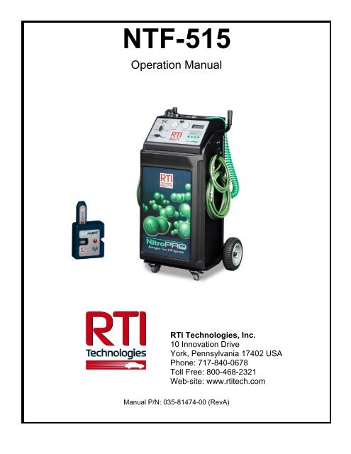
<strong>NTF</strong>-<strong>515</strong><br />
<strong>Operation</strong> <strong>Manual</strong><br />
<strong>RTI</strong> <strong>Technologies</strong>, Inc.<br />
10 Innovation Drive<br />
York, Pennsylvania 17402 USA<br />
Phone: 717-840-0678<br />
Toll Free: 8<strong>00</strong>-468-2321<br />
Web-site: www.rtitech.com<br />
<strong>Manual</strong> P/N: <strong>035</strong>-<strong>81474</strong>-<strong>00</strong> (RevA)
TABLE OF CONTENTS<br />
Pictograms 3<br />
Health, Safety and Environmental Aspects...................... 3<br />
Description of the <strong>NTF</strong>-<strong>515</strong> Membrane 4<br />
Process Parameters 5<br />
Unpack & Check Equipment 6<br />
Safety Precautions 6<br />
<strong>Operation</strong> 7<br />
Nitrogen Purity Selection 7<br />
Automatic Tire Filling 8<br />
<strong>Manual</strong> Single Tire Vacuum and Fill 10<br />
Testing Nitrogen Purity 11<br />
Maintenance 12<br />
Trouble Shooting Guide 13<br />
Parts Identification 14<br />
NORMAL OPERATION – LOSS OF PRESSURE<br />
Nitrogen is generated by the <strong>NTF</strong>-<strong>515</strong> and retained in the storage<br />
tank. Nitrogen generation stops when this tank fills to the specified<br />
design pressure.<br />
The pressure in the <strong>NTF</strong>-<strong>515</strong> storage tank may drop after extended<br />
non-use (over night for example). This is normal, and is similar to<br />
air compressors that will periodically cycle on to replenish pressure<br />
lost in the air storage tank and attached delivery system.<br />
Permeation through service hoses, fill nozzles, valves and other<br />
components directly associated with nitrogen generation is to be<br />
expected, and does not impact normal operation.<br />
It may take a few minutes to replenish the pressure in the storage<br />
tank to maximum next time the <strong>NTF</strong>-<strong>515</strong> is used. This is normal.<br />
2
PICTOGRAMS<br />
Warning: Hazard that can cause death or serious injury. Follow the instructions.<br />
Caution: Danger that can cause damage to the equipment. Follow the<br />
instructions.<br />
Warning: Risk of death due to suffocation.<br />
Risk of fire: Oxygen-enriched air leads to an increased risk of fire in the event of<br />
contact with flammable products.<br />
High pressure risk: Follow the instructions with respect to compressed gasses.<br />
Instructions with respect to the environment.<br />
HEALTH, SAFETY AND ENVIRONMENTAL ASPECTS<br />
GENERAL<br />
Correct use of the <strong>NTF</strong>-<strong>515</strong> Nitrogen generator is important for your personal safety and for trouble-free<br />
functioning. Incorrect use can cause damage to the <strong>NTF</strong>-<strong>515</strong> or can lead to incorrect gas supply to the<br />
customer’s process.<br />
Warning: Read this manual before you start operating the <strong>NTF</strong>-<strong>515</strong>. Prevent<br />
accidents and damage. Contact <strong>RTI</strong> if you detect a problem that you cannot<br />
solve with this manual.<br />
COMPRESSED AIR<br />
Warning: Ensure that the feed air pressure can not exceed 190 psig.<br />
3
NITROGEN AND OXYGEN<br />
The <strong>NTF</strong>-<strong>515</strong> generates Nitrogen as a product. Oxygen enriched air is released as waste.<br />
Warning<br />
Nitrogen can cause suffocation. Oxygen enriched air leads to increased risk of<br />
fire in the event of contact with flammable products. Make sure that there is<br />
adequate ventilation at all times!<br />
Do not install the <strong>NTF</strong>-<strong>515</strong> in an area where explosive substances may be<br />
present.<br />
DESCRIPTION OF THE <strong>NTF</strong>-<strong>515</strong> MEMBRANE<br />
GENERAL<br />
The <strong>NTF</strong>-<strong>515</strong> separates compressed air into nitrogen and an oxygen enriched air stream. The<br />
separation system is based on membrane technology. The compressed air comes from a central<br />
system or from a dedicated compressor.<br />
The nitrogen produced is stored in the nitrogen storage vessel. The <strong>NTF</strong>-<strong>515</strong> then switches on and off,<br />
depending on the nitrogen demand.<br />
Separation Principle<br />
Separation Layer<br />
Support Layer<br />
B<br />
Pressurized<br />
Air<br />
A<br />
Nitrogen<br />
C<br />
HO,H 2 2 O 2 N 2<br />
F<br />
S<br />
A Pressurized air inlet F Fast<br />
B Hollow fiber membrane S Slow<br />
C Nitrogen outlet<br />
Ambient air contains nitrogen (78.1%), oxygen (20.9%), argon (1%), carbon dioxide, water vapor and<br />
traces of other inert gasses. Pressurized air (A) is fed through the hollow fiber membrane (B). The<br />
various air components diffuse through the wall of the membrane.<br />
The diffusion rate differs for the various gases:<br />
Oxygen and water vapor have a high diffusion rate and permeate rapidly through the membrane<br />
wall.<br />
Nitrogen has a low diffusion rate and permeates slowly through the membrane wall.<br />
At the exit of the membrane (C), pressurized nitrogen is released.<br />
4
560-80374-<strong>00</strong><br />
PROCESS PARAMETERS<br />
The nitrogen production depends on these parameters:<br />
Flow rate<br />
Temperature<br />
Membrane<br />
pressure<br />
External<br />
pressure<br />
The lower the flow rate of compressed air through the hollow fiber membrane, the<br />
more oxygen can permeate through the membrane wall. As a result, the nitrogen<br />
produced at the outlet will have a higher purity. Nitrogen purity can be adjusted with<br />
the flow control valve.<br />
The <strong>NTF</strong>-<strong>515</strong> operates at a temperature between 40-110 0 F (70-80 0 F optimally). If<br />
the temperature increases, the pressurized air consumption will also increase. Do<br />
not place the system in a room where the temperature may rise unnecessarily high.<br />
Allow enough piping between the compressor exit and the <strong>NTF</strong>-<strong>515</strong> inlet so that the<br />
hot compressed gas has time to cool within the specifications listed in this manual.<br />
A higher membrane pressure will increase the capacity (i.e. nitrogen output) of the<br />
<strong>NTF</strong>-<strong>515</strong>. Pressure also enables operation of the pneumatic pressure switch.<br />
There must be atmospheric pressure at the outlet. The capacity and the purity of<br />
the nitrogen gas decreases strongly if the vent pressure exceeds the atmospheric<br />
pressure.<br />
CLEAN SHOP AIR – PROPER FLOW & PRESSURE<br />
Many shop air supplies have an oiler installed to provide lubrication for air tools. The life of the filters in<br />
the <strong>NTF</strong>-<strong>515</strong> will be increased if the shop air supply is free from moisture and oil.<br />
Recommendation - install a separate air line without an oiler to connect to the <strong>NTF</strong>-<strong>515</strong>. If this is not<br />
practical, consider installing a separate pre-filter before connecting the <strong>NTF</strong>-<strong>515</strong> to limit potential<br />
contamination to the <strong>NTF</strong>-<strong>515</strong> filters.<br />
Also, ensure the shop air supply meets the pressure and flow ratings stated in the <strong>NTF</strong>-<strong>515</strong> <strong>Operation</strong><br />
<strong>Manual</strong> for maximum nitrogen generation.<br />
Indicator<br />
CLEAN<br />
CHANGE<br />
... IMPORTANT ...<br />
The condition of the Filter Element (mounted on rear of unit) can<br />
only be checked when shop air is connected to the unit and it is in<br />
the FILL TIRE mode of operation with Nitrogen being generated<br />
and filling the tank. It may be necessary to press the trigger on the<br />
fill wand to cause the tank filling. At all other times the Indicator will<br />
not be visible.<br />
The Filter Element must be changed when the indicator moves into<br />
the CHANGE area and at least annually to protect the membrane<br />
warranty.<br />
5
UNPACK & CHECK EQUIPMENT<br />
Ensure that all components were delivered.<br />
Ensure that the compressed air source meets specification:<br />
Oil content of the compressed air is below 0.01mg/m 3 .<br />
Ensure that the compressed air pressure and quality is always as prescribed.<br />
Ensure that the air capacity is sufficient.<br />
CHARGE BATTERY FOR AT LEAST 5 HOURS PRIOR TO FIRST USE.<br />
SAFETY PRECAUTIONS<br />
Warning<br />
Ensure there is sufficient ventilation.<br />
Only feed the <strong>NTF</strong>-<strong>515</strong> with air.<br />
Keep the air feed to the <strong>NTF</strong>-<strong>515</strong> clean and free of vapors of organic solvents and<br />
other contaminants. Do not place the <strong>NTF</strong>-<strong>515</strong> in a room where organic solvent<br />
vapors may be present.<br />
Keep the ambient temperature between 40 and 110 °F. Do not connect hot<br />
compressed air directly from a compressor to the inlet of the <strong>NTF</strong>-<strong>515</strong>.<br />
Regular maintenance should be performed on the <strong>NTF</strong>-<strong>515</strong> to ensure proper and<br />
safe operation. Ensure that instructions concerning health and safety are compliant<br />
with local regulations.<br />
ENVIRONMENTAL ASPECTS<br />
The use and maintenance of the <strong>NTF</strong>-<strong>515</strong> do not include environmental dangers.<br />
Most parts are made of metal and can be disposed of in a manner consistent with<br />
local regulations.<br />
Make sure that instructions concerning health, safety and environment are<br />
compliant with all local regulations.<br />
6
OPERATION<br />
FOREIGN SUBSTANCES IN TIRES<br />
Tires which have been in service may contain foreign substances such as leak sealers. It is important<br />
that these substances are not pulled into the NitroPro unit during the vacuum procedure, resulting in<br />
possible performance issues and costly repairs not covered by <strong>RTI</strong>’s warranty.<br />
When servicing a vehicle, first check the valve stems and valve stem caps for any type of fluid or<br />
foreign substance. Install deflators and allow all four tires to deflate to zero pressure. Then check the<br />
deflators for any indication of fluids or foreign substances.<br />
Do not use the NitroPro vacuum procedure on any tire where evidence of fluids or foreign substances<br />
are detected on the valve stems, valve stem caps or deflators. Instead, follow a four step “deflateinflate-deflate-inflate”<br />
process to achieve desired nitrogen purity.<br />
NITROGEN PURITY SELECTION<br />
<strong>NTF</strong>-<strong>515</strong> allows an operator to select desirable purity of generated Nitrogen.<br />
Purity selector is located in the left lower corner of the unit’s rear panel.<br />
Turn selector knob to desirable purity before starting nitrogen generation. If<br />
storage tank is filled with 95% pure Nitrogen, it must be fully emptied before<br />
switching to 98% purity. To empty the tank, attach tire deflator to Nitrogen<br />
Purity Test Port located on the front panel and release stored Nitrogen to<br />
atmosphere.<br />
Higher purity Nitrogen generation and vehicle service times will double if<br />
98% pure Nitrogen is selected.<br />
After purity is selected, <strong>NTF</strong>-<strong>515</strong> can be used either in automatic or manual<br />
mode.<br />
7
AUTOMATIC TIRE FILLING<br />
PURGE/FILL AND TOP OFF CYCLES<br />
1. Attach air supply (150 PSI max) to the unit. Verify pressure indicated on panel mounted Air<br />
Pressure gauge is between 120 - 150 PSI.<br />
2. Turn both valve knobs to FILL TIRE.<br />
3. Allow unit to build pressure in Nitrogen storage tank as shown on N 2 pressure gauge (120 PSI).<br />
4. Turn on POWER switch on the top of control panel. PCB will display battery charge status (HI<br />
or LO). Ensure that 12VDC battery is charged. See section on Battery charging for more<br />
information.<br />
5. Connect hoses to tires. <strong>NTF</strong>-<strong>515</strong> unit is equipped with four service hoses, coiled on both sides.<br />
12 FT long hoses should be connected to tires, nearest to the operator. 24 FT long hoses<br />
should be connected to farthest tires on the vehicle. Ensure that air chucks are fully engaged<br />
with valve stems for proper service.<br />
6. Set the final target pressure by pressing + or – buttons.<br />
7. To change Over Pressure and Nitrogen Purge Cycles settings see following sections.<br />
8. Press and hold START button for two seconds (until long beep). This will start Purge/Fill cycle.<br />
For Top Off cycle press START button momentarily and release it. Top Off cycle will start<br />
immediately.<br />
One complete Purge/Fill cycle will deflate all tires to 10% of target pressure<br />
(approximately 3 PSI for 30 PSI target), inflate to target pressure, deflate to 50% of target<br />
pressure then inflate to final target pressure. (If two or more Purge Cycles are programmed the<br />
above process will be repeated).<br />
9. Unit will beep at the end of service and word END will appear on LCD.<br />
10. It’s recommended to wait 10-15 seconds after the end of service before disconnecting hoses.<br />
11. Press any key to stop process.<br />
8
TOP OFF AND PURGE/FILL CYCLE COUNTER<br />
<strong>NTF</strong>-<strong>515</strong> will total the number of Top Offs and Purge/Fill cycles performed.<br />
1. Press and hold + and - buttons simultaneously until unit beeps.<br />
2. Press + or – button.<br />
3. First displayed number shows thousands of Top Offs.<br />
4. Press + or - button. Hundreds, tens and ones of Top Offs will be displayed.<br />
5. Press + or - button. Thousands of Purge/Fill cycles will be displayed.<br />
6. Press + or - button. Hundreds, tens and ones of Purge/Fill cycles will be displayed.<br />
7. Press + or - button to exit counter mode.<br />
OVERPRESSURE SETTING (OPS) AND PURGE/FILL CYCLES<br />
1. Turn POWER switch on.<br />
2. Press N2 button once.<br />
3. Press + or – buttons to change the Overpressure Setting.<br />
4. Press START button to save the Overpressure Setting.<br />
5. Press N2 button.<br />
6. Press + or – buttons to select desirable number of Purge/Fill cycles.<br />
7. Press START button to save the number of Purge/Fill cycles.<br />
BATTERY CHARGING<br />
<strong>NTF</strong>-<strong>515</strong> is powered by an internal 12VDC battery. Charge battery for at<br />
least 5 hours prior to first use. Battery charge level is displayed immediately<br />
upon unit powering. HI indicates that battery is charged. LO indicates low<br />
charge and battery needs to be recharged. Plug battery charger in 110VAC<br />
wall outlet and insert plug into battery charging port. Unit can be operated<br />
during recharging process. Typical recharge time is 3-5 hour depending on<br />
battery condition.<br />
9
MANUAL SINGLE TIRE VACUUM AND FILL<br />
VACUUM TIRE<br />
1. Install deflators and check for foreign substances as explained earlier.<br />
2. Connect shop air to the air inlet port on the rear of the <strong>NTF</strong>-<strong>515</strong>. Verify pressure indicated on panel<br />
mounted Air Pressure gauge is between 120 - 150 PSI.<br />
3. Turn both panel valves to VACUUM TIRE.<br />
4. Remove deflator and connect Digital Pressure Gauge (on the end of the <strong>NTF</strong>-<strong>515</strong> coiled green<br />
hose) to the tire valve stem. Squeeze handle to vacuum the tire. Periodically release the handle to<br />
observe the vacuum level. Do not vacuum to a level where the tire starts to deform.<br />
If your application requires an inlet pressure of 1<strong>00</strong> - 119 PSI, an adjustment to the<br />
automatic pressure switch may be required.<br />
Contact <strong>RTI</strong> Technical Support at 8<strong>00</strong>-468-2321 for further details.<br />
FILL TIRE<br />
1. Connect shop air to the air inlet port on the rear of the <strong>NTF</strong>-<strong>515</strong>. Verify pressure indicated on panel<br />
mounted Air Pressure gauge is between 120 - 150 PSI. Verify Nitrogen pressure indicated on the<br />
panel mounted N 2 Pressure gauge is adequate for service.<br />
2. Turn both panel valves to FILL TIRE.<br />
3. Connect Pressure Gauge (on the end of the <strong>NTF</strong>-<strong>515</strong> coiled green hose) to the tire valve stem.<br />
Squeeze handle to fill tire. Periodically release the handle to observe the pressure level. Stop when<br />
the pressure reaches the tire manufacturer’s recommended inflation pressure. Do not over inflate.<br />
4. Install an <strong>RTI</strong> N 2 Cap (Package of 2<strong>00</strong> - Part Number 355-8<strong>00</strong>26-<strong>00</strong>).<br />
Note: While not using the <strong>NTF</strong>-<strong>515</strong> to fill or vacuum tires, generate Nitrogen and<br />
increase the Nitrogen pressure in the internal storage tank by turning both panel<br />
valves to STANDBY.<br />
Note: While using the <strong>NTF</strong>-<strong>515</strong>, the automatic drain feature of the filters may<br />
activate to remove excess water and oil. This is normal with the standard operation<br />
of the unit.<br />
10
TESTING NITROGEN PURITY<br />
The <strong>NTF</strong>-<strong>515</strong> Purity Tester can be used to determine the percent of nitrogen produced by the <strong>NTF</strong>-<strong>515</strong><br />
by connecting to the Test Port. It can also be used to determine the percent of nitrogen in the air in the<br />
tires after performing a service.<br />
Refer to the <strong>Operation</strong> <strong>Manual</strong> for the <strong>NTF</strong>-<strong>515</strong> Purity Tester (<strong>035</strong>-81169-<strong>00</strong>) for further details.<br />
HELPFUL HINT – PURITY TESTING<br />
When using the Purity Tester to measure nitrogen purity in a tire, you can minimize the<br />
pressure loss, and corresponding refill requirements, by removing the Tester from the<br />
valve stem after a sample has been obtained.<br />
You will notice that the reading continues to climb after the Tester has been removed;<br />
this a function of the response time of the internal sensor. Once the rate of change in the<br />
reading begins to slow down or stabilize, reapply the Tester to the valve stem to obtain<br />
another sample.<br />
This method is particularly effective at the beginning of the test procedure, when large<br />
changes in nitrogen purity readings quickly occur.<br />
Even if you follow this method, you should ALWAYS RECHECK THE TIRE PRESSURE<br />
when purity testing is complete and replenish nitrogen as necessary.<br />
11
560-80374-<strong>00</strong><br />
MAINTENANCE<br />
Indicator<br />
Part Action Frequency<br />
Filter Element<br />
Replace Yearly or when indicator on the filter<br />
head moves to the CHANGE area as<br />
shown in the illustration to the right.<br />
Automatic Drain Clean When required<br />
CLEAN<br />
CHANGE<br />
... IMPORTANT ...<br />
The condition of the Filter Element (mounted on rear of unit) can only be checked when shop air is<br />
connected to the unit and it is in the FILL TIRE mode of operation with Nitrogen being generated<br />
and filling the tank. It may be necessary to press the trigger on the fill wand to cause the tank<br />
filling. At all other times the Indicator will not be visible.<br />
The Filter Element must be changed when the indicator moves into the CHANGE area and at least<br />
annually to protect the membrane warranty.<br />
REPLACE FILTER ELEMENT<br />
Disconnect the air supply.<br />
Let the system depressurize until the air pressure gauge reads 0 PSI.<br />
Unscrew the bleed screw (F) slowly to ensure that the filter is<br />
depressurized.<br />
Turn the filter bowl (E) counter- clockwise and pull the bowl from the<br />
filter housing (A).<br />
Unscrew the blue knob (D).<br />
Remove the old filter element (C).<br />
Clean the sieve (B) and the filter house, if necessary.<br />
Install a new filter element (C).<br />
Assemble the parts in the reverse order.<br />
Note: A periodic check of the automatic drains is necessary to ensure maximum membrane life. To<br />
verify float is functioning correctly, open the filter bowl by turning one quarter turn counterclockwise.<br />
Inspect for water or oil, an inactive float will be submerged, an active float will not. If<br />
float is found to be inactive follow clean automatic drain procedure or if necessary replace with<br />
part number 026-80386-<strong>00</strong>.<br />
12
CLEAN AUTOMATIC DRAIN<br />
Open the filter by turning the bowl one quarter turn counterclockwise.<br />
Unscrew the nut (F).<br />
Remove the drain unit (B-E) from the filter bowl (A).<br />
Remove the O-ring (E).<br />
Carefully pull the floating house (B) from the seat (D). Do not bend<br />
the needle (C).<br />
Clean the parts with soap and water. Make sure that the needle<br />
bore is open and clean.<br />
Assemble the parts in the opposite direction. Make sure that the<br />
parts are dry before reassembly.<br />
AUTOMATIC PRESSURE SWITCH SETTING<br />
The automatic pressure switch is factory pre-set to shut off shop air consumption at 120 PSI. This<br />
switch will then automatically reset when the N 2 Pressure inside the tank drops by approximately 25<br />
PSI.<br />
If your application requires an inlet pressure of 1<strong>00</strong> - 119 PSI, an adjustment to the automatic pressure<br />
switch is possible. Please contact <strong>RTI</strong> Technical Support at 8<strong>00</strong>-468-2321 x 1 for further details.<br />
TROUBLE SHOOTING GUIDE AND POSSIBLE ERROR MESSAGES<br />
Problem Possible Cause Solution<br />
1. Display does not light Dead Battery Recharge battery<br />
2. Inflation process starts, but<br />
does not complete<br />
3. Hose connectors will not seal<br />
to the tire stems<br />
4. Hose connectors leak while<br />
not connected to tires<br />
5. E4 on display<br />
6. E5/E16 on display<br />
Low supply pressure or leaks<br />
exist<br />
Hose connections worn<br />
Hose connections worn<br />
Over inflation due to blocked<br />
hose<br />
Unit powered ON while<br />
connected to tires<br />
Check supply pressure & confirm<br />
leaks do not exist<br />
Replace connectors<br />
Replace connectors<br />
Remove blockage or replace hose<br />
Remove hoses from tires and turn<br />
power OFF/ON again<br />
7. E6/E8/E9 on display PCB or sensor error Contact <strong>RTI</strong> <strong>Technologies</strong><br />
8. E10 on display Low battery charge Charge battery at least for 5 hours<br />
9. E11/E12 on display PCB fault Contact <strong>RTI</strong> <strong>Technologies</strong><br />
13
PARTS IDENTIFICATION<br />
Part Number<br />
Description<br />
1 026-80379-<strong>00</strong> 2 inch Gauge 0-160 psig/bar 1/4MPT<br />
2 023-80364-<strong>00</strong> FTG Test Port 1/4 MPT X valve stem<br />
16<br />
25<br />
11 13<br />
3 022-8<strong>00</strong>28-<strong>00</strong> 3-way ball valve 1/4 FPT (BHD)<br />
4 026-80330-<strong>00</strong> pneumatic vacuum pump<br />
5 022-80149-<strong>00</strong> pneumatic pilot valve<br />
6 022-80131-<strong>00</strong> adjustable pneumatic pressure switch<br />
12<br />
3<br />
26<br />
15<br />
14<br />
7 022-80128-<strong>00</strong> check valve 3/8 FPT<br />
8 022-80377-<strong>00</strong> 15 gal vertical tank<br />
9 026-80395-<strong>00</strong> nitrogen membrane (5.1 CFM)<br />
10 022-80151-<strong>00</strong> needle valve 3/8 FPT<br />
11 026-80396-<strong>00</strong> water filter with auto drain<br />
12 026-80386-<strong>00</strong> auto drain float<br />
13 026-80397-<strong>00</strong> oil filter with auto drain<br />
5<br />
18<br />
24<br />
23<br />
9<br />
6<br />
7<br />
8<br />
10<br />
17<br />
14 026-80398-<strong>00</strong> moisture filter<br />
15 026-80399-<strong>00</strong> carbon bed<br />
16 028-80362-<strong>00</strong> coiled green hose<br />
17 023-80395-<strong>00</strong> air chuck with digital pressure gauge<br />
18 040-80213-<strong>00</strong> 12 VDC battery<br />
19 026-80513-<strong>00</strong> battery charger<br />
20 024-80139-<strong>00</strong> circuit board with sensor<br />
21 025-80414-<strong>00</strong> solenoid manifold<br />
22 025-80415-<strong>00</strong> diverter valve<br />
23 023-80390-<strong>00</strong> air chuck<br />
24 021-80169-01 hose clamp<br />
25 060-81638-12 12 foot hose<br />
26 060-81638-24 24 foot hose<br />
27 024-8<strong>00</strong>66-<strong>00</strong> power switch<br />
22 21 3 2 1 27 1 20<br />
19<br />
4 (under panel)<br />
14