instalation instructions 1500 - IMI Cornelius
instalation instructions 1500 - IMI Cornelius
instalation instructions 1500 - IMI Cornelius

Create successful ePaper yourself
Turn your PDF publications into a flip-book with our unique Google optimized e-Paper software.
INSTALLATION INSTRUCTIONS<br />
WATER COOLED BEER REMOTE COOLERS<br />
INTRODUCTION<br />
<strong>IMI</strong> <strong>Cornelius</strong> has a highly versatile range of Classic Remote Coolers. The Classic <strong>1500</strong> is the latest<br />
beer remote cooler development and is aimed at large, managaed accounts where quality brand<br />
promotion is paramount.<br />
The Classic <strong>1500</strong> Water Cooled Remote Cooler has a fully sealed refrigeration system in the base unit<br />
with heat dissipated via a water/glycol mixture to an exterior wall mounted Discharge Unit. The<br />
coolant is pumped via a recirculation pump which is mounted in the base unit. The Classic <strong>1500</strong> can be<br />
sited in a chilled cellar with minimal heat output.<br />
This derivation of the Classic remote cooler incorporates the latest refrigeration technology, including<br />
R404a refrigerant and Double Wash Evaporator to increase reliability and efficiency.<br />
The Product Cooler lid format consists of a 3 stage top mounted water recirculation pump giving a<br />
nominal 18m lift. There are ten coils each 5mteres in length, retained in two replaceable fabricated<br />
carriers mounted each side of the pump. The product cooler ice bank is of a nominal 30kg. It is<br />
controlled via an electronic ice bank controller and three-pin probe.<br />
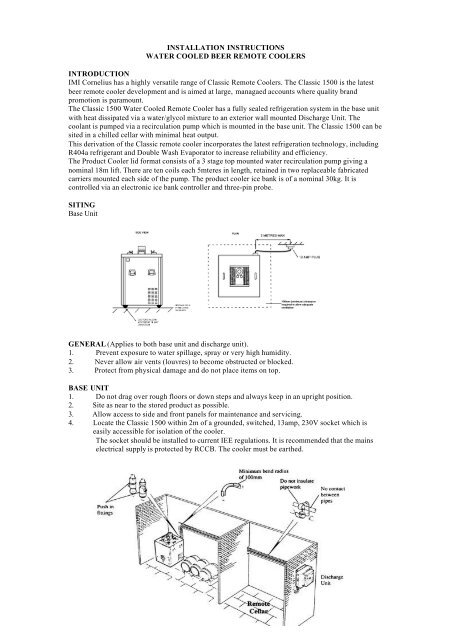
SITING<br />
Base Unit<br />
GENERAL (Applies to both base unit and discharge unit).<br />
1. Prevent exposure to water spillage, spray or very high humidity.<br />
2. Never allow air vents (louvres) to become obstructed or blocked.<br />
3. Protect from physical damage and do not place items on top.<br />
BASE UNIT<br />
1. Do not drag over rough floors or down steps and always keep in an upright position.<br />
2. Site as near to the stored product as possible.<br />
3. Allow access to side and front panels for maintenance and servicing.<br />
4. Locate the Classic <strong>1500</strong> within 2m of a grounded, switched, 13amp, 230V socket which is<br />
easily accessible for isolation of the cooler.<br />
The socket should be installed to current IEE regulations. It is recommended that the mains<br />
electrical supply is protected by RCCB. The cooler must be earthed.
NB. If the cooler cuts out in normal operation then there will be a three minute delay before the unit<br />
continues it’s operation.<br />
DISCHARGE UNIT<br />
1. The Discharge Unit should be mounted in a convenient position on an EXTERIOR wall and<br />
provide access for pipes and electrical cables to the Base Unit (maximum 30m run length with<br />
a maximum lift of 16m included in the 30m). If no exterior wall is available within 30 metres<br />
of the Base Unit, then mount inside on a wall in a cool room with plenty of fresh air<br />
ventilation. Avoid warm areas (i.e. cupboards or small storerooms).<br />
2. The Discharge Unit is designed to operate in the range of ambient temperatures<br />
–10 o C to 35 o C.<br />
INSTALLATION<br />
GENERAL<br />
1 Installation must be carried out by a suitably trained person and comply with national and<br />
local codes for connection to the electrical supply.<br />
BASE UNIT<br />
1. Remove the packaging site unit in operating position and fill the water bath with cold mains<br />
water, to the level of the overflow. The cooler should not be moved once the water bath has<br />
been filled with water.<br />
2. Assemble Ball Valves to pump. Ensure these are closed. Check pump is plugged in.<br />
DISCHARGE UNIT<br />
Secure the Discharge Unit t the wall in a manner capable of supporting the Discharge Unit weight<br />
(9kg). Two suitable fixing screws and rawl plugs should be used which secure the Discharge Unit via<br />
two holes located at the top of the unit.<br />
GLYCOL LINES/WIRING<br />
1. Using 0.75mm 2 electrical cable (not supplied) & plug (supplied), connect the Discharge Unit<br />
to the Base Unit. The plug socket is located to the rear of the cooler. Note: This is a nominal<br />
24volt supply. For runs over 50m use thicker cable, 2.5mm 2 , to ensure the Discharge Unit<br />
functions correctly.<br />
2. Complete the glycol circuit by connecting the pipework between the Base Unit and the<br />
Discharge Unit with the aid of the fittings provided. Avoid ups and downs in each glycol line<br />
as this may create air locks. Do not kink or crush the tubing (minimum bend radius of 100mm)<br />
and support where necessary.<br />
This circuit will carry hot glycol solution under pressure and it is important for safety reasons<br />
that suitable tubing is used. Consult a specialist tubing manufacturer or contact <strong>Cornelius</strong> in<br />
case of difficulty. PVC tubing, whether braided or not, is not suitable for this application.<br />
The tubing ID must be sufficient to ensure a minimum flowrate of 6 litres/minute in the glycol<br />
circuit. For a pipe run of 30m out and 30m back, and id of at least 11.5mm will be required.<br />
SYSTEM COMMISSIONING<br />
1. It is essential the following procedure is strictly adhered to, to ensure the glycol<br />
circuit primed correctly.<br />
2. Mix monopropylene glycol and water to give a solution of 30% Glycol 70% Water.<br />
Do not use ethylene glycol. Ensure that sufficient water/glycol mixture is available for pouring<br />
into the reservoir tank before switching the system on. You will need:-
4litres for the tank,<br />
4litres for every 35 metres of 12mm ID glycol line.<br />
3. Disconnect one of the glycol lines from the rear of the base unit and fill the glycol tank.<br />
Reconnect the glycol line.<br />
4. Connect the 3 pin moulded plug to the mains and switch on the power to the Base Unit.<br />
5. The base mounted coolant pump will start to prime the system.<br />
As the coolant level drops, keep filling the reservoir with the mixture, ensuring it does<br />
not drop below the minimum level. DO NOT ALLOW THE BASE MOUNTED<br />
COOLANT RECIRCULATION PUMP TO RUN DRY.<br />
COMPLETING THE INSTALLATION<br />
1. The cooler is factory set to make an icebank.<br />
2. Connect the product coils to product lines. Check for leaks.<br />
3. Connect the recirculation lines to the ball valves. Open both valves and top up the water level<br />
where necessary. Check the water flow<br />
4. Allow the cooler to build up its icebank (5 hours minimum).<br />
NOTE: There is a low temperature thermostat which will not allow the fan on the Discharge Cooler to<br />
operate if the temperature of the coolant is low. On installation, therefore, the fan may not start for<br />
some time.<br />
MAINTENANCE INSTRUCTIONS<br />
1 Check that the water level in the water bath is up to the overflow.<br />
2 Inspect the condition of the icebank.<br />
3 Check the Discharge Unit fan is working and that there are no obstructions or blockages of the<br />
air flow vents.<br />
N.B. The fan is controlled by a thermostat mounted within the Base Unit. It may switch the fan<br />
off when the air into the discharge unit drops below approximately 12 o C.<br />
4 Check and clean the heat exchanger fins on the Discharge Unit. Dirt and dust can block the air<br />
vents in the heat exchanger, severely reducing the effectiveness of the refrigeration system.<br />
5 Check the condition and effectiveness of the Python insulation.<br />
6 Check the Python for correct water recirculation.<br />
7 At regular intervals, to be determined by the owner and/or user, the cooler should be checked<br />
for electrical safety.<br />
8 Check the glycol lines are not kinked or crushed. Check for leaks.<br />
9 Check the level of coolant (Water/Glycol) in the reservoir and re-fill as necessary with a 30%<br />
Glycol; 70% Water mixture.


![Evo 100[1].pdf - IMI Cornelius](https://img.yumpu.com/49943940/1/190x255/evo-1001pdf-imi-cornelius.jpg?quality=85)