

Sleeved Plug Valves - Camacvc.com
Sleeved Plug Valves - Camacvc.com
Sleeved Plug Valves - Camacvc.com

You also want an ePaper? Increase the reach of your titles
YUMPU automatically turns print PDFs into web optimized ePapers that Google loves.
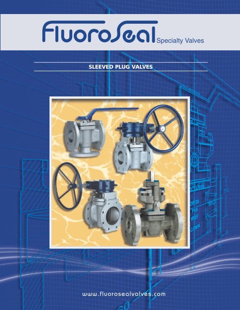
SLEEVED PLUG VALVES<br />
www.fluorosealvalves.<strong>com</strong>
PLUG VALVES<br />
9<br />
4<br />
2<br />
3<br />
10<br />
5<br />
1<br />
6<br />
8<br />
7<br />
Design Features Summary<br />
1. Bi-directional inline bubble tight seal independent of line pressure.<br />
2. Multiple external bubble tight seals independent of line pressure.<br />
3. Direct mechanical three point adjustment independent of line pressure.<br />
4. Independent travel stops.<br />
5. Full encapsulation and retention of all leading edges of PTFE sleeve and<br />
top seal <strong>com</strong>ponents.<br />
6. Full lip at port openings protects PTFE sleeve.<br />
7. Contoured waterway assures minimum flow turbulence characteristic.<br />
8. No body cavities to entrap flow media.<br />
9. Positive flow direction indication.<br />
10. Drilled and tapped flange mounting pads independent of cover and top<br />
seal assembly.<br />
Other Features<br />
- Bi-directional flow.<br />
- Quarter turn operation<br />
- Nonlubricated<br />
- Self-cleaning on each operation.<br />
- Two way and multiport configurations<br />
- Special service and jacketed designs available.<br />
- All casting <strong>com</strong>ponents traceable to mill test certificates.<br />
- Investment cast on all materials for sizes 1/2" - 10" (Class 150)<br />
- Investment cast on all materials for sizes 1/2" – 6" (Class 300)<br />
- Investment cast on all materials for sizes 1/2" – 6" (Class 600)<br />
- Castings meet level 1 casting specifications<br />
- Heavy duty gears are standard on all our valves
DESIGN FEATURES<br />
Design Features<br />
FluoroSeal®, Nonlubricated, <strong>Sleeved</strong> <strong>Plug</strong> <strong>Valves</strong> possess the state-of-the-art in PTFE fluorocarbon seated<br />
designs. With little or no maintenance and trouble free operation, a high integrity bubble tight seal is provided<br />
both inline and to atmosphere. The specific design features contributing to the superiority of this product<br />
are described, as a function of their individual purpose and engineering precautions taken to assure maximum<br />
service life.<br />
PTFE fluorocarbon, utilized in the FluoroSeal sleeve and top seal <strong>com</strong>ponents, is universally corrosion resistant<br />
being inert to all but a few rarely encountered chemicals. It is thermoplastic that can be used at a continuous<br />
service temperature of 400°F (204°C) and much higher temperatures can be satisfactorily sustained for shorter<br />
periods. Having a very low coefficient of friction it is self-lubricating negating the need for any other lubrication.<br />
Since PTFE is susceptible to deformation as it is put under load and to cold flow, as it be<strong>com</strong>es more pliable<br />
at elevated temperatures, precaution must be taken to control this activity to the advantage of the intended<br />
purpose of the valve.<br />
The FluoroSeal internal body configuration has been designed to totally contain all of the leading edges of the<br />
PTFE sleeve at the top, at the bottom and around the entire port opening adjacent to the waterway. Any tendency<br />
the sleeve has to grow is ac<strong>com</strong>modated by relief areas, designed for this purpose, positioned at 90<br />
degrees to the body port openings, The port defining metal lips protects the PTFE sleeve from erosion and any<br />
possibility of sleeve rotation within the body.<br />
The waterway in the body has been designed with a contour providing a flow path that assures a minimum flow<br />
turbulence characteristic. The critical sealing areas circumferentially around the top and bottom of the sleeve<br />
and around the body port openings are maintained by means of an adjustable tapered plug <strong>com</strong>pressing the<br />
PTFE sleeve over raised ribs.<br />
The PTFE top seal <strong>com</strong>ponents are similarly contained and protected from damage. A counter bore is provided<br />
at the top of the metal body to encapsulate the outside diameter of the formed PTFE diaphragm in conjunction<br />
with the formed metal diaphragm and to protect it from rupturing by regulating the amount of <strong>com</strong>pression at<br />
this point. The inside diameter of the formed PTFE diaphragm, adjacent to the plug stem, is also contained by<br />
means of a unique lip design of the formed metal diaphragm preventing extrusion and maintaining the stem<br />
seal throughout variable service conditions. This unique formed metal diaphragm also provides a positive electrical<br />
ground between the plug and body eliminating the need for an extra <strong>com</strong>ponent to fulfill this function<br />
as in the case of other valve manufacturers’ designs.<br />
Three point external adjusting bolts in the cover assures equilibrium to the <strong>com</strong>pression of the stem and inline<br />
seals by imparting a balanced force through a metal thrust washer located under the cover above the formed<br />
metal diaphragm. This mechanism provides a multiple seal to atmosphere and a double (downstream &<br />
upstream) bi-directional inline seal.<br />
Independent wrench stops are cast on the cover to limit the stroke at the open and close positions without<br />
endangering the integrity of the seal adjustment as in other manufacturers’ designs. Parallel flats are machined<br />
on the sides of the plug stem providing positive indication of the direction of flow at all time, independent of<br />
other position indicators.<br />
All major pressure containing <strong>com</strong>ponents, body, plug and cover, of FluoroSeal valves, are fully traceable to mill<br />
test certificates assuring material authenticity. Quality levels are maintained through continual inspection and<br />
manufacturing surveillance of these and all other <strong>com</strong>ponents. A concerted effort is made to conform to all regulatory<br />
authority requirements as where and when invoked, in keeping with FluoroSeal’s pledge of quality first.<br />
www.fluorosealvalves.<strong>com</strong><br />
1
VALVE COMPONENTS<br />
WRENCH<br />
ADJUSTING<br />
BOLT<br />
COVER<br />
COVER BOLTS<br />
COMBINATION<br />
FORMED METAL<br />
DIAPHRAGM AND<br />
STATIC ELIMINATOR<br />
THRUST WASHER<br />
PTFE DELTA RING<br />
COMBINATION<br />
PTFE DIAPRRAGN AND<br />
STEM SEAL COLLAR<br />
MATERIALS OF CONSTRUCTION<br />
Body and <strong>Plug</strong> 1<br />
Cover 2<br />
Cover Bolts 2<br />
Adjusting Bolts<br />
Thrust Washer<br />
Metal Diaphragm 3<br />
Delta Ring<br />
Diaphragm<br />
Sleeve 4<br />
Wrench Operator 5<br />
Wrench Bolt 5<br />
Gear Assembly<br />
Gear Adaptor 5<br />
Gear Mounting Bracket<br />
Mounting Bracket Bolts 5<br />
As specified<br />
Carbon Steel, 304 SS<br />
Steel, 304 SS<br />
304 SS<br />
304 SS<br />
304 SS, Monel<br />
PTFE Fluorocarbon<br />
PTFE Fluorocarbon<br />
PTFE Fluorocarbon<br />
Carbon Steel<br />
Steel<br />
Cast Steel Housing<br />
Steel<br />
304 SS<br />
Steel<br />
1. See "Technical Data" for material selections.<br />
2. Cover and bolt materials of standard valves will be supplied in accordance with<br />
the following table:<br />
PLUG<br />
PTFE SLEEVE<br />
SPECIFIED BODY MATERIAL COVER MATERIAL COVER BOLT MATERIAL<br />
Ductile Iron Carbon Steel ASTM A-193 GR. B7<br />
Carbon Steel Carbon Steel ASTM A-193 GR. B7<br />
All other materials CF 8 ASTM A-193 GR. B8<br />
3. Monel metal diaphragms will be supplied with valves having a monel or nickel<br />
body or plug. All others will be supplied with 304 SS diaphragms.<br />
4. Glass reinforced PTFE, PFA Fluorocarbon and UHMWPE sleeves are available on<br />
special order.<br />
5. 304 SS Available on special order.<br />
BODY<br />
2
2-WAY VALVES - DIMENSIONAL DATA<br />
Fig. R152F<br />
DIMENSIONS TO ANSI B16.5 & B.16.10<br />
SIZE L H D K G B F D Q N WT’S<br />
in. mm. in. mm. in. mm. in. mm. in. mm. in. mm. in. mm. in. mm. in. mm. NO. (kg.) (lbs.)<br />
1/2” 4.25 108.0 3.38 86 3.50 88.9 2.38 60.5 1.38 35.0 0.37 9.5 0.06 1.6 0.63 16.0 8.00 203 4 2.3 5<br />
3/4” 4.63 117.5 3.38 86 3.88 98.5 2.75 69.9 1.68 42.9 0.37 9.5 0.06 1.6 0.63 16.0 8.00 203 4 2.7 6<br />
1” 5.00 127.0 4.50 114 4.25 108.0 3.13 79.5 2.00 50.8 0.44 11.2 0.06 1.6 0.63 16.0 9.00 229 4 3.6 8<br />
1-1/2” 6.50 165.1 5.31 135 5.00 127.0 3.88 98.6 2.88 73.2 0.56 14.2 0.06 1.6 0.63 16.0 14.25 362 4 6.4 14<br />
2” 7.00 177.8 6.25 159 6.00 152.4 4.75 120.7 3.63 92.0 0.63 16.0 0.06 1.6 0.75 19.0 16.50 419 4 10.5 23<br />
*2-1/2” 8.00 203.2 6.56 167 7.50 190.5 5.50 139.7 4.13 104.6 0.75 19.0 0.06 1.6 0.75 19.0 16.50 419 4 16.4 36<br />
3” 8.00 203.2 6.56 167 7.50 190.5 6.00 152.4 5.00 127.0 0.75 19.0 0.06 1.6 0.75 19.0 16.50 419 4 16.4 36<br />
4” 9.00 228.6 7.63 194 9.00 228.6 7.50 190.5 6.19 157.2 0.94 23.9 0.06 1.6 0.75 19.0 23.63 600 8 26.8 59<br />
4” EG 9.00 228.6 9.10 231 9.00 228.6 7.50 190.5 6.19 157.2 0.94 23.9 0.06 1.6 0.75 19.0 7.25 184 8 35.9 79<br />
6” 10.50 266.7 10.80 274 11.00 279.4 9.50 241.3 8.50 215.9 1.00 25.4 0.06 1.6 0.88 22.4 7.25 184 8 55.5 122<br />
8” 11.50 292.1 12.75 324 13.50 342.9 11.75 298.5 10.63 269.8 1.13 28.7 0.06 1.6 0.88 22.4 9.75 248 8 1 100.0 220<br />
10” 13.00 330.2 14.68 373 16.00 406.4 14.25 362.0 12.75 323.9 1.19 30.2 0.06 1.6 1.00 25.4 9.75 248 12 2 150.0 330<br />
12” 14.00 355.6 16.40 417 19.00 482.6 17.00 431.8 15.00 381.0 1.25 31.8 0.06 1.6 1.00 25.4 10.00 254 12 2 198.6 437<br />
14” 15.00 381.0 17.40 442 21.00 533.4 18.75 476.3 16.25 412.8 1.38 35.1 0.06 1.6 1.12 28.4 10.00 254 12 3 295.0 650<br />
Dimensions for sizes larger than 14” available on request<br />
*21/2” valves are made from 3” casting, but flanges are machined to 21/2” dimensions<br />
N= Number of holes<br />
(1) 2 top holes in flanges are tapped for 3/4” - 10 UNC Threads<br />
(2) 2 top holes in flanges are tapped for 7/8” - 9 UNC Threads<br />
(3) 2 top holes in flanges are tapped for 1" -8 UNC Threads<br />
CLASS 150 LBS<br />
Flanged Ends<br />
Wrench Operated<br />
(EG) Enclosed Gear Operated<br />
Actuators optional on all sizes<br />
Fig. R302F<br />
DIMENSIONS TO ANSI B16.5 & B.16.10<br />
CLASS 300 LBS<br />
Flanged Ends<br />
Wrench Operated<br />
(EG) Enclosed Gear Operated<br />
Actuators optional on all sizes<br />
SIZE L H D K G B F D Q N WT'S<br />
in. mm. in. mm. in. mm. in. mm. in. mm. in. mm. in. mm. in. mm. in. mm. NO. (kg) (lbs.)<br />
1/2" 5.5 139.7 3.38 86 3.75 95.3 2.63 66.8 1.38 35 0.56 14.2 0.06 1.6 0.63 16 8 203 4 3.2 7<br />
3/4" 6 152.4 3.38 86 4.63 117.6 3.25 82.6 1.69 42.7 0.63 16 0.06 1.6 0.75 19 8 203 4 4.1 9<br />
1" 6.5 165.1 4.5 114 4.88 124 3.5 88.9 2 50.8 0.69 17.5 0.06 1.6 0.75 19 9 229 4 5.5 12<br />
1-1/2" 7.5 190.5 5.31 135 6.13 155.7 4.5 114.3 2.88 73.2 0.81 20.6 0.06 1.6 0.88 22.4 14.25 362 4 9.5 21<br />
2" 8.5 215.9 6.25 159 6.5 165.1 5 127 3.63 92 0.88 22.4 0.06 1.6 0.75 19 16.5 419 8 13.2 29<br />
*2-1/2" 11.13 282.7 6.56 167 8.25 209.6 5.88 149.4 4.13 104.6 1.13 28.7 0.06 1.6 0.88 22.4 16.5 419 8 21.8 48<br />
3" 11.13 282.7 6.56 167 8.25 209.6 6.63 168.4 5 127 1.13 28.7 0.06 1.6 0.88 22.4 16.5 419 8 21.8 48<br />
4" 12 304.8 7.53 191 10 254 7.88 200.2 6.19 157.2 1.25 31.8 0.06 1.6 0.88 22.4 23.63 600 8 42 92<br />
4" EG 12 304.8 9.1 231 10 254 7.88 200.2 6.19 157.2 1.25 31.8 0.06 1.6 0.88 22.4 7.25 184 8 54 119<br />
6" 15.88 403.4 10.8 274 12.5 317.5 10.63 270 8.5 215.9 1.44 36.6 0.06 1.6 0.88 22.4 7.25 184 12 91.4 201<br />
8" 16.5 419.1 12.75 324 15 381 13 330.2 10.63 269.8 1.63 41.4 0.06 1.6 1 25.4 9.75 248 12 141.4 311<br />
10" 18 457.2 14.68 373 17.5 444.5 15.25 387.4 12.75 323.9 1.88 47.8 0.06 1.6 1.13 28.7 9.75 248 16 210.9 464<br />
12" 19.75 501.7 16.4 417 20.5 520.7 17.75 450.9 15 381 2 50.8 0.06 1.6 1.25 31.8 10 254 16 279 614<br />
14" 30 762 17.4 442 23 584.2 20.25 514.4 16.25 412.8 2.12 53.8 0.06 1.6 1.25 31.8 10 254 20 363 800<br />
Dimensions for sizes larger than 14” available on request<br />
*21/2” valves are made from 3” casting, but flanges are machined to 21/2” dimensions<br />
N= Number of holes<br />
www.fluorosealvalves.<strong>com</strong><br />
3
2-WAY VALVES - DIMENSIONAL DATA<br />
Fig. R152/302 SE<br />
CLASS 150/300<br />
Screwed Ends<br />
Wrench Operated<br />
Actuators optional<br />
DIMENSIONS TO ANSI B.16.11<br />
SIZE L H Q Wt's<br />
in. mm. in. mm. in. mm. (kg) (lbs.)<br />
1/2" 3.93 100 3.38 86 8 203 2 4.4<br />
3/4" 3.93 100 3.38 86 8 203 2 4.4<br />
1" 5.5 140 4.5 114 9 229 3 6.6<br />
1-1/2" 6.3 160 5.31 135 14.25 362 6 13.2<br />
2" 7.87 200 6.25 159 16.5 419 10 22<br />
Fig. R152/302 SW<br />
CLASS 150/300<br />
Socketweld Ends<br />
Wrench Operated<br />
Actuators optional<br />
DIMENSIONS TO ANSI B.16.11<br />
SIZE L H D J F Q Wt's<br />
in. mm. in. mm. in. mm. in. mm. in. mm. in. mm. (kg) (lbs.)<br />
1/2" 3.93 100 3.38 86 0.85 21.6 0.55 14 0.37 9.5 8 203 2 4.4<br />
3/4" 3.93 100 3.38 86 1.07 27.2 0.75 19 0.5 12.7 8 203 2 4.4<br />
1" 5.5 140 4.5 114 1.34 34 0.98 25 0.5 12.7 9 229 3 6.6<br />
1-1/2" 6.3 160 5.31 135 1.92 48.8 1.5 38 0.5 12.7 14.25 362 6 13.2<br />
2" 7.87 200 6.25 159 2.4 61 1.97 50 0.66 16.7 16.5 419 10 22<br />
4
CLASS 600<br />
Refer to size range availability for<br />
selection, available in all materials,<br />
except ductile iron.<br />
Fig. R602 F<br />
CLASS 600 LBS<br />
Flanged Ends<br />
Wrench Operated<br />
(EG) Enclosed Gear Operated<br />
Actuators optional on all sizes<br />
CLASS 600 DIMENSIONS<br />
SIZE<br />
L H D<br />
K g<br />
600# in. mm. in. mm. in. mm. in. mm. in. mm.<br />
1/2" 6.50 165.1 3.38 85.7 3.75 95.3 2.62 66.5 1.38 35.1<br />
3/4" 7.50 190.5 3.38 85.9 4.62 117.3 3.25 82.6 1.69 42.9<br />
1" 8.50 215.9 4.50 114.3 4.88 124.0 3.50 88.9 2.00 50.8<br />
1-1/2" 9.50 241.3 5.31 134.9 6.12 155.4 4.50 114.3 2.88 73.2<br />
2" 11.50 292.1 6.25 158.8 6.50 165.1 5.00 127.0 3.62 91.9<br />
2-1/2" 13.00 330.2 6.56 166.6 7.50 190.5 5.88 149.4 4.12 104.6<br />
3" 14.00 355.6 6.56 166.6 8.25 209.6 6.62 168.1 5.00 127.0<br />
4" 17.00 431.8 7.53 191.1 10.75 273.1 8.50 215.9 6.19 157.2<br />
4" EG 17.00 431.8 9.10 231.1 10.75 273.1 8.50 215.9 6.19 157.2<br />
6" 22.00 558.8 10.80 274.3 14.00 355.6 11.50 292.1 8.50 215.9<br />
8" 26.00 660.4 12.75 323.9 16.50 419.1 13.75 349.3 10.62 269.7<br />
10" 31.00 787.4 14.68 372.9 20.00 508.0 17.00 431.8 12.75 323.9<br />
12" 33.00 838.2 16.40 416.6 22.00 558.8 19.25 489.0 15.00 381.0<br />
CLASS 600 DIMENSIONS<br />
SIZE<br />
b f d Q<br />
N<br />
Wt's<br />
600# in. mm. in. mm. in. mm. in. mm. NO. (kg) (lbs.)<br />
1/2" 0.56 14.2 0.25 6.4 0.62 15.7 8.00 203.2 4 3.6 8<br />
3/4" 0.62 15.7 0.25 6.4 0.75 19.1 8.00 203.2 4 5.0 11<br />
1" 0.69 17.5 0.25 6.4 0.75 19.1 9.00 228.6 4 7.3 16<br />
1-1/2" 0.88 22.4 0.25 6.4 0.88 22.4 14.25 362.0 4 12.3 27<br />
2" 1.00 25.4 0.25 6.4 0.75 19.1 16.50 419.1 8 18.2 40<br />
2-1/2" 1.12 28.4 0.25 6.4 0.88 22.4 16.50 419.1 8 N/A N/A<br />
3" 1.25 31.8 0.25 6.4 0.88 22.4 16.50 419.1 8 38.6 85<br />
4" 1.50 38.1 0.25 6.4 1.00 25.4 23.63 600.2 8 68.2 150<br />
4" EG 1.50 38.1 0.25 6.4 1.00 25.4 7.25 184.2 8 81.8 180<br />
6" 1.88 47.8 0.25 6.4 1.12 28.4 7.25 184.2 12 152.3 335<br />
8" 2.19 55.6 0.25 6.4 1.25 31.8 9.75 247.7 12 222.7 490<br />
10" 2.50 63.5 0.25 6.4 1.38 35.1 9.75 247.7 16 N/A N/A<br />
12" 2.62 66.5 0.25 6.4 1.38 35.1 13.75 349.3 20 N/A N/A<br />
Dimensions for sizes larger than 12” available on request<br />
N= Number of holes<br />
www.fluorosealvalves.<strong>com</strong><br />
5
FULL PORT PLUG VALVES<br />
You like the design features of<br />
our standard port valves, but<br />
you are concerned about<br />
flow restrictions?<br />
Now, you have the best<br />
of two worlds:<br />
FluoroSeal proven design <strong>com</strong>bined<br />
with non-restricted flow.<br />
Now, you have the choice.<br />
The new F Series, is available in:<br />
Classes 150, 300 and 600 lbs.<br />
Size range from 1” to 8”.<br />
Same material offering as our<br />
standard valves.<br />
FluoroSeal proven<br />
design<br />
now <strong>com</strong>bined<br />
with<br />
non-restricted flow<br />
Fig. F152 F<br />
CLASS 150 / 300 LBS<br />
Flanged Ends<br />
Wrench Operated<br />
(EG) Enclosed Gear Operated<br />
Actuators optional on all sizes<br />
Fig. F302 F<br />
FULL PORT DIMENSIONS<br />
SIZE<br />
L H D K (150#) K (300#) g<br />
150&<br />
300#<br />
in. mm. in. mm. in. mm. in. mm. in mm. in. mm.<br />
1/2" (150#) 4.25 108.0 3.38 85.9 3.50 88.9 2.38 60.5 1.38 35.1<br />
1/2" (300#) 5.50 139.7 3.38 85.9 3.75 95.3 2.62 66.5 1.38 35.1<br />
3/4" 6.00 152.4 N/A N/A 3.75 95.3 2.75 69.9 3.25 82.6 1.69 42.9<br />
1" 6.50 165.1 5.06 128.6 4.88 124.0 3.12 79.2 3.50 88.9 2.00 50.8<br />
1-1/2" 7.50 190.5 5.81 147.5 6.12 155.4 3.88 98.6 4.50 114.3 2.88 73.2<br />
2" 8.50 215.9 9.25 235.0 6.50 165.1 4.75 120.7 5.00 127.0 3.62 91.9<br />
3" 11.13 282.7 9.25 235.0 8.25 209.6 6.00 152.4 6.62 168.1 5.00 127.0<br />
4" 12.00 304.8 11.00 279.4 10.00 254.0 7.50 190.5 7.88 200.2 6.19 157.2<br />
6" 22.00 558.8 N/A N/A 12.50 317.5 9.50 241.3 10.62 269.7 8.50 215.9<br />
8" 27.00 685.8 17.81 452.5 15.00 381.0 11.75 298.5 13.00 330.2 10.62 269.7<br />
NOTE: Class 600 1- Class dimensions 600 dimensions available on available request. on request.<br />
Available 2- Available DIN valves. DIN valves.<br />
SIZE b f d (150#)<br />
FULL PORT DIMENSIONS<br />
d (300#) Q N (150#) N (300#)<br />
Wt's<br />
150&<br />
300#<br />
in. mm. in. mm. in. mm. in. mm. in. mm. NO. NO. (kg.) (lbs.)<br />
1/2" (150#) 0.37 9.4 0.06 1.6 0.62 15.7 8.00 203 4 2.3 5<br />
1/2" (300#) 0.56 14.2 0.06 1.6 0.62 15.7 8.00 203 4 3.2 7<br />
3/4" 0.62 15.7 0.06 1.6 0.62 15.7 0.75 19.1 N/A N/A 4 4 N/A N/A<br />
1" 0.69 17.5 0.06 1.6 0.62 15.7 0.75 19.1 14.25 362 4 4 N/A N/A<br />
1-1/2" 0.81 20.6 0.06 1.6 0.62 15.7 0.88 22.4 16.50 419 4 4 N/A N/A<br />
2" 0.88 22.4 0.06 1.6 0.75 19.1 0.75 19.1 23.63 600 4 8 N/A N/A<br />
3" 1.12 28.4 0.06 1.6 0.75 19.1 0.88 22.4 23.63 600 4 8 N/A N/A<br />
4" 1.25 31.8 0.06 1.6 0.75 19.1 0.88 22.4 9.75 248 8 8 N/A N/A<br />
6" 1.44 36.6 0.06 1.6 0.88 22.4 0.88 22.4 N/A N/A 8 12 N/A N/A<br />
8" 1.62 41.1 0.06 1.6 0.88 22.4 1.00 25.4 13.75 349 8 12 N/A N/A<br />
NOTE: Class 600 1- Class dimensions 600 dimensions available on available request. on request.<br />
Available 2- Available DIN valves. DIN valves.<br />
N= Number of holes<br />
6
3 WAY & MULTIPORT
3-WAY VALVES<br />
Flow arrangements:<br />
Flow is indicated by the arrow.<br />
When rotating plugs FA2, FA3 or FA4 a transflow condition exists at all times.<br />
Only position B in plugs FA1 And FA5 will provide a shut off condition.<br />
<strong>Valves</strong> will be supplied with 90 0 operators as standard, should 180 0 operator be<br />
needed, please specify.<br />
PLUG TYPE<br />
Position A<br />
FA1 FA2 FA3 FA4 FA5<br />
0 0<br />
90 0<br />
Position B<br />
Position C<br />
8
3-WAY VALVES - DIMENSIONAL DATA<br />
Fig. R153 F<br />
DIMENSIONS TO ANSI B16.5 & B.16.10<br />
CLASS 150 LBS<br />
Flanged Ends<br />
Wrench Operated<br />
(EG) Enclosed Gear Operated<br />
Actuators optional on all sizes<br />
SIZE L H D K g b f d Q G N Wt's<br />
in. mm. in. mm. in. mm. in. mm. in. mm. in. mm. in. mm. in. mm. in. mm. in. mm. NO. (kg.) (lbs.)<br />
1/2" 4.25 108 3.38 86 3.5 88.9 2.38 60.4 1.38 35 0.37 9.5 0.06 1.6 0.63 16 8 203 2.75 70 4 2.5 6<br />
3/4" 4.63 117.8 3.38 86 3.88 98.5 2.75 69.8 1.68 42.7 0.37 9.5 0.06 1.6 0.63 16 8 203 2.88 73.2 4 3.2 7<br />
1" 5 127 4.5 114 4.25 108 3.13 79.5 2 50.8 0.44 11.2 0.06 1.6 0.63 16 9 229 3.5 88.9 4 5 11<br />
*1-1/2" 6.5 165.1 5.31 135 5 127 3.88 98.6 2.88 73.2 0.56 14.3 0.06 1.6 0.63 16 14.25 362 4.13 105 4 8.2 18<br />
2" 7 177.8 6.25 159 6 152.4 4.75 120.7 3.63 92.2 0.63 16 0.06 1.6 0.75 19 16.5 419 4.5 114.3 4 13.6 30<br />
*2-1/2" 8 203.2 6.56 167 7.5 190.5 5.5 139.7 4.13 104.9 0.75 19 0.06 1.6 0.75 19 16.5 419 5.13 130.3 4 18.2 40<br />
3" 8 203.2 6.56 167 7.5 190.5 6 152.4 5 127 0.75 19 0.06 1.6 0.75 19 16.5 419 5.13 130.3 4 19.1 42<br />
4" 9 228.6 7.63 194 9 228.6 7.5 190.5 6.19 157.2 0.94 23.9 0.06 1.6 0.75 19 23.63 600 6 152.4 8 32.7 72<br />
4" EG 9 228.6 9.1 231 9 228.6 7.5 190.5 6.19 157.2 0.94 23.9 0.06 1.6 0.75 19 7.25 184 6 152.4 8 41.4 91<br />
6" 10.5 266.7 10.8 274 11 279.4 9.5 241.3 8.5 215.9 1 25.4 0.06 1.6 0.88 22.4 7.25 184 7.5 190.5 8 70.8 148<br />
8" 11.5 292.1 12.75 324 13.5 342.9 11.75 298.5 10.63 270 1.13 28.7 0.06 1.6 0.88 22.4 9.75 248 9 228.6 8 1 117.5 259<br />
10" 13 330.2 14.68 373 16 406.4 14.25 362 12.75 323.9 1.19 30.2 0.06 1.6 1 25.4 9.75 248 11 279.4 12 2 181.9 401<br />
12" 14 355.6 16.4 417 19 482.6 17 431.8 15 381 1.25 31.8 0.06 1.6 1 25.4 10 254 N/A N/A 12 2 N/A N/A<br />
14" 15 381 17.4 442 21 533.4 18.75 476.3 16.25 412.8 1.38 35.1 0.06 1.6 1.12 28.4 10 254 N/A N/A 12 3 N/A N/A<br />
Dimensions for sizes larger than 14” available on request<br />
*21/2” valves are made from 3” casting, but flanges are machined to 21/2” dimensions<br />
N= Number of holes<br />
(1) 2 top holes in flanges are tapped for 3/4” - 10 UNC Threads<br />
(2) 2 top holes in flanges are tapped for 7/8” - 9 UNC Threads<br />
(3) 2 top holes in flanges are tapped for 1" -8 UNC Threads<br />
Fig. R303 F<br />
DIMENSIONS TO ANSI B16.5 & B.16.10<br />
CLASS 300 LBS<br />
Flanged Ends<br />
Wrench Operated<br />
(EG) Enclosed Gear Operated<br />
Actuators optional on all sizes<br />
SIZE L H D K g b f d Q G N Wt's<br />
in. mm. in. mm. in. mm. in. mm. in. mm. in. mm. in. mm. in. mm. in. mm. in. mm. NO. (kg) (lbs.)<br />
1/2" 5.5 139.7 3.38 86 3.75 95.3 2.63 66.8 1.38 35.1 0.56 14.2 0.06 1.6 0.63 16 8 203 2.88 73.2 4 4.1 9<br />
3/4" 6 152.4 3.38 86 4.63 117.5 3.25 82.6 1.69 42.9 0.63 16 0.06 1.6 0.75 19 8 203 3 76.2 4 5.5 12<br />
1" 6.5 165.1 4.5 114 4.88 124 3.5 88.9 2 50.8 0.69 17.5 0.06 1.6 0.75 19 9 229 3.75 95.3 4 7.3 16<br />
1-1/2" 7.5 190.5 5.31 135 6.13 155.7 4.5 114.3 2.88 73.2 0.81 20.6 0.06 1.6 0.88 22.4 14.25 362 4.38 111.3 4 13.2 29<br />
2" 8.5 215.9 6.25 159 6.5 165.1 5 127 3.63 92.2 0.88 22.4 0.06 1.6 0.75 19 16.5 419 4.75 120.7 8 25.9 57<br />
*2-1/2" 11.13 282.7 6.56 167 8.25 209.6 5.88 149.4 4.13 104.9 1.13 28.7 0.06 1.6 0.88 22.4 16.5 419 5.56 141.2 8 28.6 63<br />
3" 11.13 282.7 6.56 167 8.25 209.6 6.63 168.4 5 127 1.13 28.7 0.06 1.6 0.88 22.4 16.5 419 5.56 141.2 8 28.6 63<br />
4" 12 304.8 7.53 191 10 254 7.88 200.2 6.19 157.2 1.25 31.8 0.06 1.6 0.88 22.4 23.63 600 6.75 171.5 8 53.3 118<br />
4" EG 12 304.8 9.1 231 10 254 7.88 200.2 6.19 157.2 1.25 31.8 0.06 1.6 0.88 22.4 7.25 184 6.75 171.5 8 65.3 144<br />
6" 15.88 403.4 10.8 274 12.5 317.5 10.63 270 8.5 215.9 1.44 36.6 0.06 1.6 0.88 22.4 7.25 184 8.5 215.9 12 110.2 243<br />
8" 16.5 419.1 12.75 324 15 381 13 330.2 10.63 270 1.63 41.4 0.06 1.6 1 25.4 9.75 248 10 254 12 171.5 378<br />
10" 18 457.2 14.68 373 17.5 444.5 15.25 387.4 12.75 323.9 1.88 47.8 0.06 1.6 1.12 28.4 9.75 248 N/A N/A 16 N/A N/A<br />
12" 19.75 501.7 16.4 417 20.5 520.7 17.75 450.9 15 381 2 50.8 0.06 1.6 1.25 31.8 10 254 N/A N/A 16 N/A N/A<br />
14" 30 762 17.4 442 23 584.2 20.25 514.4 16.25 412.8 2.12 53.8 0.06 1.6 1.25 31.8 10 254 N/A N/A 20 N/A N/A<br />
Dimensions for sizes larger than 14” available on request<br />
*21/2” valves are made from 3” casting, but flanges are machined to 21/2” dimensions<br />
N= Number of holes<br />
www.fluorosealvalves.<strong>com</strong><br />
9
3-WAY VALVES - DIMENSIONAL DATA<br />
Fig. R153/303 SW<br />
DIMENSIONS TO ANSI B.16.11<br />
CLASS 150/300<br />
Socketweld Ends<br />
SIZE L H D J F G Q Wt's<br />
in. mm. in. mm. in. mm. in. mm. in. mm. in. mm. in. mm. (kg) (lbs.)<br />
1/2" 3.93 100 3.38 86 0.85 21.7 0.55 14 0.37 9.5 1.69 42.9 8 203 2.1 4.7<br />
3/4" 3.93 100 3.38 86 1.07 27.2 0.75 19 0.5 12.7 1.8 45.7 8 203 2.1 4.7<br />
1" 5.5 140 4.5 114 1.34 34 0.98 25 0.5 12.7 2.38 60.5 9 229 3.2 7.1<br />
1-1/2" 6.3 160 5.31 135 1.92 48.8 1.5 38 0.5 12.7 2.88 73.2 14.25 362 6.4 14.2<br />
2" 7.87 200 6.25 159 2.4 61 1.97 50 0.66 16.7 3.38 85.9 16.5 419 10.4 23<br />
Fig. R153/303 SE<br />
DIMENSIONS TO ANSI B.16.11<br />
CLASS 150/300<br />
Screwed Ends<br />
SIZE L H G Q Wt's<br />
in. mm. in. mm. in. mm. in. mm. (kg) (lbs.)<br />
1/2" 3.93 100 3.38 86 1.69 42.9 8 203 2.1 4.7<br />
3/4" 3.93 100 3.38 86 1.8 45.7 8 203 2.1 4.7<br />
1" 5.5 140 4.5 114 2.38 60.5 9 229 3.2 7.1<br />
1-1/2" 6.3 160 5.31 135 2.88 73.2 14.25 362 6.4 14.2<br />
2" 7.87 200 6.25 159 3.38 85.9 16.5 419 10.4 23<br />
10
SPECIAL PRODUCTS
FLUOROSEAL CAGED PLUG VALVES<br />
Caged Control <strong>Valves</strong><br />
The caged control valve is ideal for abrasive applications with high concentrations<br />
of solids. The caged control valve is <strong>com</strong>monly used in both throttling<br />
and on/off applications. Caged valves have been used successfully in many<br />
critical applications in the Mining, Pulp & Paper, and Chemical Processing<br />
industries.<br />
The design of the Caged Control valve provides maximum protection to the<br />
PTFE sealing surfaces in the plug valves. The key to the caged design is that<br />
the PTFE sleeve in the valve is never directly exposed to the process flow. This<br />
allows the sleeve to maintain its sealing integrity in abrasive applications.<br />
The design of the caged control valve allows the plug to rotate freely around<br />
a fixed cage within the body. The cage stays stationary in the body while the<br />
plug rotates around the cage. Thus the sealing area of the plug is in direct<br />
contact with the sleeve to provide bubble tight shutoff. The cage stays in<br />
position protecting the PTFE sleeve from the flow while the plug is in any<br />
intermittent position such as when the valve is moving from the open to the<br />
closed position or when the valve is throttling.<br />
The cage has upper and lower bearings made from either UHMWPE or RTFE<br />
that prevents galling between the plug and cage. A keyway keeps the cage<br />
from rotating in the body. The body has a male key and the cage has a<br />
female keyway that keeps it locked into the body. This allows free movement<br />
of the plug around the cage.<br />
The caged control valve still allows for in line adjustment for through valve<br />
leakage just as a standard plug valve does since the plug and the cage are<br />
independent of each other.<br />
Caged control valves can be used in many abrasive applications as well as<br />
applications with suspended solids. The cage and plug in the caged control<br />
valve are generally made from CD4MCu material; it’s an abrasion resistant<br />
alloy with the corrosion resistance of 316SS. Caged Control valves are available<br />
in any material, from carbon steel and stainless steel to any of the more<br />
exotic alloys.<br />
Outer <strong>Plug</strong><br />
Cage<br />
Full flow<br />
<strong>Plug</strong> 0 0<br />
Control flow<br />
<strong>Plug</strong> throttling<br />
shut-off<br />
<strong>Plug</strong> 90 0<br />
12
V-PORT & CHARACTERIZED PLUGS<br />
FluoroSeal <strong>Plug</strong> <strong>Valves</strong> are also available with Characterised <strong>Plug</strong>s for fine<br />
control applications. Standard V-Ports in 60 deg. and other custom configurations<br />
are available in all trim materials.<br />
The design and features of the FluoroSeal plug valve makes it an excellent<br />
choice for fine throttling in slurry and chemical applications. The no cavity<br />
design allows the plug valve to throttle without exposing the stem seal to<br />
line pressure, a definite advantage over most ball valves specifically in high<br />
cycling applications.<br />
The cage control V-Port plug valve is mostly used in highly abrasive applications<br />
offering the benefits of a metal seated control valve, with the added<br />
advantage of a bubble tight shutoff at a fraction of the cost. The product is<br />
available in all materials from 1” to 14”.<br />
=<br />
V-Port cage assembly<br />
35<br />
Typical flow chart for a 1” 60 deg. V-Port.<br />
30<br />
25<br />
20<br />
Cv<br />
15<br />
10<br />
5<br />
0<br />
10% 20% 30% 40% 50% 60% 70% 80% 90% 100%<br />
www.fluorosealvalves.<strong>com</strong><br />
13
FLUOROSEAL® FIRE SEALED SLEEVED PLUG VALVES<br />
FluoroSeal sleeved plug valves with the fire seal top seal have been tested and certified by an independent<br />
laboratory to the requirements of API 607, fourth edition for external leakage.<br />
The FluoroSeal fire seal design utilizes a PTFE sleeve and PTFE diaphragm as the external sealing <strong>com</strong>ponents<br />
under normal conditions. Should these <strong>com</strong>ponents be destroyed by fire, external leakage is prevented by:<br />
1. A secondary flexible graphite seal ring<br />
encapsulated and <strong>com</strong>pressed between<br />
the metal diaphragm and the machined<br />
counterbore in the valve body.<br />
2. A flexible graphite delta ring encapsulated<br />
and <strong>com</strong>pressed between the<br />
unique shaped metal diaphragm and<br />
the machined plug stem.<br />
FluoroSeal fire seal valves also utilize a vented<br />
plug designed to relieve pressure buildup<br />
resulting from expansion of the service media,<br />
within the plug, due to elevated temperatures<br />
caused by fire. The pressure is relieved to the<br />
upstream side, resulting in a uni-directional<br />
valve, which is indicated by an arrow on the<br />
side of the valve body.<br />
PTFE DIAPHRAGM<br />
COVER<br />
FLEXIBLE GRAPHITE RING<br />
1/8" VENT HOLE ON<br />
UPSTREAM SIDE<br />
OF PLUG<br />
COMBINATION FORMED METAL<br />
DIAPHRAGM AND STATIC<br />
ELIMINATOR<br />
PLUG<br />
BODY<br />
FLEXIBLE GRAPHITE<br />
DELTA RING<br />
Fire Seal Assembly<br />
14
HF ALKY VALVES<br />
FluoroSeal HF Alky valves are designed and manufactured in strict <strong>com</strong>pliance with the requirements of the<br />
major HF Alkylation’s Process Licencesors specifications. Due to the severity of the process, all testing procedures<br />
are strictly adhered to per Licencesor's requirements.<br />
FluoroSeal’s <strong>com</strong>mitment to high quality require each valve<br />
body to be subjected to hydrostatic shell test at 1.5 times the<br />
ANSI rating at 100 Degrees F, as defined in ASME B16.34.<br />
In addition, every valve body casting is tested with Helium gas<br />
at 300 PSIg for 100% assurance<br />
of no through-wall leakage.<br />
We also conduct a full X-Ray<br />
test on the bodies to<br />
ensure that they meet<br />
FluoroSeal’s requirement<br />
of Level 1 castings per<br />
ASTM E446.<br />
MATERIALS OF CONSTRUCTION<br />
Body ASTM A494 Gr. M35-1<br />
<strong>Plug</strong> ASTM A494 Gr. M35-1<br />
Cover ASTM A494 Gr. M35-1<br />
Cover Bolts ASTM A193 Gr. B7M<br />
Adjusting Bolts ASTM A193 Gr. B7M<br />
Thrust Washer ASTM A494 Gr. M35-1<br />
Metal Diaphragm Monel 400<br />
Delta Ring Flexible Graphite<br />
Cover Seal Ring Flexible Graphite<br />
Diaphragm PTFE<br />
Sleeve<br />
GF2P (Molecularly Enhanced PTFE)<br />
Paint<br />
Special for leak detection<br />
www.fluorosealvalves.<strong>com</strong><br />
15
CHLORINE VALVES<br />
Chlorine valves are provided with a pressure relief vent hole in the side of the<br />
plug to relieve pressure to the upstream side. This modification results in a<br />
uni-directional valve which is indicated on the valve whith a flow direction arrow.<br />
Vent holes can also be provided in the bottom of the plug upon request.<br />
FluoroSeal sleeved plug valves are manufactured in accordance with the re<strong>com</strong>mendations<br />
of the Chlorine Institute and provide superior performance on this<br />
demanding application. All FluoroSeal chlorine valves are made from thoroughly<br />
cleaned and dried <strong>com</strong>ponents under controlled conditions and this control is<br />
maintained throughout parts preparation, assembly, testing to special protective<br />
packaging.<br />
MATERIALS OF CONSTRUCTION<br />
Body<br />
Carbon Steel ASTMA216 Gr. WCB<br />
<strong>Plug</strong>* Monel ASTM A494 Gr. M35-1<br />
Cover<br />
Carbon Steel ASTMA216 Gr. WCB<br />
Cover Bolts** Steel ASTMA193 B7<br />
Adjusting Bolts Monel<br />
Trust Washer Monel ASTMA494 Gr. M35-1<br />
Metal Diaphragm Monel 400<br />
Delta Ring<br />
PTFE<br />
Diaphragm<br />
PTFE<br />
Sleeve<br />
PTFE<br />
See Technical Section for material specifications<br />
<strong>Plug</strong>* - also available in hastelloy C<br />
Cover bolts** - also available in monel<br />
16
FluoroSeal Severe Service <strong>Sleeved</strong> <strong>Plug</strong> <strong>Valves</strong><br />
FluoroSeal has developed this FE model sleeved plug valve for<br />
tight emission control in more demanding services. This valve is<br />
intended for applications in processes involving thermal cycles or<br />
a high number of mechanical operations. Proven features from<br />
the standard FluoroSeal sleeved plug valve form the basis of the<br />
design, <strong>com</strong>bined with innovative use of other proven seal technologies<br />
all incorporated into a <strong>com</strong>pact but robust package.<br />
Extensive testing across the envelope of intended conditions<br />
have proven the capability of the design to perform under<br />
varying applications.<br />
*Please ask your local Rep. for a full fugitive EMISSION<br />
TEST REPORT.<br />
DESIGN FEATURES<br />
Standard lockout<br />
capability and solid<br />
position stop.<br />
Primary shaft seal<br />
extrusion is controlled<br />
with reinforced PTFE<br />
end rings, secondary<br />
shaft seal utilizes tight<br />
gap metallic shaft for<br />
full metal to metal<br />
containment.<br />
In-line seal adjustable<br />
independent of<br />
shaft seal.<br />
Innovative shaft seal*<br />
provides self-adjusting,<br />
redundant and independent<br />
packing available<br />
in all PTFE or PTFE<br />
and flexible graphite<br />
<strong>com</strong>bination. Configured<br />
for optional monitoring<br />
or injection port.<br />
Bonnet is double sealed<br />
with fully contained<br />
independent PTFE and<br />
flexible graphite seal<br />
backing up the primary<br />
seal at the sleeve.<br />
PTFE sleeve provides<br />
inline and primary external<br />
seals. Performance is<br />
enhanced with full<br />
encapsulation at port<br />
opening and precise<br />
body ribs to focus sealing<br />
forces on plug.<br />
Precision (Investment)<br />
cast body provides tight<br />
dimensional control to<br />
assure concentricity<br />
between plug and body.<br />
This minimizes induced<br />
side loads to the primary<br />
seals and shaft seals during<br />
operation.<br />
*Patent Pending<br />
www.fluorosealvalves.<strong>com</strong><br />
17
DIMENSIONS – with handle<br />
Class 150<br />
SIZE L HT H D B G N O P QC E<br />
1 5.00 7.38 6.94 4.25 0.44 2.00 4 0.63 3.12 10.24 9.94<br />
2 7.00 8.88 8.25 6.00 0.63 3.63 4 0.75 4.75 16.73 12.75<br />
3 8.00 9.38 8.75 7.50 0.75 5.00 4 0.75 6.00 16.73 14.38<br />
4 9.00 11.44 10.44 9.00 0.94 6.19 8 0.75 7.50 23.62 17.62<br />
6 10.50 - 15.70 11.00 1.00 8.50 8 0.88 9.50 - 23.75<br />
8 11.50 - 19.38 13.50 1.13 10.63 8 0.88 11.75 - 31.00<br />
Class 300<br />
SIZE L HT H D B G N O P QC E<br />
1 6.50- 7.38 6.94 4.88 0.69 2.00 4 0.75 3.50 10.24 9.94<br />
2 8.50 8.88 8.25 6.50 0.88 3.63 8 0.75 5.00 16.73 12.75<br />
3 11.13 9.38 8.75 8.25 1.13 5.00 8 0.88 6.63 16.73 14.38<br />
4 12.00 11.44 10.44 10.00 1.25 6.19 8 0.88 7.88 23.62 17.62<br />
6 15.88 - 15.70 12.50 1.44 8.50 12 0.88 10.62 - 23.75<br />
8 16.50 - 19.38 15.00 1.63 10.63 12 1.00 13.00 - 31.00<br />
10" and up dimensions supplied upon request.<br />
NOTE:<br />
This product is engineered for each application<br />
and is available in many alloys as well as<br />
custom configurations.<br />
Let us know your specific needs<br />
MATERIALS OF CONSTRUCTION<br />
ITEM NO. QTY DESCRIPTION MATERIALS<br />
1 1 Bonnet Customer Specified<br />
2 1 <strong>Plug</strong> Adjuster ASTM A351 CD-4MCU<br />
3 1 Packing Gland ASTM A351 CD-4MCU<br />
4 1 Packing Set Carbon Fld. PTFE<br />
& Virgin PTFE<br />
5 1 Follower Customer Specified<br />
6 1 Belleville Washer Inconel<br />
7 1 Seal Washer Nitronic 60<br />
8 1 Top Packing Flexible Graphite or PTFE<br />
9 1 Seal Retainer Nitronic 60<br />
10 1 Shaft adapter 304 Stainless Steel<br />
11 1 Stop 304 Stainless Steel<br />
12 2 Packing Bolt 304 Stainless Steel<br />
13 2 <strong>Plug</strong> Bolt 304 Stainless Steel<br />
14 1 <strong>Plug</strong> Customer Specified<br />
15 4 Bonnet Bolt Customer Specified<br />
16 1 BodySeal Retainer Customer Specified<br />
17 1 BodySeal Flexible Graphite<br />
18 1 BodySeal Virgin PTFE<br />
19 1 Body Customer Specified<br />
20 1 Thrustwasher Carbon RPTFE<br />
21 1 Sleeve Virgin PTFE<br />
22 1 Handle Carbon Steel<br />
23 1 Handle Bolt Carbon Steel<br />
24 1 Pipe <strong>Plug</strong> 316 Stainless Steel<br />
18
DOUBLE BLOCK AND BLEED AND SAMPLING VALVES<br />
Because of the double port seals in both directions<br />
and the sealed isolation of the chamber below the<br />
plug and the areas around the plug, 90 0 to the port<br />
openings, a drainage connection into the plug cavity<br />
may be drilled and tapped through the body from<br />
either side or the bottom.<br />
A 1/4” drain connection is standard, but other sizes<br />
can also be provided. Specify connection size; length<br />
as indicated on the drawing and whether the bleed<br />
valve is required. A FluoroSeal Fig. R152/302SE is ideally<br />
suited as the bleed valve.<br />
BLOCK VALVE<br />
SPECIFY<br />
BLEED VALVE<br />
Valve Bleeding<br />
Size Valve size<br />
(Inches) (Inches)<br />
2 1/2<br />
2-1/2 1/2<br />
3 1/2<br />
4 1/2<br />
5 3/4<br />
6 3/4<br />
8 3/4<br />
10 1<br />
12 1<br />
14 1<br />
16 1<br />
18 1<br />
24 1<br />
www.fluorosealvalves.<strong>com</strong><br />
19
ENGINEERED SOLUTIONS DIVISION<br />
Our Engineered Solutions Division (ESD) is staffed with highly skilled engineers,technicians and<br />
draftsmen specialized in modifying existing designs to meet your special needs.<br />
You are not sure of the <strong>com</strong>patibility of<br />
your process with your valve selection? We<br />
will assist you in making the most appropriate<br />
selection of alloys and Polymers to<br />
suite your application.<br />
You are not sure if your valve selection<br />
will meet your flow parameters ? We will<br />
provide you with CV factor and other flow<br />
calculations that you need , therefore<br />
making your selection process as easy<br />
as possible.<br />
You need non-standard valve configuration<br />
or geometry to meet a special application<br />
? We will work together with you<br />
to develop it.<br />
20
JACKETED VALVES
JACKETED VALVES<br />
We are proud to offer our latest product, a Fully<br />
jacketed <strong>Plug</strong> Valve with standard flanges.<br />
There’s no more need to oversize the piping<br />
flanges, translating in tremendous savings to the<br />
user.<br />
Among other features, the ease of installation<br />
allows any FluoroSeal plug valve to be retro-fitted<br />
in-line in process.<br />
FluoroSeal plug valves are also available with<br />
Partial Steam Jackets, choose accordingly to the<br />
application requirements.<br />
New<br />
Full Jacket using the valve body<br />
standard flanges<br />
(Jacket Pressure rating available in<br />
150 & 300 Lbs)<br />
Standard Full Jacket<br />
with oversized Flanges<br />
Three Way Full Jacket<br />
Partial Jacket Welded<br />
There’s No limits to the possibilities all our<br />
valves in all trim materials are available in<br />
either a two way or multi-port versions, with<br />
partial or full jackets<br />
22
Dimensional data for full jacketed valves with oversized flanges<br />
Class 150 Wrench Operated<br />
Size Units L H D BC g b f d N Q<br />
2” x 1” x 2” inch 7.00 7.00 6.00 4.75 3.63 .63 .06 .75 4 12.00<br />
mm 177.8 177.8 152.4 120.7 92.0 16.0 1.6 19.0 4 304.8<br />
21/2” x 11/2” x 21/2” inch 8.00 7.625 7.50 5.50 4.13 .75 .06 .75 4 16.00<br />
mm 203.2 193.7 190.5 139.7 104.6 19.0 1.6 19.0 4 406.4<br />
3” x 2” x 3” inch 8.00 8.00 7.50 6.00 5.00 .75 .06 .75 4 24.00<br />
mm 203.2 203.2 190.5 152.4 127.0 19.0 1.6 19.0 4 609.6<br />
4” x 3” x 4” inch 9.00 9.00 9.00 7.50 6.19 .94 .06 .75 8 24.00<br />
mm 228.6 228.6 228.6 190.5 157.2 23.9 1.6 19.0 8 609.6<br />
6” x 4” x 6” inch 10.50 10.00 11.00 9.50 8.50 1.00 .06 .88 8 36.00<br />
mm 266.7 254.0 279.4 241.3 215.9 25.4 1.6 22.4 8 914.4<br />
Class 150 Enclosed Gear operated<br />
Size Units L H D BC g b f d N Q<br />
6” x 4” x 6” inch 10.5 11.50 11.00 9.50 8.50 1.00 .06 .88 8 9.00<br />
mm 266.7 292 279.4 241.3 215.9 25.4 1.6 22.4 8 228.6<br />
8” x 6” x 8” EG inch 11.5 13.00 13.50 11.75 10.63 1.13 .06 .88 8 12.00<br />
mm 292.1 330 342.9 298.5 269.8 28.7 1.6 22.4 8 304.8<br />
Class 300 Wrench Operated<br />
Size Units L H D BC g b f d N Q<br />
2” x 1” x 2” inch 8.50 5.00 6.50 5.00 3.63 .88 .06 .75 8 12.00<br />
mm 215.9 127 165.1 127.0 92.2 22.4 1.6 19.0 8 304.8<br />
21/2” x 11/2” x 21/2” inch 11.13 5.31 8.25 5.88 4.13 1.13 .06 .88 8 16.00<br />
mm 282.7 135 209.6 149.4 104.9 28.7 1.6 22.4 8 406.4<br />
3” x 2” x 3” inch 11.13 5.31 3.25 6.63 5.00 1.13 .06 .88 8 24.00<br />
mm 282.7 135 209.6 168.4 127.0 28.7 1.6 22.4 8 609.6<br />
4” x 3” x 4” inch 12.00 6.10 10.00 7.88 6.19 1.25 .06 .88 8 24.00<br />
mm 304.8 155 254.0 200.2 157.2 31.8 1.6 22.4 8 609.6<br />
6” x 4” x 6” EG inch 15.88 11.50 12.50 10.63 8.50 1.44 .06 .88 12 36.00<br />
mm 403.4 292 317.5 270.0 215.9 36.6 1.6 22.4 12 914.4<br />
Other dimensions supplied upon request<br />
Class 300 Enclosed Gear operated<br />
Size Units L H D BC g b f d N Q<br />
6” x 4” x 6” EG inch 10.5 11.50 11.00 9.50 8.50 1.00 .06 .88 8 9.00<br />
mm 266.7 292 279.4 241.3 215.9 25.4 1.6 22.4 8 228.6<br />
8” x 6” x 8” EG inch 11.5 13.00 13.50 11.75 10.63 1.13 .06 .88 8 12.00<br />
mm 292.1 330 342.9 298.5 269.8 28.7 1.6 22.4 8 304.8<br />
Full jacket 3 way valves are also available. Consult your nearest FluoroSeal Distributor for these and<br />
other special requirements.<br />
www.fluorosealvalves.<strong>com</strong><br />
23
PARTIAL JACKETED VALVES<br />
Heat dissipation due to the partial insulating effect of the PTFE sleeve, <strong>com</strong>bined with the basic plug valve<br />
design, provides a more uniform heat flange to flange with a partial jacket than with a full jacket. Therefore, a<br />
partial jacket should be selected for most applications.<br />
Refer to standard valves for dimensional data<br />
2 Way Class 150 & 300<br />
1" to 4"<br />
Wrench Operated<br />
4" to 12"<br />
Enclosed Gear Operated<br />
3 Way Class 150 & 300<br />
1" to 4"<br />
Wrench Operated<br />
4" to 8"<br />
Enclosed Gear Operated<br />
JACKET INLET OUTLET AND DRAIN CONNECTIONS<br />
Valve Size 1 11/2 2 3 4 6 8 10 12<br />
NPT 3/8 1/2 1/2 1/2 1/2 1 1 1 1<br />
24
TECHNICAL DATA<br />
AND ACCESSORIES
CV VALUES / TORQUES<br />
Cv Values - For 2 Way <strong>Valves</strong><br />
Degrees Open<br />
Valve Size 10 20 30 40 50 60 70 80 90<br />
1/2" 0.0 0.0 0.2 0.4 0.9 1.6 2.7 5.4 9<br />
3/4" 0.0 0.0 0.2 0.4 0.9 1.6 2.7 5.4 9<br />
1" 0.0 0.0 1.1 1.7 4.3 7.7 13.0 26.0 43<br />
1 1/2" 0.0 0.2 2.7 6.7 12.5 25.0 37.0 58.0 89<br />
2" 0.0 1.9 6.9 12.0 21.0 34.0 55.0 101.0 172<br />
3" 0.0 5.0 8.8 21.0 44.0 60.0 103.0 182.0 294<br />
4" 0.0 9.8 30.0 56.0 99.0 145.0 208.0 345.0 548<br />
6" 0.0 13.0 45.0 90.0 140.0 245.0 380.0 634.0 1075<br />
8" 0.0 19.0 51.0 103.0 183.0 317.0 541.0 939.0 1591<br />
10" 0.0 23.0 69.0 140.0 248.0 430.0 734.0 1274.0 2159<br />
12" 0.0 27.0 102.0 208.0 368.0 637.0 1088.0 1888.0 3200<br />
Cv Values - For Caged Control Valve<br />
Degrees Open<br />
Valve Size 10 20 30 40 50 60 70 80 90<br />
1" 0 0 1.7 3.4 6.3 10 18 32 40.9<br />
1 1/2" 0 0.8 3.6 7.2 12.5 20.6 34 55 80.3<br />
2" 0 1.7 5.5 11.1 25 30 52 90 138<br />
3" 0 4.5 9.4 21 35 54 103 162 235<br />
4" 0 9.8 30 55 82 138 193 336 439<br />
6" 0 12.9 43 86 138 232 378 593 860<br />
8" — — — — — — — — —<br />
10" — — — — — — — — —<br />
12" — — — — — — — — —<br />
Cv Values for 3 Way <strong>Valves</strong><br />
Size FA FA4 FA4<br />
1, 2, 3, 5 Pos. A&C Pos. B<br />
1/2" 9 6 6<br />
3/4" 9 6 6<br />
1" 20 11 17<br />
1 1/2" 36 19 33<br />
2" 68 37 43<br />
3" 88 47 78<br />
4" 154 86 139<br />
6" 315 189 227<br />
8" 425 324 408<br />
10" 645 452 753<br />
12" — — —<br />
14" — — —<br />
CV Values for Standard V-Port<br />
Percentage Open<br />
Valve Size Pipe Size 10% 20% 30% 40% 50% 60% 70% 80% 90% 100%<br />
1" 2" 0.31 1.15 2.47 4.27 6.51 9.2 12.31 15.68 19.82 24.2<br />
1 1/2" 0.35 1.29 2.78 4.8 7.32 10.34 13.84 17.83 22.28 27.2<br />
1" 0.38 1.42 3.06 5.27 8.04 11.36 15.22 19.59 24.49 29.9<br />
1 1/2" 3" 0.38 1.39 3.01 5.18 7.91 11.17 14.96 19.27 24.08 29.4<br />
2" 0.39 1.45 3.13 5.39 8.23 11.63 15.57 20.05 25.07 30.6<br />
1 1/2" 0.4 1.48 3.2 5.52 8.42 11.89 15.93 20.51 25.64 31.3<br />
2" 4" 0.64 2.37 5.11 8.81 13.45 19 25.44 32.77 40.96 50<br />
3" 0.67 2.48 5.34 9.2 14.04 19.84 26.56 34.21 42.76 52.2<br />
2" 0.69 2.55 5.5 9.48 14.47 20.44 27.38 35.26 44.07 53.8<br />
3" 6" 1.43 5.31 11.45 19.75 30.13 42.56 57.59 73.4 91.74 112.01<br />
4" 1.51 5.6 12.06 20.8 31.75 44.84 60.09 77.33 95.66 117.01<br />
3" 1.54 5.74 12.37 21.33 32.55 45.98 61.57 79.3 99.12 121.01<br />
4" 8" 2.226 8.39 18.1 31.21 47.62 67.26 90.07 115.99 144.99 177.01<br />
6" 2.35 8.73 18.81 32.44 49.5 69.92 93.63 120.58 150.72 184.01<br />
4" 2.42 9.01 19.42 33.5 51.12 72.2 96.69 124.51 155.64 190.01<br />
6" 10" 4.9 18.21 39.26 67.7 103.31 145.93 195.41 251.65 314.55 384.03<br />
8" 4.95 18.4 39.67 68.4 104.39 147.45 197.44 254.27 317.82 388.03<br />
6" 5.1 18.97 40.89 70.52 107.62 152.01 203.55 262.13 327.65 400.03<br />
Operating Torque (in.lbs) Standard Port<br />
Size Break torque Seating Torque Running torque<br />
1/2" 140 80 70<br />
3/4" 140 80 70<br />
1" 400 250 200<br />
1 1/2" 800 500 400<br />
2" 1100 650 550<br />
3" 1200 700 600<br />
4" 2400 1450 1200<br />
6" 5000 3000 2500<br />
8" 7800 4700 3900<br />
10" 14400 8600 7200<br />
12" 21000 12600 10500<br />
14" 21000 12600 10500<br />
Torque adjustment factors:<br />
1. For UHMWPE sleeves: Multiply value by 2<br />
2. For slurry or abrasive service: Multiply value by 1.5<br />
Note: Torque values are the same for 2 way and 3 way valves<br />
26
TECHNICAL DATA<br />
Pressure 9psig)<br />
300<br />
WCR<br />
280<br />
CF3-CF8M<br />
LCB<br />
260<br />
240<br />
CN7M<br />
220<br />
200<br />
180<br />
160<br />
140<br />
120<br />
100<br />
-20<br />
100<br />
CF3-CF8<br />
N12MV-CW12MW<br />
200<br />
Pressure-Temperature Chart<br />
Class 150<br />
300<br />
Temperature (deg. F)<br />
PTFE sleeve limit<br />
400<br />
GF2P sleeve limit<br />
475<br />
500<br />
Hi-temp sleeve limit<br />
600<br />
Quality Assurance<br />
Fluoroseal valves possess all of<br />
the best design features<br />
presently available in a nonlubricated<br />
plug valve. They<br />
are inspected throughout the<br />
full manufacturing process<br />
from foundry to final assembly<br />
and packaging to assure<br />
high quality and consistency<br />
in each and every unit.<br />
All valves are pressure tested<br />
prior to shipment and fully<br />
<strong>com</strong>pliant to ANSI B16.34 shell<br />
tests and MSS SP-61 seat test<br />
requirements. All nickel alloys<br />
are helium tested as standard.<br />
inspected<br />
throughout<br />
800<br />
700<br />
600<br />
WCR<br />
LCB<br />
CN7M<br />
CF3-CF8<br />
Pressure-Temperature Chart<br />
Class 300<br />
CF3-CF8M<br />
the full<br />
manufacturing<br />
process<br />
Pressure 9psig)<br />
500<br />
400<br />
300<br />
200<br />
100<br />
0<br />
PTFE sleeve limit<br />
GF2P sleeve limit<br />
N12MV-CW12MW<br />
Hi-temp sleeve limit<br />
-20<br />
100<br />
200<br />
300<br />
Temperature (deg. F)<br />
400<br />
475<br />
500<br />
600<br />
www.fluorosealvalves.<strong>com</strong><br />
27
TECHNICAL DATA<br />
1600<br />
Pressure-Temperature Chart<br />
Class 600<br />
1500<br />
1400<br />
WCR<br />
CF3-CF8M<br />
LCB<br />
PTFE sleeve limit<br />
GF2P sleeve limit<br />
Hi-temp sleeve limit<br />
1300<br />
Pressure 9psig)<br />
1200<br />
1100<br />
1000<br />
900<br />
CF3-CF8<br />
CN7M<br />
N12MV-CW12MW<br />
800<br />
700<br />
-20<br />
100<br />
200<br />
300<br />
Temperature (deg. F)<br />
400<br />
475<br />
500<br />
600<br />
Testing:<br />
• All our valves are tested with dry air to 1.5 times the full rated pressure of class 150 as per ANSI<br />
B16.34 paragraph 7.1.<br />
• All our valves in classes 150, 300 and 600 are tested in full <strong>com</strong>pliance with ANSI B16.34<br />
paragraph 7.2.<br />
• Our Fire-Safe valves are tested to API607 fourth edition.<br />
28
ACCESSORIES<br />
T-Wrench and Extension Option<br />
180 0 rotation: Double calculation for 90 0 horizontal or vertical line.<br />
Valve Size 1/2 3/4 1 11/2 2 3 4<br />
Q 12 12 12 16 24 24 36<br />
H 6 6 7 8 8 9 10<br />
If longer “H” dimension, please specify.<br />
Handwheel Extension - Gear Operator<br />
Heavy duty gear<br />
Support may be required depending on the<br />
supplied as standard<br />
length of the extension.<br />
(To be supplied by customer.)<br />
Stem Extension - Gear Operator<br />
Stem extensions are used for remote operation of the valve. Actuators can be<br />
attached to the top of the extension. Specify the length of the extension required<br />
and the figure number of the valve it is to be attached to.<br />
Crank Handle<br />
Size Units H Q<br />
Handwheel<br />
Dia.<br />
4” EG inch 10.75 8.00 9<br />
mm 273 203 229<br />
6” EG inch 11.50 10.00 12<br />
mm 292 254 305<br />
8” EG inch 13 10.00 15<br />
mm 330 254 381<br />
10” EG inch 15.50 12.00 18<br />
mm 394 305 457<br />
Chain Wrench<br />
12” EG inch 17.25 12.00 15<br />
mm 438 305 381<br />
Valve Size Units 1/2 3/4 1 11/2 2 3 4<br />
Q inch 13 13 16 24 36 36 48<br />
mm 330 330 406 610 914 914 1219<br />
Specify the chain length required and<br />
whether the valve will be install in a horizontal<br />
or vertical line.<br />
To calculate chain length:<br />
90 0 rotation: 1. Double required drop<br />
Chain Wheel<br />
2. Multiply “Q” by .5<br />
Specify the chain length required and<br />
3. 1+2= required chain length<br />
whether the valve will be install in a<br />
To calculate chain length:<br />
1. Double required drop “B”.<br />
2. Multiply chain wheel diameter<br />
“A” by 2.6.<br />
3. 1+2= required chain length.<br />
www.fluorosealvalves.<strong>com</strong><br />
29
WRENCH OPERATOR LOCKING DEVICE<br />
GEAR OPERATOR LOCKING DEVICE<br />
Pad lock is not supplied.<br />
Pad lock is not supplied.<br />
30
PRODUCT AVAILABILITY<br />
END CONNECTION<br />
SIZE RANGE<br />
Standard port<br />
PRESSURE CLASS<br />
Class 150 Threaded or socket weld 1/2” to 2”<br />
Flanged Raised & Flat Face 1/2” to 24”<br />
Buttweld 1/2” to 24”<br />
Ring type joint 1/2” to 24”<br />
Class 300 Threaded or socket weld 1/2” to 2”<br />
Flanged Raised & Flat Face 1/2” to 24”<br />
Buttweld 1/2” to 24”<br />
Ring type joint 1/2” to 24”<br />
Class 600 Threaded or socket weld 1/2” to 2”<br />
Flanged Raised & Flat Face 1/2” to 14”<br />
Buttweld 1/2” to 14”<br />
Ring type joint 1/2” to 14”<br />
Full port<br />
PRESSURE CLASS<br />
Class 150 Threaded or socket weld 1/2” to 2”<br />
Flanged Raised & Flat Face 1/2” to 8”<br />
Buttweld 1/2” to 8”<br />
Ring type joint 1/2” to 8”<br />
Class 300 Threaded or socket weld 1/2” to 2”<br />
Flanged Raised & Flat Face 1/2” to 8”<br />
Buttweld 1/2” to 8”<br />
Ring type joint 1/2” to 8”<br />
Class 600 Threaded or socket weld 1/2” to 2”<br />
Flanged Raised & Flat Face 1/2” to 8”<br />
Buttweld 1/2” to 8”<br />
Ring type joint 1/2” to 8”<br />
Material selection<br />
Body, <strong>Plug</strong> & Sleeve material selection guide is available in the How to Order section.<br />
Manual operators<br />
Wrench 1/2” to 4”<br />
T-Bar 1/2” to 4”<br />
Enclosed Gear 2” to 24”<br />
Heavy duty gear is standard<br />
www.fluorosealvalves.<strong>com</strong><br />
31
HOW TO ORDER<br />
Size<br />
Range available from 1/2" to 24"<br />
Refer to catalog for Class availability<br />
Port<br />
R: Reduced Port<br />
F: Full Port<br />
Class<br />
15: Class 150<br />
30: Class 300<br />
60: Class 600<br />
Flow<br />
2: 2 Way<br />
3: 3 Way<br />
End Connection<br />
F: Flanged Raised Face<br />
FF: Flanged Flat Face<br />
SE: Screwed<br />
SW: Socket Weld<br />
X: Screwed x Socket Weld<br />
BW: Buttweld<br />
S: Special<br />
Operator<br />
W: Wrench<br />
WL: Wrench + Locking device<br />
EG: Enclosed Gear<br />
EGL: Enclosed Gear + Locking device<br />
B: Bare Stem<br />
Flow Pattern (leave blank for 2 way)<br />
FA1, FA2, FA3, FA4, FA5<br />
Refer to catalog for patterns<br />
Body Material<br />
Refer to Body & <strong>Plug</strong>s Material Table<br />
<strong>Plug</strong> Material<br />
Refer to Body & <strong>Plug</strong>s Material Table<br />
Sleeve Material<br />
P: PTFE<br />
R: RTFE<br />
G: GF2P<br />
A: PFA<br />
U: UHMWPE<br />
K: PEEK<br />
Z: HIGH TEMPERATURE TEFLON<br />
Special<br />
(Combination of Specials can be used)<br />
FS: Fire Safe<br />
FE: Severe Service <strong>Valves</strong><br />
HF: HydroFluoric Acid <strong>Valves</strong><br />
CL: Prepared for Chlorine Service<br />
OX: Prepared for Oxygen Service<br />
DBB: Double Block & Bleed<br />
PJ: Partial Jacket<br />
FJ: Full Jacket<br />
CCV: Cage Control Valve<br />
V6: V-Port 60 Deg.<br />
S: Special (description required)<br />
VN: Vented <strong>Plug</strong> (specify location & Diameter)<br />
U: Upstream<br />
D: Downstream<br />
B: Bottom<br />
Exemple for Vented <strong>Plug</strong>:<br />
VN(U,B,1/4")<br />
Note: HF,FS,CL are vented by defaut, refer to catalog for<br />
details.<br />
FLUOROSEAL SLEEVED PLUG VALVES<br />
End Flow Body <strong>Plug</strong> Sleeve<br />
Size Port Class Flow Connection Operator Pattern Material Material Material Special<br />
/ / - - / - -<br />
Body & <strong>Plug</strong>s Material Table<br />
CODE DESCRIPTION ASTM DESIGNATION<br />
DI Ductile Iron A395<br />
WCB Carbon steel ASTM A216 WCB<br />
LCB Carbon steel Low Temp. ASTM A352<br />
304 304 stainless steel ASTM A351 CF8<br />
304L 304L stainless steel ASTM A351 CF3<br />
316 316 stainless steel ASTM A351 CF8M<br />
316L 316L stainless steel ASTM A351 CF3M<br />
317 317 stainless steel ASTM A351 CG8M<br />
317L 317L stainless steel ASTM A351 CG3M<br />
A20 Alloy 20 ASTM A351 CN7M<br />
B61 Bronze ASTM B61<br />
CD4 CD4MCu ASTM A351 CD4MCu<br />
HB Hastelloy B ASTM A494 N7M<br />
HB2 Hastelloy B 2 ASTM A494 N12MV<br />
HC Hastelloy C ASTM A494 CW6M<br />
I600 Inconel ASTM A494 CY40<br />
NI Nickel ASTM A494 CZ-100<br />
MO Monel ASTM A494 M-35-1<br />
NAB Ni-Al Bronze ASTM B367 Gr.958<br />
TC3 Titanium ASTM B367 Gr.C3<br />
ZC2 Zirconium ASTM B752 Gr. 702C<br />
ZC5 Zirconium ASTM B752 Gr. 705C<br />
OTHER & SPECIAL ALLOYS AVAILABLE ON REQUEST<br />
32
FLUOROSEAL INC.<br />
WARRANTY TERMS & CONDITIONS<br />
CONTROLLING PROVISIONS:<br />
These terms and conditions shall control<br />
with respect to any purchase order or<br />
sale of Fluoroseal's products. No waiver,<br />
alteration or modification of these terms<br />
and conditions whether on Buyer's purchase<br />
order or otherwise, shall be valid<br />
unless the waiver, alteration or modification<br />
is specifically accepted in writing<br />
and signed by an authorized representative<br />
of Fluoroseal Inc.<br />
DELIVERY: Fluoroseal Inc. will make<br />
every effort to <strong>com</strong>plete delivery of<br />
products as indicated on its acceptance<br />
of an order, but Fluoroseal assumes no<br />
responsibility or liability, and will<br />
accept no backcharge, for loss or damage<br />
due to delay or inability to deliver<br />
caused by acts of God, war, labor difficulties,<br />
accident, delays of carriers, by<br />
contractors or suppliers, inability to<br />
obtain materials, shortages of fuel and<br />
energy, or any other causes of any kind<br />
whatever beyond the control of<br />
Fluoroseal Inc. Fluoroseal may terminate<br />
any contract of sale of its products<br />
without liability of any nature, by written<br />
notice to Buyer, in the event that<br />
the delay in delivery or performance<br />
resulting from any of the aforesaid<br />
causes shall continue for a period of<br />
sixty (60) days. Under no circumstances<br />
shall Fluoroseal Inc. be liable for any<br />
special or consequential damages or<br />
for loss, damage, or expense (whether<br />
or not based on negligence) directly or<br />
indirectly arising from delays or failure<br />
to give notice of delay.<br />
WARRANTY: Fluoroseal Inc. warrants<br />
for one year from the date of shipment<br />
of its manufactured products to the<br />
extent that Fluoroseal will replace<br />
those having defects in material or<br />
workmanship when used for the purpose<br />
and in the manner which<br />
Fluoroseal re<strong>com</strong>mends. If Fluoroseal’s<br />
examination shall disclose to its satisfaction<br />
that the products are defective,<br />
and an adjustment is required, the<br />
amount of such adjustment shall not<br />
exceed the net sale price of the defective<br />
product(s) only and no allowance<br />
will be made for labor or expen-se for<br />
repairing or replacing defective products<br />
or workmanship or damage resulting<br />
from the same. Fluoroseal Inc. warrants<br />
the products which it sells of<br />
other manufacturers to the extent of<br />
the warranties of their respective makers.<br />
Where engineering design or fabrication<br />
work is supplied. Buyer's<br />
acceptance of Fluoroseal's design or of<br />
delivery of work shall relieve Fluoroseal<br />
Inc. of all further obligation, other<br />
than expressed in Fluoroseal's product<br />
warranty.<br />
THIS IS FLUOROSEAL'S INC SOLE WAR-<br />
RANTY. FLUOROSEAL INC. MAKES NO<br />
OTHER WARRANTY OF ANY KIND,<br />
EXPRESSED OR IMPLIED, AND ALL<br />
IMPLIED WARRANTIES OF MER-<br />
CHANTABILITY AND FITNESS FOR A<br />
PARTICULAR PURPOSE WHICH EXCEED<br />
THE AFORESTATED OBLIGATION ARE<br />
HEREBY DISCLAIMED BY FLUOROSEAL<br />
INC AND EXCLUDED FROM THIS WAR-<br />
RANTY.<br />
Fluoroseal Inc. neither assumes, nor<br />
authorizes any person to assume for it,<br />
any other obligation in connection with<br />
the sale of its engineering designs or<br />
products. This warranty shall not apply<br />
to any products or parts of products<br />
which (a) have been repaired or altered<br />
outside of Fluoroseal's factory, in any<br />
manner; (b) have been subjected to<br />
misuse, negligence or accidents; (c)<br />
have been used in a manner contrary to<br />
Fluoroseal's instructions or re<strong>com</strong>mendations.<br />
Fluoroseal Inc. shall not be<br />
responsible for design errors due to<br />
inaccurate or in<strong>com</strong>plete information<br />
supplied by Buyer or its representatives.<br />
FLUOROSEAL'S LIABILITY: Fluoroseal<br />
Inc. will not be liable for any loss, damage,<br />
cost of repairs, incidental or consequential<br />
damages of any kind,<br />
whether based upon warranty (except<br />
for the obligation accepted by<br />
Fluoroseal Inc. under "Warranty"<br />
above), contract or negligence, arising<br />
in connection with the design, manufacture,<br />
sale, use or repair of the products<br />
or of the engineering designs<br />
supplied to Buyer.<br />
RETURNS: Fluoroseal Inc. cannot accept<br />
return of any product(s) unless its written<br />
permission has been first obtained,<br />
in which case same will be credited<br />
subject to the following: (a) All material<br />
returned must, on its arrival at<br />
Fluoroseal's plant, be found to be in<br />
first-class condition; if not, cost of putting<br />
in saleable condition will be<br />
deducted from credit memoranda; (b)<br />
A handling charge deduction of twenty<br />
percent (20%) will be made from all<br />
credit memoranda issued for material<br />
returned; (c) Transportation charges, if<br />
not prepaid, will be deducted from<br />
credit memoranda.<br />
SHIPMENTS: All products sent out will<br />
be carefully examined, counted and<br />
packed. The cost of any special packing<br />
or special handling caused buy<br />
Buyer's requirements or requests shall<br />
be added to the amount of the order.<br />
No claim for shortages will be allowed<br />
unless made in writing within ten (10)<br />
days of receipt of a shipment. Claims<br />
for products damaged or lost in transit<br />
should be made to the carrier, as<br />
Fluoroseal's responsibility ceases, and<br />
title passes, on delivery to the carrier.<br />
SPECIAL PRODUCTS: Orders covering<br />
special or non-standard products are<br />
not subject to cancellation except on<br />
such terms as Fluoroseal Inc. may specify<br />
on application.<br />
PRICES AND DESIGNS: Prices and<br />
designs are subject to change without<br />
notice. All prices are F.O.B. Point of<br />
Shipment, unless otherwise stated.<br />
TAXES: The amount of any sales, excise<br />
or other taxes, if any, applicable to the<br />
products, shall be added to the purchase<br />
price and shall be paid by Buyer<br />
unless Buyer provides Fluoroseal Inc.<br />
with an exemption certificate acceptable<br />
to the taxing authorities.<br />
NUCLEAR PLANTS: Where the products,<br />
engineering design or fabrication<br />
is for nuclear plant applications. Buyer<br />
agrees (a) to take all necessary steps to<br />
add Fluoroseal Inc. as an insured under<br />
the American Nuclear Insurers' (ANI)<br />
pool and under the Mutual Atomic<br />
Energy Reinsurance Pool (MAERP) for<br />
property damage and liability insurance<br />
and if necessary steps could have<br />
been taken, but are not taken, Buyer<br />
shall hold Fluoroseal Inc. harmless<br />
against all such losses which could<br />
have been thus covered (b) Buyer<br />
agrees to hold Fluoroseal Inc. harmless<br />
with respect to any personal injury or<br />
death, property damage or any other<br />
loss in a nuclear incident which is<br />
caused directly or indirectly by defective<br />
design, material, or workmanship,<br />
furnished by Fluoroseal Inc. and which<br />
is covered by insurance maintained by<br />
Buyer (or which could be so covered<br />
but with respect to which Buyer has<br />
elected to self-insure), and further<br />
agrees to waive subrogation by its carriers<br />
of such insurance against<br />
Fluoroseal Inc., and (c) as to nuclear<br />
hazards for which Buyer cannot obtain<br />
insurance coverage, the liability of<br />
Fluoroseal Inc. for any personal injury<br />
or death, property damage or any<br />
other loss directly caused by defective<br />
design, material, or workmanship furnished<br />
by Fluoroseal Inc. shall not<br />
exceed the value of the material furnished<br />
by Fluoroseal Inc. at the time of<br />
the loss occurrence.<br />
MINIMUM INVOICE: $100 plus shipping.<br />
TERMS: Cash, net 30 days unless<br />
otherwise specified.
6418, Trans-Canada Highway W., Montreal, (Qc), Canada H4T 1X4<br />
Tel.: (514) 739-0220 • Fax: (514) 739-5452<br />
1-888-269-0220<br />
e-mail: info@fluorosealvalves.<strong>com</strong><br />
AV-102004 PRINTED IN CANADA