7.1 channel preamp/processor - Fosgate Audionics
7.1 channel preamp/processor - Fosgate Audionics
7.1 channel preamp/processor - Fosgate Audionics

You also want an ePaper? Increase the reach of your titles
YUMPU automatically turns print PDFs into web optimized ePapers that Google loves.
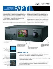
H O M E T H E A T E R A U D I O<br />
<strong>7.1</strong> CHANNEL PREAMP/PROCESSOR<br />
FAP T1
Introduction<br />
Thank you and congratulations on your purchase of the <strong>Fosgate</strong> <strong>Audionics</strong> Preamp/Processor. The FAP T1 combines the best<br />
technologies, components, and software with a clean, user-friendly style, impeccable audio performance and leading edge<br />
capabilities, making it the perfect foundation for any music or home theater system.<br />
This manual contains information on using the FAP T1 Preamp/Processor. It is organized into two sections. “Installation”<br />
covers the location and connection of the <strong>preamp</strong>/<strong>processor</strong> in the system. Like many precision components, careful<br />
attention to the initial setup can yield dividends in higher performance and trouble-free use. “Operation” covers the<br />
controls and features of the <strong>preamp</strong>/<strong>processor</strong>, and how to use them to get the best effect. We strongly urge reading over<br />
the Installation and Operation portions of this manual before putting the FAP T1 into service.<br />
IMPORTANT: The FAP T1 is shipped from the factory in the following default mode:<br />
Output Configuration <strong>7.1</strong><br />
Speaker Size Small<br />
All Crossovers 100Hz<br />
After reading the rest of this manual and determining how your system should be set up, please refer to pages 18-24 to<br />
change these settings.<br />
If your system will be operated in less than a <strong>7.1</strong> <strong>channel</strong> configuration, some DSP modes will not be available to you.<br />
<strong>Fosgate</strong> <strong>Audionics</strong> .... a talented staff of experienced industry professionals.<br />
Jim <strong>Fosgate</strong>, Senior Executive Consultant, one of the most renown surround processing circuit designers in the world, holds<br />
more than 25 patents in the audio industry. His latest efforts include Dolby ® Pro Logic II—acclaimed as a milestone in matrix<br />
surround technology—and the FAVP1 tube surround <strong>processor</strong>/<strong>preamp</strong>. Jim continues to refine his designs in his home audio<br />
laboratories in Utah and Arizona.<br />
Jim Strickland, Vice President of Engineering, has designed some extraordinary products including the famous and highly<br />
regarded Acoustat electrostatic loudspeakers, the trans•nova ® power amplifier series and now the <strong>Fosgate</strong> <strong>Audionics</strong><br />
trans•ana 1000.5 amplifier design. He has been a published AES member since 1970 and holds nine audio patents.<br />
Charles Wood, Executive Consultant, originally founded <strong>Audionics</strong> of Oregon in 1969. In 1986 <strong>Audionics</strong> merged with<br />
<strong>Fosgate</strong> Research to form <strong>Fosgate</strong> <strong>Audionics</strong>. Charles Wood and Jim <strong>Fosgate</strong> have been responsible for many industry<br />
"firsts" in multi-<strong>channel</strong> sound that have been widely adopted throughout the home theater industry.<br />
Gary Church, Chief Acoustic Engineer, has been designing and developing loudspeakers for more than 25 years. His<br />
extensive experience and attention to detail has enabled him to lead a talented engineering team at our Rockford Acoustic<br />
Design (RAD) facility in Michigan.<br />
The Best of All Worlds<br />
<strong>Fosgate</strong> <strong>Audionics</strong>, part of Rockford Corporation, is one of the few companies with the resources to design and<br />
manufacture electronic components and loudspeakers to exacting world-class standards.<br />
<strong>Fosgate</strong> <strong>Audionics</strong> customer support is second to none—a result of years of experience in designing, building and marketing<br />
sophisticated multi-<strong>channel</strong> audio products. We know home theater and multi-<strong>channel</strong> sound inside and out.<br />
Record your FAP T1's serial number and date of purchase here. The serial number is located on the back panel.<br />
Serial Number:<br />
Date of Purchase:<br />
2
Table of Contents<br />
INTRODUCTION ................................................2<br />
SAFETY ............................................................4-5<br />
CONTENTS OF CARTON ....................................6<br />
Unpacking ......................................................6<br />
Contents ..........................................................6<br />
FEATURES ......................................................6-11<br />
Surround Format Information ..........................6<br />
Front Panel ......................................................8<br />
Remote Control ..............................................9<br />
Rear Panel ....................................................10<br />
INSTALLATION CONSIDERATIONS ..................12<br />
INSTALLATION..............................................12-17<br />
Connecting Audio Components ....................13<br />
Connecting Video Components ....................14<br />
FM Antenna ..................................................16<br />
AM Antenna ..................................................16<br />
Connecting an External Amplifier ..................16<br />
Power Connection ........................................16<br />
SYSTEM SETUP ..............................................18-24<br />
Turning ON the Unit ....................................18<br />
Navigating the Setup Menus..........................18<br />
Input Configuration ......................................18<br />
Speaker Configuration ..................................19<br />
Channel Calibration ......................................22<br />
System Configuration ....................................22<br />
Multi–Zone....................................................24<br />
Direct Operation ..........................................24<br />
OPERATION ..................................................25-34<br />
Power ............................................................25<br />
Selecting a Source ........................................25<br />
OPERATION (cont.) ......................................25-34<br />
Volume Control ............................................25<br />
Muting the Volume (Remote Control Only) ..25<br />
Changing the Surround Mode........................26<br />
Surround Data Format Lock ..........................26<br />
Bypass Setting................................................26<br />
Tuner Operation ............................................26<br />
Night Mode ..................................................27<br />
Channel Trim ................................................28<br />
Theater Compensation ..................................28<br />
Multi<strong>channel</strong> Source Playback ......................29<br />
Analog Bass Management..............................29<br />
Setting the FAP T1 Display Brightness............29<br />
Setting the OSD Time Out ............................29<br />
Sleep Timer ..................................................30<br />
Multi–Zone Operation ..................................30<br />
Remote Control Setup and Operation............31<br />
Battery Installation ........................................31<br />
Setup Using Preprogrammed Codes ..............31<br />
Using the Remote Control ............................32<br />
Macro Buttons ..............................................33<br />
Learning Commands from Another Remote ..33<br />
CARE & MAINTENANCE ....................................35<br />
Cleaning ........................................................35<br />
When You Are Away ....................................35<br />
Troubleshooting ............................................35<br />
System Reset..................................................35<br />
SETUP CODES ..............................................36-37<br />
SPECIFICATIONS ................................................38<br />
CONNECTION RECORD CHART ......................39<br />
INDEX............................................................40-41<br />
SERVICE POLICY & LIMITED WARRANTY ........43<br />
3
4<br />
Safety<br />
NOTICE – IMPORTANT SAFETY INFORMATION – PLEASE READ FIRST<br />
CAUTION: To reduce the risk of electric shock, do not remove the<br />
cover. No user service-able parts inside. Refer to qualified personnel.<br />
WARNING: To reduce the risk of fire or electric shock, do not expose<br />
this appliance to rain or moisture.<br />
The lightning flash with arrowhead symbol within an<br />
equilateral triangle is intended to alert the user to the<br />
presence of uninsulated “dangerous voltage” within the<br />
product’s enclosure, that may be of sufficient magnitude to<br />
constitute a risk of electric shock to persons.<br />
The exclamation point within an equilateral triangle is<br />
intended to alert the user of the presence of important<br />
operating and maintenance (servicing) instructions in the<br />
literature accompanying the appliance.<br />
• Read All Instructions – All the safety and operating<br />
instructions of your <strong>Fosgate</strong> <strong>Audionics</strong> equipment should be<br />
read before power is applied to the equipment.<br />
• Retain Owner's Manual – These safety and operating<br />
instructions should be retained for future reference.<br />
• Heed Warnings – All warnings on the unit and in the<br />
operating instructions should be adhered to,<br />
• Follow Instructions – All operating and use instructions<br />
should be followed.<br />
• Cleaning – Unplug the unit from the wall outlet before<br />
cleaning. The unit should be cleaned only as recommended<br />
by the manufacturer.<br />
• Attachments – Do not use attachments not recommended by<br />
the unit manufacturer as they may cause hazards.<br />
• Water and Moisture – Do not use the unit near water-for<br />
example, near a bath tub, wash bowl, kitchen sink, or<br />
laundry tub; in a wet basement; or near a swimming pool.<br />
• Accessories – Do not place the unit on an unstable cart,<br />
stand, tripod, bracket, or table. The unit may fall, causing<br />
serious injury to a child or adult, and serious damage to<br />
the unit. Any mounting of the unit should follow the<br />
manufacturer's instructions, and should use a mounting<br />
accessory recommended by the manufacturer.<br />
• Ventilation – Slots and openings in the cabinet are provided<br />
for ventilation and to ensure reliable operation of the unit and<br />
to protect it from overheating, and these openings must not<br />
be blocked or covered. The openings should never be<br />
blocked by placing the unit on a bed, sofa, rug, or other<br />
similar surface. The unit should not be placed in a built-in<br />
installation such as a bookcase or rack unless proper<br />
ventilation is provided. There should be free space of at least<br />
6 inches (16cm) and an opening behind the unit,<br />
• Grounding or Polarization – The unit may be equipped with<br />
a polarized alternating current line plug (a plug having one<br />
blade wider than the other). This plug will fit into the power<br />
outlet only one way. This is a safety feature. If you cannot<br />
insert the plug fully into the outlet, try reversing the plug. If<br />
the plug should still fail to fit, contact a licensed electrician to<br />
replace your obsolete outlet. Do not defeat the safety purpose<br />
of the polarized plug.<br />
• Power Sources – The unit should be operated only from the<br />
type of power source indicated on the marking label. If you<br />
are not sure of the type of power supplied to your home,<br />
consult your unit dealer or local power company.<br />
• Power-Cord Protection – Power-supply cords should be<br />
routed so that they are unlikely to be walked on or pinched<br />
by items placed upon or against them, paying particular<br />
attention to cords where they enter a plug, or a convenience<br />
receptacle, and the point where they exit from the unit.<br />
• Outdoor Antenna Grounding – If an outside antenna or<br />
cable system is connected to the unit, be sure the antenna or<br />
cable system is grounded so as to provide some protection<br />
against voltage surges and built-up static charges. Article 810<br />
of the National Electrical Code, ANSI/NFPA 70, provides<br />
information regarding proper grounding of the mast and<br />
supporting structure, grounding of the lead-in wire to an<br />
antenna-discharge unit, size of grounding conductors,<br />
location of antenna-discharge unit, connection to grounding<br />
electrodes, and requirements for the grounding electrode,<br />
• Lightning – For added protection for the unit during a<br />
lightning storm, or when it is left unattended and unused for<br />
long periods of time, unplug it from the wall outlet and<br />
disconnect the antenna or cable system. This will prevent<br />
damage to the unit due to lightning and power-line surges.<br />
• Power Lines – An outside antenna system should not be<br />
located in the vicinity of overhead power lines or other<br />
electric light or power circuits, or where it can fall into such<br />
power lines or circuits. When installing an outside antenna<br />
system, take extreme care to keep from touching such power<br />
lines or circuits as contact with them might be fatal.<br />
• Overloading – Do not overload wall outlets, extension cords,<br />
or integral convenience receptacles as this can result in a risk<br />
of fire or electric shock.<br />
• Object and Liquid Entry – Never push objects of any kind<br />
into the unit through openings as they may touch dangerous<br />
voltage points or short-out parts that could result in a fire or<br />
electric shock. Never spill liquid of any kind on the unit.<br />
• Servicing – Do not attempt to service the unit yourself as<br />
opening or removing covers may expose you to dangerous<br />
voltage or other hazards. Refer all servicing to qualified<br />
service personnel.<br />
• Damage Requiring Service – Unplug the unit from the wall<br />
outlet and refer servicing to qualified service personnel under<br />
the following conditions:<br />
When the power-supply cord or plug is damaged,<br />
If liquid has been spilled, or objects have fallen into the unit,<br />
If the unit has been exposed to rain or water,<br />
If the unit does not operate normally by following the operating<br />
instructions. Adjust only those controls that are covered by the<br />
operating instructions as an improper adjustment of other<br />
controls may result in damage and will often require extensive<br />
work by a qualified technician to restore the unit to its normal<br />
operation,<br />
If the unit has been dropped or damaged in any way, and<br />
great care should be exercised in handling, and the unit<br />
should be examined by qualified service personnel.<br />
When the unit exhibits a distinct change in performance-this<br />
indicates a need for service.<br />
• Replacement Parts – When replacement parts are required,<br />
be sure the service technician has used replacement<br />
parts specified by the manufacturer or have the same<br />
characteristics as the original part. Unauthorized substitutions<br />
may result in fire, electric shock, or other hazards.<br />
• Safety Check – Upon completion of any service or repairs to<br />
the unit, ask the service technician to perform safety checks<br />
to determine that the unit is in proper operation condition.
Safety<br />
• Wall or Ceiling Mounting – The unit should be mounted to a<br />
wall or ceiling only as recommended by the manufacturer.<br />
• Heat – The unit should be situated away from heat sources<br />
such as radiators, heat registers, stoves, or other units<br />
(including amplifiers) that produce heat.<br />
IMPORTANT SAFETY NOTE<br />
Before connecting a new component such as the FAP T1 to your<br />
audio or home theater system it is always good practice to make<br />
certain that all components arc turned off, and preferably<br />
unplugged from their AC power source. Many modern electronics<br />
products feature automatic turn-on circuits that may be activated<br />
during an installation, causing the potential for damage to<br />
electronic components and/or speakers. Such damage is not<br />
covered by product warranties and <strong>Fosgate</strong> <strong>Audionics</strong> specifically<br />
disclaims responsibility for any such damage.<br />
Power Cord<br />
The removable power cord that is shipped with the FAP T1 is<br />
specifically designed to be used with this product. DO NOT use<br />
any other power cord, as that may reduce the unit's, performance<br />
and possibly create a safety hazard. In particular, DO NOT use<br />
standard IEC type power cords designed for computers and other<br />
business equipment products, as they have a three prong plug that<br />
is not meant for use with the FAP T1. Should the power cord<br />
require replacement, use an identical type, or contact <strong>Fosgate</strong><br />
<strong>Audionics</strong> for service.<br />
AC Fuse<br />
The fuse is located inside the chassis and is not user-service-able. If<br />
power does not come on, contact your authorized service station.<br />
Tills equipment generates, uses and can radiate radio frequency<br />
energy and, if not installed and used in accordance with the<br />
instructions, may cause harmful interference to radio<br />
communications. However, there is no guarantee that<br />
interference will not occur in a particular installation.<br />
If this equipment does cause harmful interference to radio or<br />
television reception, which can be determined by turning the<br />
equipment off and on, the user is encouraged to try to correct the<br />
interference by one or more of the following measures:<br />
Reorient or relocate the receiving antenna.<br />
Increase the separation between the equipment and receiver.<br />
Connect the equipment into an outlet on a circuit different from<br />
that to which the receiver is connected.<br />
Outdoor Antenna Installation<br />
Safe Antenna and Cable Connection<br />
If an outside antenna or cable system is connected to the equipment,<br />
be sure the antenna or cable system is grounded so as to provide<br />
some protection against built up static charges and voltage surges,<br />
Section 810 of the national Electrical Code, ANSI/NFPA 70 (in<br />
Canada, part 1 of the Canadian Electrical Code) provides information<br />
with respect to proper grounding of the mast and supporting structure,<br />
grounding of the lead-in wire to an antenna discharge unit, size of<br />
grounding conductors, location of antenna discharge unit, connection<br />
to grounding electrodes and requirements for the grounding electrode.<br />
Wiring<br />
Cables that run inside of walls should have the appropriate<br />
markings to indicate compliance with, and listing by the UL, CSA<br />
or other standards required by the UL, CSA, NEC or your local<br />
building code. Questions about cables inside of walls should be<br />
referred to a qualified custom installer, or a licensed electrician or<br />
low-voltage contractor.<br />
Do Not Open The Cabinet<br />
There are no user serviceable components inside this product.<br />
Opening the cabinet may present a shock hazard, and any<br />
modification to the product will void your guarantee. If water or any<br />
metal object, such as a paper clip, coin or a staple, accidentally falls<br />
inside the unit, disconnect it from the AC power source immediately,<br />
and contact <strong>Fosgate</strong> <strong>Audionics</strong> for further instructions.<br />
Recording Copyright<br />
Recording of copyrighted material for other than personal use is<br />
illegal without permission of the copyright holder.<br />
Note to CATV system installer:<br />
This reminder is provided to call the CATV system installer's<br />
attention to Article 820-40 of the NEC, ANSI/NFPA 70, which<br />
provides guidelines for proper grounding and, in particular, specifies<br />
that the cable ground shall be connected to the grounding system of<br />
the building, as close to the point of cable entry as practical.<br />
FCC Information for User<br />
CAUTION: ANY changes or modifications not expressly<br />
approved by the party responsible for<br />
compliance could void the user's authority<br />
to operate the equipment.<br />
Keep Antenna Clear of High Voltage Power Lines or<br />
Circuits<br />
An outside antenna system should be located well away from<br />
power lines, electric light or power circuits and where it will never<br />
come into contact with these power sources if it should happen to<br />
fall. When installing an outside antenna, extreme care should be<br />
taken to avoid touching power lines, circuits or other power<br />
sources as this could be fatal. Because of the hazards involved,<br />
antenna installation should be left to a professional.<br />
NOTE: This equipment has been tested and found to comply with the limits<br />
for a Class B digital device, pursuant to Part 15 of the FCC Rules.<br />
These limits are designed to provide reasonable protection against<br />
harmful interference in a residential installation.<br />
5
Contents of Carton<br />
Unpacking<br />
The carton and packing materials used for your new<br />
Preamp/Processor were specially designed to cushion it from the<br />
shocks and vibration of shipping. Save the carton and packing<br />
materials to use if you move, or if the unit ever needs to be shipped<br />
back to us for any reason.<br />
The FAP T1 is heavy and has many front mounted controls and<br />
rear panel connectors, take care when lifting it so as not to cause<br />
damage.<br />
Features<br />
Your new FAP T1 Preamp/Processor is a state of the art, high<br />
performance audio device. The FAP T1 provides maximum system<br />
connection flexibility with the latest surround processing technologies<br />
assuring compatibility with the widest range of source material.<br />
• 6 Digital Inputs (2 coaxial, 4 optical) – Each input is assignable,<br />
providing comprehensive connectivity.<br />
• 2 Digital Outputs (1 coaxial, 1 optical) – For use with digital recorders<br />
or distribution systems.<br />
• High Bandwidth Professional Quality Component Video Switching –<br />
HDTV compatible component switching for use with digital set top<br />
boxes and progressive scan DVD players.<br />
• 5 Composite and S-Video Inputs – High-quality video circuitry for<br />
connection to your video sources.<br />
• 9 Analog Audio Inputs with Bypass Capability – All analog audio<br />
inputs may be switched to Bypass mode for pure analog sound, or<br />
used with the latest surround processing algorithms.<br />
• Video Output Conversion – Video inputs are automatically converted<br />
from composite to S-Video or vice versa when using these outputs.<br />
NOTE:When possible, always transmit video in it's native<br />
connection format.<br />
• High performance AM/FM/FM Stereo tuner with 32 presets<br />
• Audiophile quality <strong>preamp</strong>lifier stages – Provide maximum<br />
performance for critical audio listening.<br />
• Dolby Digital ® and Dolby Digital EX ® Decoding* – Dolby Digital<br />
decoding delivers 5.1 discrete <strong>channel</strong>s from DVD, satellite, cable<br />
and HDTV sources, while the latest Dolby Digital EX process adds<br />
additional rear surround information for the ultimate home theater<br />
experience.<br />
• Dolby Pro Logic ® II* – The latest surround technology from Dolby<br />
Laboratory, designed by Jim <strong>Fosgate</strong>, delivers 5.1 <strong>channel</strong> sound fields<br />
from matrix-encoded or stereo recordings.<br />
• DTS ® , DTS-ES ® and NEO:6 Decoding** – The full suite of DTS<br />
decoding and processing is available to provide multi<strong>channel</strong><br />
reproduction from virtually any analog source as well as DTS encoded<br />
programs.<br />
• Cirrus Extra Surround ® – The FAP T1 is among the first to offer Cirrus<br />
Extra Surround to provide realistic 6.1 or <strong>7.1</strong> surround sound from<br />
digital and analog sources.<br />
• 5.1 Multi<strong>channel</strong> analog inputs – Connect 5.1-<strong>channel</strong> outputs from a<br />
DVD-A or SACD multi-<strong>channel</strong> player or other multi-<strong>channel</strong> audio<br />
formats to these inputs.<br />
Contents<br />
After unpacking the FAP T1, please check that the following<br />
accessories are in the box:<br />
• Remote Control with Four (4) AAA Batteries<br />
• AC Power Cord<br />
• FM Antenna<br />
• AM Loop Antenna<br />
• Owner's Manual<br />
If for any reason any of the above is missing from your shipment,<br />
please contact <strong>Fosgate</strong> <strong>Audionics</strong> immediately.<br />
• Complete Multi-room System – When properly connected, a second<br />
source may be sent to a remote room, complete with remote volume<br />
control, source selection and tuner control. A trigger for the second<br />
zone allows a second amplifier to turn on and off independently of the<br />
main room. This system may also be used to record an input source<br />
that is different from the one being used in the main room.<br />
• 2 low voltage triggers – One trigger provides automatic turn on/off of<br />
compatible power amplifiers such as the <strong>Fosgate</strong> <strong>Audionics</strong> FAA<br />
1000.5 amplifier or relay-controlled products such as projection<br />
screens, blinds and lighting systems. A separate trigger provides turn<br />
on/off control for an amplifier used with the multi-room system.<br />
* Manufactured under license from Dolby Laboratories.<br />
** Manufactured under license from Digital Theater Systems, Inc. US Pat. No.5,451,942<br />
and other world-wide patents issues and pending.<br />
"Dolby," "Pro Logic" and the double-D symbol are trademarks of Dolby Laboratories.<br />
© 1992-1997 Dolby Laboratories, Inc. All rights reserved.<br />
"DTS" and "DTS Digital Surround" are trademarks of Digital Theater Systems, Inc.<br />
© 1996 Digital Theater Systems, Inc. All rights reserved.<br />
"Extra Surround" is a trademark of Cirrus Logic Inc.<br />
SURROUND FORMAT INFORMATION<br />
The FAP T1 employs the latest technology developed in conjunction<br />
with Cirrus Logic ® , providing one of the most extensive arrays of<br />
surround decoding and processing currently available. You can<br />
choose from Dolby Pro Logic ® II, Dolby Digital ® 5.1,Dolby Digital<br />
EX ® , DTS ® , DTS-ES ® Discrete, DTS-ES ® Matrix, DTS NEO:6 ® and<br />
Cirrus Extra Surround ® . Within each mode, the FAP T1 also offers a<br />
wide range of additional processing options. This means you can<br />
precisely match a surround mode to your program material,<br />
loudspeaker setup and personal taste. In addition, the FAP T1 uses<br />
Cirrus Logic's Triple Crossover ® and Precision Bass Management ®<br />
features to provide maximum flexibility when setting up your audio<br />
surround system (see "System Setup" on page 20 for further details).<br />
The table on the following page lists the surround processing<br />
choices available within each mode. Depending on the selected<br />
source (D-digital or A-analog) and your loud-speaker configuration,<br />
certain processing options may not appear or operate.<br />
Dolby Digital<br />
This digital audio format provides 5.1 -<strong>channel</strong> surround sound.<br />
Dolby Digital source material includes DVDs, Laser Discs, HDTV<br />
broadcasts, some satellite delivered programming, and the output<br />
of some digital cable set top boxes.<br />
6
Features<br />
Display<br />
D A Text Name Description<br />
PLII-C Pro Logic II Cinema<br />
Use for surround enhanced film soundtrack<br />
playback from any 2-Channel source such as VCR<br />
PLII-M<br />
DOLBY PL<br />
PLIIC CR<br />
PLIIM CR<br />
NEO: 6C<br />
NEO: 6M<br />
5 STEREO<br />
7 STEREO<br />
DOLBY D<br />
DOLBY EX<br />
DD CR-C<br />
DD CR-M<br />
DTS<br />
DTS-ES<br />
Pro Logic II Music<br />
Pro Logic Emulation<br />
Pro Logic II Cinema<br />
with Cirrus EX Surr<br />
Pro Logic II Music<br />
with Cirrus EX Surr<br />
DTS NEO:6 Cinema<br />
DTS NEO:6 Music<br />
5-Channel Stereo<br />
7-Channel Stereo<br />
Dolby Digital<br />
Dolby Digital<br />
Surround EX<br />
Dolby Digital with<br />
Cirrus EX Surr Cinema<br />
Dolby Digital with<br />
Cirrus EX Surr Music<br />
DTS<br />
DTS Extended<br />
Surround<br />
For surround enhanced playback of 2-Channel<br />
(stereo) music<br />
Equivilant to original Pro Logic surround<br />
processing with mono surround<br />
Adds Cirrus Extra Surround processing of rear<br />
<strong>channel</strong>s to Pro Logic II Cinema<br />
Adds Cirrus Extra Surround processing of rear<br />
<strong>channel</strong>s to Pro Logic II Music<br />
Creates 6.1 <strong>channel</strong> surround from any<br />
movie-based source<br />
Creates 6.1 <strong>channel</strong> surround from any<br />
music-based source<br />
Creates a 5-Channel program (L/C/R/LS/RS)<br />
from any stereo source<br />
Creates a 7-Channel program (L/C/R/LS/RS/<br />
LSB/LSR) from any stereo source<br />
5.1 <strong>channel</strong> processing for all Dolby Digital<br />
encoded sources<br />
6.1 <strong>channel</strong> processing for soundtrack<br />
encoded with Dolby EX<br />
Adds Cirrus Extra Surround post processing to<br />
Dolby Digital. Creates a rear surround <strong>channel</strong><br />
Adds Cirrus Extra Surround post processing to<br />
Dolby Digital. Creates a rear surround <strong>channel</strong><br />
5.1 <strong>channel</strong> processing for all DTS<br />
encoded sources<br />
5.1 <strong>channel</strong> processing for all sources encoded<br />
with DTS-ES<br />
Dolby Digital Surround EX<br />
Film soundtracks encoded with Dolby Digital Surround EX<br />
technology contain an extra <strong>channel</strong>, added to the soundtrack<br />
during mixing, called Surround Back, which places audio behind<br />
the listener in addition to the existing front left, front center, front<br />
right, surround left, sur-round right, and subwoofer <strong>channel</strong>s. This<br />
additional <strong>channel</strong> provides more detailed imaging behind the<br />
listener creating more depth, spacious ambience and sound<br />
localization than before.<br />
A list of movies created using Dolby Digital Surround EX can be<br />
found on the Dolby web site at www.dolby.com<br />
NOTE:Surround EX mode can also be engaged during the playback<br />
of 5.1 <strong>channel</strong> material that is not Dolby Digital Surround<br />
EX or DTS-ES Matrix or Discrete encoded. When used this<br />
way, signals from the left and right surrounds are used to<br />
synthesize the surround back <strong>channel</strong>. Results using this<br />
method will vary depending on the source material.<br />
Dolby Pro Logic II<br />
Dolby Pro Logic II, designed by Jim <strong>Fosgate</strong>, is a major enhancement<br />
to surround sound systems. In addition to the full range surrounds,<br />
Pro Logic II allows optimum playback of cinema and music<br />
soundtracks. There are three user adjustable options (found in the<br />
menu) that may be adjusted in Pro Logic II Music mode. In addition,<br />
when the Cirrus Extra Surround processing option is engaged for a<br />
<strong>7.1</strong> <strong>channel</strong> playback, these options remain engaged.<br />
Panorama extends the front stereo image to the surround <strong>channel</strong>s.<br />
It is particularly useful when the source material has a narrow<br />
stereo mix.<br />
Dimension allows the front sound-stage to be more coherently<br />
matched with the surround sound-field, particularly to compensate<br />
for differences between the front and surround speakers, and<br />
speaker location. Personal preference becomes the deciding factor<br />
as to how much Dimension to “dial in”.<br />
Center Width allows blending of center front <strong>channel</strong> information<br />
into the front left and right <strong>channel</strong>s. This is particularly useful to<br />
compensate when the center speaker is a different type or design<br />
from that of the left and right speakers. When Center Width is used<br />
to the fullest extent, a phantom center is created.<br />
NOTE:In the Pro Logic II Music Mode time delay is disengaged.<br />
Additionally, Panorama, Dimension and Center Width are<br />
not available in the Pro Logic II Cinema mode. Because the<br />
steering logic dynamics of Pro Logic II Cinema and Music<br />
are identical, many listeners often use the Music mode for<br />
both music and cinema playback.<br />
DTS<br />
This compressed digital data format is similar to Dolby Digital, but<br />
uses a higher data rate. DTS also provides a maximum of 5.1 <strong>channel</strong><br />
surround <strong>channel</strong>s and is available on compact disc, DVD and Laser<br />
Discs. Audio-only DTS discs may be used with any CD, LD or DVD<br />
player with a digital audio output, but DVD discs with DTS audio<br />
must be used on players with the "DTS Digital Out" logo.<br />
DTS-ES<br />
DTS-ES is an extension of the original DTS format that adds an<br />
additional sixth, or center surround, <strong>channel</strong> to a soundtrack.<br />
DTS-ES Matrix titles provide the sixth <strong>channel</strong> by a matrix process,<br />
while DTS-ES Discrete media deliver a true discrete center<br />
surround <strong>channel</strong>. Both DTS-ES formats are backwards compatible<br />
with the original DTS process, and will deliver a 5.1 <strong>channel</strong><br />
output when no center or back surround speakers are available.<br />
The FAP T1 will automatically sense the availability of either<br />
DTS-ES format and automatically switch the processing mode when<br />
required.<br />
DTS NEO:6<br />
This processing mode can create up to 6 full bandwidth <strong>channel</strong>s<br />
from any matrix-encoded 2-<strong>channel</strong> source. Additionally, this mode<br />
can produce the rear surround information from a 5.1 source.<br />
In Music Mode it can expand stereo music material, such as from a<br />
CD, into a multi<strong>channel</strong> surround experience.<br />
Cirrus Extra Surround<br />
This unique decoding algorithm creates 6.1 or <strong>7.1</strong> output from<br />
either matrix-encoded or discrete audio signals. When Cirrus Extra<br />
Surround is selected using either the remote or the front panel<br />
controls the display will show the primary selected mode plus a<br />
CR identifier-such as PL2C-CR. To determine what mode is best for<br />
any specific program material it will be necessary to experiment to<br />
decide what suits your systems and personal taste best.<br />
Stereo<br />
This mode provides conventional 2 <strong>channel</strong> signals to the left and<br />
right front speakers only.<br />
Additional Information<br />
More detailed information about the various surround processing<br />
options contained in the FAP T1 can be found on the following<br />
websites:<br />
www.dolby.com<br />
www.dtsonline.com<br />
www.cirrus.com<br />
7
Features<br />
FRONT PANEL<br />
1 MENU button – Displays menu options on the FAP T1 Display<br />
as well as the On Screen Display (OSD). Press the button again<br />
to exit the Menu mode.<br />
2 (Select) button – Used to select options while in Menu Mode.<br />
3 , , , (Navigation) buttons – Use these buttons to<br />
navigate through and change options while in Menu Mode. Also<br />
used to change settings with some of the front panel controls.<br />
4 REMOTE CONTROL IR SENSOR – Picks up signal from remote<br />
control.<br />
5 FAP T1 DISPLAY – This is a 5” color TFT (Thin Film Transistor<br />
LCD Display) front panel video display. This display replaces the<br />
ordinary two or three line displays found on conventional<br />
<strong>processor</strong>s and receivers. Indicates program source, DSP mode,<br />
tuner preset and/or frequency, digital input, volume level, and<br />
other operating information. Also displays entire full page of the<br />
system menu. This feature can also be used as a mini-TV<br />
monitor for news, weather, data display, or any other viewing<br />
purpose where you may not elect to turn on a full size TV<br />
monitor or projection system.<br />
NOTE:The display is best viewed when set at eye level.<br />
6 SOURCE buttons – Press these buttons to select an input source.<br />
7 VOLUME control – Adjusts the volume level for the main zone<br />
only. Remote zone (Zone 2) is not affected by this control.<br />
8 MULTI ZONE indicator LED – Lights to indicate that the second<br />
zone (Zone 2) is active.<br />
NOTE:This light will remain lit when the other indicators are off, as<br />
long as the second zone is active.<br />
9 On/Standby/Mute indicator LED – Lights to indicate when<br />
the unit is in STANDBY mode and goes out when the<br />
<strong>preamp</strong>/<strong>processor</strong> is active. Also blinks to indicate when the<br />
main volume is muted.<br />
10STANDBY power button – When the main POWER switch on<br />
the rear panel is in the ON position, pressing this button turns<br />
the unit on. The Blue STANDBY/MUTE indicator light goes out.<br />
Pressing this button again returns the Preamp/Processor to<br />
STANDBY mode. The STANDBY/MUTE indicator illuminates.<br />
While in STANDBY mode, the FAP T1 Display is turned off,<br />
control functions are disabled, and all outputs to the main zone<br />
are turned off. However, outputs to the remote zone remain<br />
active and available.<br />
11 TRIM button – Press to select individual output <strong>channel</strong>s to<br />
adjust above or below the master volume level setting from<br />
-15dB to +10dB. Press the or Navigation buttons to<br />
adjust the level for the <strong>channel</strong> indicated, and then press the<br />
TRIM button again to select another <strong>channel</strong>.<br />
12MONITOR button – Press to select through the screen displays<br />
in the following order;<br />
Main: Displays the menu, or whatever composite or S-Video<br />
that is being fed into the main system. Component video feed<br />
will not display and remains free of any internally generated<br />
information.<br />
Zone: Displays any composite video being fed into the Second<br />
Zone (Zone 2).<br />
Security: Displays any composite video being fed into the<br />
Security Video Input.<br />
Blank: Display is turned off completely.<br />
13 (Headphone Output Jack) – This output jack may be used<br />
with a standard size stereo headphones or use an adapter plug<br />
to use stereo headphones or powered media speakers, such as<br />
those used with a computer, that have a smaller plug.<br />
14TUNE UP/TUNE DOWN buttons – When Tuner is selected as<br />
the input source, the Up and Down buttons adjust the tuner's<br />
frequency up or down.<br />
15FM/AM button – Toggles between AM and FM frequency bands.<br />
Pressing this button when listening to any other source<br />
automatically changes the unit's input source to the tuner and<br />
the last station chosen.<br />
8
Features<br />
16PRESET SCAN button – Pressing this button scans the preset<br />
stations in the tuner's memory. Pressing it again stops the scan<br />
at the preset indicated. The unit's input source automatically<br />
changes to Tuner when this button is pressed.<br />
17FM MODE button – Sets the FM Tuner to Mono mode. The letter<br />
"M" appears next to the Tuner Preset number on the FAP T1<br />
Display or the OSD. Pressing the button again returns the FM<br />
Tuner to Stereo mode.<br />
18MEMORY button – Pressing this button when Tuner is selected<br />
as the input source memorizes the current station frequency<br />
into one of the presets. You can preset up to 32 stations.<br />
19ANALOG BYPASS button – Defeats the DSP processing section<br />
and provides an unaltered, full-band-width stereo signal to the<br />
Left and Right <strong>channel</strong> outputs on the rear panel, However, the<br />
subwoofer DSP crossover remains active and bass frequencies<br />
are available at the subwoofer output should you wish to<br />
augment your front LR speaker's low frequency performance.<br />
The word BYPASS appears on the FAP T1 Display or the OSD.<br />
Pressing the button again returns the unit to the previously<br />
selected DSP mode.<br />
20SURROUND MODE buttons – Press this to select from the<br />
various surround modes. Mode availability depends on setup<br />
configuration and input source.<br />
21DIGITAL SELECT button – Press this button to select a digital<br />
input. Each press scrolls to the next input type, as shown on the<br />
FAP T1 Display or the OSD. When ANALOG is shown, the L/R<br />
analog input associated with the input in use will be used.<br />
REMOTE CONTROL<br />
The FAP T1 Universal Learning Remote Control duplicates most functions available<br />
from the front panel of the <strong>preamp</strong>/<strong>processor</strong>. It is designed to access all the<br />
configuration and operation menus of the FAP T1. These are displayed on the<br />
FAP T1 Display, as well as the ON SCREEN DISPLAY (OSD) The Remote Control<br />
contains an extensive library of IR codes and may be programmed to operate a<br />
wide range of audio and video components. Additionally, you can teach the remote<br />
to control other audio/video units not included in the unit's built-in memory by<br />
entering their particular device codes (see pages 34-35).<br />
Many of the buttons on the Remote Control serve several functions, depending on<br />
the source device being controlled. The list below describes each buttons main<br />
functions. For a complete description of their use, refer to "Remote Control Setup<br />
and Operation."<br />
1 Status LED Indicator – Indicates when the remote control is in Programming or<br />
Learning mode and flashes to indicate success or failure of these functions.<br />
2 Source Selection buttons – When the FAP T1 is in Standby mode, pressing one of<br />
these buttons turns the unit on and selects that source as the current input.<br />
If the FAP T1 is already on, pressing one of these buttons selects that source as<br />
the new input.<br />
In both cases, once properly programmed, the remote control operates the source<br />
device selected.<br />
The AUD button tells the Remote to control the FAP T1.<br />
The Source button selected will light whenever you push one of the Remote's<br />
function buttons to indicate that you have sent a command to that component.<br />
If the command pressed is one that typically is not available on that type of unit<br />
(i.e. P SCAN on a CD player) the source button will not light even though you<br />
have pressed that button.<br />
3 POWER button – Returns the FAP T1 to standby mode when the unit is on.<br />
4 MUTE button – Mutes the main volume of the FAP T1. Does not mute the second<br />
zone (Zone 2).<br />
5 Multi-zone button – Press the MULTI button to call up and cycle through the<br />
Multi-zone menu options on the FAP T1 Display and the OSD, if active.<br />
6 TEST button – Outputs an audio test tone for calibrating and setting speaker levels.<br />
Pressing the button again restores the audio output from the previously selected<br />
input source.<br />
7 TRIM button – Activates the Channel Trim function. Pressing the button cycles<br />
through all the <strong>channel</strong>s individually for trim adjustment 10dB above or 15dB<br />
below the master volume setting, in 1dB steps.<br />
8 Numeric Keypad buttons – Use these buttons for control functions requiring you<br />
to enter numbers. For numerals over 10, press the +10 button for every multiple of<br />
ten, followed by a second digit.<br />
9
Features<br />
9 Theater Compensation button – The +10(Hi-EQ) button toggles<br />
Theater Compensation processing on and off.<br />
10Surround/Data Format buttons – Press the , DTS, CR SURR<br />
or STEREO button once to select a surround processing format.<br />
Press the same button again to cycle through the various<br />
processing modes available for the selected format.<br />
Pressing and holding the button for five (5) seconds calls up the<br />
Data Format menu.<br />
11 DIGITAL button – Cycles between the six digital inputs and the<br />
analog input on the FAP T1. The selected input is shown on the<br />
FAP T1 Display and the OSD, if active.<br />
12NIGHT button – Cycles through the various Night dynamic<br />
range compression modes.<br />
13Macro Control buttons – The M1, M2, M3 and M4 buttons are<br />
used to play back macros, which are preprogrammed sequences<br />
of IR commands that you have entered in the remote.<br />
14Tuning and Volume buttons – Use the or CH/TUNE<br />
buttons to adjust the FAP T1 tuner's frequency down or up<br />
when AUD is selected as the input source. These buttons also<br />
operate the tuner or change <strong>channel</strong>s of other devices that are<br />
selected as the current source.<br />
Use the or VOL buttons to adjust the volume of the<br />
FAP T1 from -80dB to +10dB. These buttons also operate the<br />
volume control of other devices that are selected as the current<br />
source.<br />
15MENU button – Calls up the Main Menu on the the FAP T1<br />
Display and the OSD, if active.<br />
16Navigation and Select buttons – Use the four Navigation buttons<br />
to move through menu options shown on the FAP T1 Display or<br />
OSD. Use the SEL button to confirm selections made in menus.<br />
17TONE button – Press this button to select either the Treble or<br />
Bass for adjustment. Once the desired parameter is selected,<br />
use the or navigation buttons to change the setting. The<br />
Treble and Bass can be adjusted ±6dB. Settings are shown on<br />
the on the FAP T1 Display and the OSD, if active.<br />
18Auxiliary Input buttons – Use the AUX 1 and 2 buttons to<br />
select the device connected to one of the two AUX inputs<br />
as the active source.<br />
19 6 Channel Direct button – Pressing the 6 CH button selects as<br />
the source the analog signal from the Multi Channel inputs<br />
(5 <strong>channel</strong>s plus subwoofer) on the FAP T1, as well as<br />
activating the dedicated Bass Management selected by the rear<br />
panel switch. Pressing the button again returns the unit to the<br />
previously selected source.<br />
20BYPASS button – Activates Stereo Bypass mode, sending the signal<br />
from the analog input in use directly to the volume control,<br />
bypassing all digital processing. Pressing the button again returns<br />
the unit to the previously selected mode.<br />
NOTE:In this mode, only 2-Channel audio output will be available.<br />
21AM/FM button – Press this button to select the FAP T1's tuner<br />
as the input source, or to switch between the AM and FM bands<br />
when the tuner is active. Pressing this button when the FAP T1<br />
is in Standby mode will also turn the unit on.<br />
22Tuner Mode button – Press the T.MODE button to switch the FM<br />
tuner between Mono and stereo.<br />
23SLEEP button – Sets the FAP T1's built-in sleep function timer.<br />
24P.SCAN button – Pressing this button scans the AM or FM<br />
stations preset in the tuner's memory. Pressing it again stops the<br />
scan at the preset indicated in the FAP T1 Display.<br />
25Memory button – Press and hold the MEM button to store an<br />
AM or FM station into a preset location. Once the FAP T1<br />
Display begins to flash Memory 01, enter the desired preset<br />
number using the numeric keypad on the remote.<br />
26Light – Illuminates the Remote Control buttons for 7 seconds.<br />
REAR PANEL<br />
Below is a brief explanation of the connections and switches<br />
found on the rear panel of the FAP T1 Preamp/Processor. Before<br />
connecting any audio or video components to the unit, familiarize<br />
yourself with the type and location of connectors available.<br />
1 FM Antenna terminal – Connect the supplied FM antenna or an<br />
external 75Ω antenna.<br />
2 AM Antenna terminals – Connect the supplied AM loop antenna<br />
or an external AM antenna to these terminals.<br />
3 Remote Control jacks – Use the MAIN and ZONE EXT REMOTE<br />
jacks to connect external IR sensors. When the unit is installed<br />
behind doors or where it is not otherwise visible to the remote,<br />
connect an optional, external sensor to the MAIN jack. To<br />
control the FAP T1's Multi-room system from a remote location,<br />
connect an optional remote sensor in the second room to the<br />
ZONE jack<br />
4 Remote Trigger jacks – Use the MAIN and ZONE DC TRIGGER<br />
jacks to control external devices (such as a power amplifier) with a<br />
3-32 VDC trigger input. The device connected to the MAIN jack<br />
will be activated when the FAP T1 is turned on and should be used<br />
for connections to power amplifiers for the main room speakers.<br />
The device connected to the ZONE trigger will only be activated<br />
when the Multi-zone system is turned on. Connect it to the<br />
amplifier used to power the speakers in the second zone (Zone 2).<br />
5 Component Video Input jacks – Use these three (3) sets of jacks<br />
to connect devices with component video outputs such as a<br />
DVD player or HDTV tuner.<br />
6 S-Video jacks – Connect the S-Video output of sources to the<br />
appropriate input jacks. Connect the VCR-OUT jack to the<br />
input of a VCR or other recorder and connect the OUT jack to<br />
an S-Video input on your video display device.<br />
7 Component Video Output jacks – Use these jacks to supply<br />
component video output to an external monitor that accepts<br />
component video signals.<br />
8 Monitor Out (S-Video/RCA Output jacks) – Use these jacks to<br />
connect to the S-Video or RCA input on your video display<br />
device.<br />
9 Digital Outputs – Use the coaxial and optical digital outputs to<br />
connect the <strong>preamp</strong>/<strong>processor</strong> to a device such as CD recorder,<br />
DAT recorder, or other similar device that accepts a digital audio<br />
input.<br />
10
Features<br />
10Security Input jack – Use this input to connect to a security<br />
video camera or any other composite video you wish to display<br />
of the FAP T1 Display. This can be selected to view on the FAP<br />
T1 Display by using the Monitor button.<br />
11 Optical Digital Inputs – Use these inputs to connect the optical<br />
digital audio signal output from such digital devices as CD,<br />
DVD or LD players. These inputs are fully assignable.<br />
12Audio Source Input jacks – Use these inputs for connection to<br />
analog audio sources such as a CD player. One in/out tape loop<br />
is provided for connection to an audio recorder.<br />
13Video Source Input jacks – Use these inputs for connection to<br />
the composite video and analog audio output from sources such<br />
as a DVD or LD player, satellite receiver, cable box, PVR or<br />
other video source. Note that when the Component Video inputs<br />
are used, connect the analog audio outputs of the source to the<br />
DVD or Video 1 jacks, as appropriate.<br />
14VCR jacks – Use these input and output jacks to connect a VCR.<br />
15Multi-zone Output jacks – Use these jacks to supply the analog<br />
stereo audio output to an optional audio amplifier used to power<br />
the speakers in the remote zone.<br />
16Monitor Output jack – Connect this output to the composite<br />
video input of your monitor or other video display device.<br />
17 5.1 Channel Input jacks – Connect the multi<strong>channel</strong> signal from<br />
the analog audio outputs of a device such as a DVD, DVD-A or<br />
SACD to these jacks.<br />
18Amplifier Output jacks – Use the seven audio <strong>channel</strong> output<br />
jacks to connect to an external power amplifier. The eighth jack<br />
supplies the output to a powered subwoofer or external subwoofer<br />
amplifier.<br />
19 5.1 Input Bass Management Control – Setting this switch in the<br />
ON position activates an 80Hz High Pass Filter for the 5.1 <strong>channel</strong><br />
direct input, except the subwoofer. The bass signals from the<br />
5 satellite <strong>channel</strong>s are summed and sent on to the subwoofer<br />
output at all times. Setting the switch in the down position turns<br />
off the High Pass Filter and sends full-range audio to all <strong>channel</strong>s.<br />
This Bass Management Control is totally separate from the<br />
DSP Bass Management set up using the front panel or remote<br />
control.<br />
20Coaxial Digital Input jacks – Use these inputs to connect the<br />
coaxial digital audio signal output from such digital devices as<br />
CD, DVD or LD players. These inputs are fully assignable.<br />
21Product Serial Number – Write this number in the space provide<br />
on page 2 for future reference.<br />
22Main Power switch – Turns the current to the FAP T1 On or Off.<br />
Setting this button to the On position (pushed in) supplies power<br />
to the unit, enabling use of the Standby Power button on the<br />
front panel. When this switch is in the Off position, current is<br />
cut off to the unit.<br />
23AC Input – Use to connect the supplied AC power cord (see<br />
Safety, pages 3-4).<br />
11
Installation Considerations<br />
Installation Location<br />
To assure proper operation and to avoid the potential for safety<br />
hazards, place the unit on a firm and level surface capable of<br />
supporting it's weight. When placing the unit on a shelf, be certain<br />
that the shelf and any mounting hardware can support the weight<br />
of the unit and any additional items in the equipment rack, or on<br />
the shelf.<br />
When positioning the FAP T1 in its final location, make certain<br />
that it has adequate ventilation on all sides, as well as on the top<br />
and bottom. In particular, it is a good idea to provide at least two<br />
or three inches of room above the unit for air circulation. DO NOT<br />
place CDs, DVDs, videotapes, owner's manuals, or other paper on<br />
top of, or beneath, the unit, or in-between multiple amplifiers in a<br />
stack. This will block airflow, causing heat build-up, degraded<br />
performance, and may create a possible fire hazard.<br />
If the unit is to be enclosed in a cabinet or rack, make certain<br />
there is adequate air circulation. Sufficient ventilation should be<br />
provided so that hot air may exit, and cool air may enter the<br />
cabinet. In some instances, a small cooling fan may be required to<br />
insure adequate airflow through the cabinet. If you are in doubt as<br />
to the ventilation requirements for your specific installation, please<br />
contact us. Also, do not place the FAP T1 directly on a carpeted<br />
surface, as this will inhibit airflow underneath as well as create a<br />
potential fire hazard.<br />
Avoid installation in humid locations, in extremely hot or cold<br />
locations, or in areas that are exposed to direct sunlight or space<br />
heating equipment.<br />
Installation<br />
Before proceeding, please observe the following precautions when<br />
connecting devices to your new FAP T1.<br />
• Do not plug the power cord into your FAP T1 until all other<br />
connections have been made.<br />
• Always refer to the instructions that came with the<br />
component that you are connecting for specific procedures,<br />
warnings and options.<br />
• For all analog connections, the red input jacks (R) are used<br />
for the right <strong>channel</strong>, white input jacks (L) are used for the<br />
left <strong>channel</strong>, and yellow input jacks (V) are used for the<br />
composite video connection.<br />
• Make sure to insert all plugs and connectors securely.<br />
Improper connections can result in noise, poor performance,<br />
or damage to the equipment.<br />
• Do not bundle audio/video connection cables with power<br />
cords and speaker cables. Doing so may adversely affect the<br />
picture and sound quality. For example, run all the power<br />
cords down one side of the cabinet, all the signal cords down<br />
the other side, and the speaker wires down the center.<br />
• When connecting devices to the digital inputs and outputs,<br />
you may also consider hooking up the analog connections to<br />
and from the components to insure that all signals can be<br />
employed by the <strong>preamp</strong>/<strong>processor</strong>.<br />
• When using the optical input or output jacks, remove the<br />
protective cap and keep it in a safe place. When these jacks<br />
are not in use the protective cap should be replaced.<br />
• When using an optical input or output jack, always use a<br />
high-quality optical fiber cable.<br />
IMPORTANT:We strongly recommend that before you connect any<br />
loudspeakers to your amplifiers, you complete all<br />
needed connections and set up procedures to your<br />
FAP T1 as outlined below. This will reduce the<br />
chance that a mis-connection or other error will<br />
produce audio output that might damage your<br />
speakers or other components.<br />
Gives, the wide variety of components that can be connected to<br />
your FAP T1, there are numerous ways in which your system can<br />
be assembled. To help you with this task, use the chart at the end<br />
of this manual to record the components connected to your unit, as<br />
well as which type of input (analog, coaxial, S-Video, etc.) is used.<br />
Keep this chart for future reference.<br />
There are many possible ways to connect a particular device.<br />
Use the diagrams on the following pages as a guideline. The<br />
information in this section contains some of the more common<br />
situations you might encounter in your system. Always consult the<br />
owner's manual that came with the component you are connecting<br />
for more information on the source component's connections.<br />
12
Installation<br />
Connecting Audio Components<br />
CONNECTING AUDIO COMPONENTS<br />
CD Player<br />
Analog: Connect the L and R <strong>channel</strong> outputs on the CD player to<br />
the CD IN jacks on the FAP T1.<br />
Digital: If your CD player has a digital output jack, connect it to<br />
one of the coaxial (COAX 1 or 2) or optical (OPT 1-4) input jacks<br />
on the <strong>preamp</strong>/<strong>processor</strong>, depending on the type of connector used<br />
by the CD player. Later, you will con-figure the FAP T1 to use the<br />
specific input that you have chosen. For now, note which digital<br />
input you connected to on your system chart.<br />
Audio Recorder<br />
A recording device such as a cassette deck, MD recorder, DAT<br />
deck or CD recorder can be connected to the FAP T1 using either<br />
or both of the following methods.<br />
Analog: Connect the L and R audio outputs on the recorder<br />
(usually marked PLAY) to the TAPE IN jacks on the rear of the<br />
<strong>preamp</strong>/<strong>processor</strong> and connect the L and R audio inputs (usually<br />
marked REC) to the TAPE OUT jacks of the FAP T1.<br />
Digital: If your recorder has a digital output jack, connect it to one<br />
of the coaxial (COAX1 or2) or optical (OPT1-4) input jacks on the<br />
<strong>preamp</strong>/<strong>processor</strong>, depending on the type of connector used by the<br />
device. Later, you will configure the FAP T1 to use the specific<br />
input that you have chosen. For now, note which digital input you<br />
connected to on your system chart.<br />
If your recorder has a digital input jack, connect it to either the<br />
coaxial or optical output jack on the <strong>preamp</strong>/<strong>processor</strong>. The signal<br />
from the selected digital input source of the FAP T1 will be sent to<br />
the recorder.<br />
13
Installation<br />
Connecting Video Components<br />
CONNECTING VIDEO COMPONENTS<br />
Before making connections to any video devices, understand how<br />
the FAP T1 routes the video portion of the signal through its video<br />
section.<br />
• Any signal that appears at one of the composite video input<br />
jacks (DVD, VIDEO 1, 2 or 3) is automatically sent to the<br />
composite video OUT and VCR OUT jacks, as well as the<br />
S-Video OUT and VCR OUT jacks.<br />
• Any signal that appears at the S-Video input jacks (DVD,<br />
VIDEO 1, 2 or 3) is automatically sent to the S-Video OUT<br />
and VCR OUT jacks, as well as the composite video OUT<br />
and VCR OUT jacks.<br />
• Any signal that appears at the component video (DVD or<br />
VIDEO 1) input jacks is automatically sent to the component<br />
video MONITOR OUT connection only.<br />
NOTE:To provide the greatest signal flexibility, connect all<br />
available types of inputs and outputs from your video<br />
devices. For example, if only the composite video output<br />
(yellow RCA jack) connection is made to your display<br />
device, component sources will not be available, even if<br />
they are connected to the FAP T1.<br />
DVD Player<br />
Composite: Connect the composite video output from the DVD<br />
player to the DVD video input jack on the rear of the FAP T1 using<br />
an RCA-type video cable.<br />
S-Video: If there is an S-Video output on the DVD player, and you<br />
have an S-Video input on your TV or monitor, connect it to the<br />
S-Video DVD input on the rear of the FAP T1 using an S-Video<br />
cable. S-Video delivers a better picture than composite connections<br />
and should be used whenever possible unless you can use<br />
component connections, which deliver better video than S-Video.<br />
Component: If the DVD player has component video outputs,<br />
connect them to the DVD component video input jacks on the rear<br />
of the FAP T1 using an appropriate cable set.<br />
Analog Audio: Connect the L and R <strong>channel</strong> outputs on the DVD<br />
player to the DVD IN audio jacks on the rear of the FAP T1.<br />
Digital Audio: Connect one of the digital output jacks on the DVD<br />
player to one of the coaxial (COAX I or 2) or optical (OPT 1-4)<br />
input jacks on the rear of the <strong>preamp</strong>/<strong>processor</strong>, depending on the<br />
type of connector used by the DVD player. Later, you will<br />
configure the FAP T1 to use the specific input that you haw<br />
chosen. For now, note which digital input you connected to on<br />
your system chart.<br />
14
Installation<br />
Multi-<strong>channel</strong> Audio If your DVD player supplies a multi-<strong>channel</strong><br />
audio output (for DVD Audio or SACD playback), connect the six<br />
outputs (special cable sets for this are available from numerous<br />
sources) from your player to the six input jacks labeled MULTI<br />
CHANNEL INPUT on the rear panel of the FAP T1. Be sure match<br />
the connections—left to left, right surround to right surround, and<br />
so on. If your player includes a built-in Dolby Digital decoder and<br />
has 5.1 <strong>channel</strong> analog audio outputs we suggest that you do not<br />
use them, but use the digital audio connection and the FAP T1's<br />
internal decoders instead.<br />
If you are connecting a DVD-Audio or SACD player to the FAP T1<br />
using these jacks, you will need to consider the setting for the<br />
Analog Bass Management switch on the FAP T1's rear panel. If<br />
your system uses all full range speakers, set. the switch in the OFF<br />
position. In that setting the signal will be routed directly from the<br />
input jacks to the volume control.<br />
However, if your system uses small,<br />
frequency-restricted satellite speakers, the<br />
switch should be set to the ON position. In<br />
that setting the signals sent to the main<br />
speakers will be cut at 80 Hz and a summed<br />
bass signal will be sent to the subwoofer<br />
output. Note that you should place this<br />
switch in the OFF position if your playback<br />
source includes internal bass management<br />
circuitry.<br />
Video Recorder<br />
A video recording device such as a VCR, PVR (such as a TiVo ® ,<br />
Replay ® , Uiti-mate TV ® , DishPlayer ® or similar device) or DVD<br />
recorder can be connected to the FAP T1 using the following<br />
methods.<br />
Composite: Connect the composite video output from the<br />
recording device to the VCR IN composite video jack on the rear of<br />
the <strong>preamp</strong>/<strong>processor</strong>. Connect the recording device's composite<br />
video input to the VCR OUT composite video jack of the FAP T1<br />
using an RCA-type video cable.<br />
S-Video: If there is an S-Video output on the recording device,<br />
connect it to the S-Video VCR IN input on the rear of the<br />
<strong>preamp</strong>/<strong>processor</strong> and connect the S-Video input to the S-Video<br />
VCR OUT using an S-Video cable. S-Video delivers a better picture<br />
than composite connections and should be used whenever possible<br />
unless you can use component connections, which deliver better<br />
video than S-Video.<br />
Component: If the recording device has component video outputs,<br />
connect them to one of the component video input jacks (DVD or<br />
VIDEO 1) on the rear of the <strong>preamp</strong>/<strong>processor</strong> using an appropriate<br />
cable set.<br />
Analog Audio: Connect the L and R audio outputs on the recorder<br />
to the VCR IN audio jacks on the rear of the <strong>preamp</strong>/<strong>processor</strong> and<br />
connect the L and R inputs of the recorder to the VCR OUT audio<br />
jacks on the FAP T1.<br />
Digital Audio: If your recording device also has a digital audio<br />
output jack, connect it to one of the coaxial (COAX 1 or 2) or<br />
optical (OPT 1-4) input jacks on the rear of the <strong>preamp</strong>/<strong>processor</strong>,<br />
depending on the type of connector used by the device. Later, you<br />
will configure the FAP T1 to use the specific input that you have<br />
chosen. For now, note which digital input you connected to on<br />
your system chart.<br />
If your recording device also has a digital input jack, connect<br />
it to either the coaxial or optical output jack on the rear of the<br />
<strong>preamp</strong>/<strong>processor</strong>, depending on the type of connector used by<br />
the device. The signal from the selected input source of the<br />
FAP T1 will be sent to the recorder.<br />
Video Display<br />
A video display device such as a television monitor, fixed-pixel<br />
device (plasma or LCD) or video projector can be connected to the<br />
FAP T1 using the following methods.<br />
Composite: Connect the composite video input from the display to<br />
the composite video OUT jack on the rear of the FAP T1 using an<br />
RCA-type video cable.<br />
S-Video: If there is an S-Video input on the display, connect it to<br />
the S-Video OUT jack on the rear of the <strong>preamp</strong>/<strong>processor</strong> using an<br />
S-Video cable. S-Video delivers a better picture than composite<br />
connections and should be used whenever possible unless you can<br />
use component connections, which deliver better video than S-Video.<br />
Component: If the display has component video inputs, connect<br />
them to the component video MONITOR OUT jacks on the rear of<br />
the FAP T1 using an appropriate cable set.<br />
NOTE: Since the FAP T1 converts composite video to S-Video and<br />
vice versa, you need only make one of those two types of<br />
connections between the FAP T1 and your video display.<br />
However, when component video connections are used it is<br />
still necessary to make either the composite or S-Video<br />
connections so that you are able to view the on-screen<br />
menus and displays which do not appear on the component<br />
outputs. The FAP T1 does not convert from either composite<br />
or S-Video to component or vice versa.<br />
Satellite Tuner or Television<br />
Composite: Connect the composite video output from the satellite<br />
tuner or television to one of the video input jacks (VIDEO 1,2 or 3)<br />
on the rear of the FAP T1 using an RCA-type video cable.<br />
S-Video: If there is an S-Video output on the satellite tuner or<br />
television, connect it to one of the S-Video inputs (VIDEO 1,2 or 3)<br />
on the rear of the FAP T1 using an S-Video cable. S-Video delivers<br />
a better picture than composite connections and should be used<br />
whenever possible unless you can use component connections,<br />
which deliver better video than S-Video.<br />
Component: If the satellite tuner or television has component video<br />
outputs, connect them to one of the component video input jacks<br />
(DVD or VIDEO 1) on the rear of the FAP T1 using an appropriate<br />
cable set.<br />
Analog Audio: Connect the L and R <strong>channel</strong> outputs on the satellite<br />
tuner or television to the set of audio input jacks (VIDEO 1, 2 or 3)<br />
directly under the video jack used on the rear of the FAP T1.<br />
Digital Audio: If your satellite tuner or television has a digital<br />
output jack, connect it to one of the coaxial (COAX 1 or 2) or<br />
optical (OPT 1-4) input jacks on the rear of the <strong>preamp</strong>/<strong>processor</strong>,<br />
depending on the type of connector used by the device. Later, you<br />
will configure the FAP T1 to use the specific input that you have<br />
chosen. For now, note which digital input you connected to on<br />
your system chart.<br />
15
Installation<br />
FM Antenna<br />
Connect the supplied FM antenna to the terminal labeled FM75Ω.<br />
Do not over tighten as this may damage the connection.<br />
The supplied FM antenna is for indoor use only. For best signal<br />
reception you must fully extend the antenna. Experiment with the<br />
antenna's position to obtain the strongest signal. You can attach it<br />
to a wall or other surface using push pins or similar apparatus.<br />
If FM reception is poor with the supplied indoor antenna, the use<br />
of an amplified indoor or outdoor antenna is recommended.<br />
NOTE:You can only connect a 75Ω type FM antenna to the<br />
FAP T1. If you choose to use an antenna other than the<br />
one supplied, be sure to verify that it has the correct type of<br />
connector or that you obtain an appropriate adapter.<br />
Try to ovoid using the same antenna for both FM and TV<br />
reception since the signals can interfere with each other. If<br />
you must use a com-mon FM/TV antenna, be sure that you<br />
install an splitter to separate the two signals.<br />
AM Antenna<br />
Connect the AM antenna to the terminals labeled AM and E(arth)<br />
on the rear panel of the <strong>preamp</strong>/<strong>processor</strong>. Start by pressing the<br />
lever on the side of one of the terminals to the right. Next, insert<br />
one of the antenna wires into the opening. Finish by returning the<br />
lever to the up position, securing the wire. Do the same for the<br />
other wire to complete installation.<br />
FM Antenna<br />
Connecting an External Amplifier<br />
AM<br />
Loop<br />
Antenna<br />
IMPORTANT:Before attempting to plug any jacks into any power<br />
amplifier verify that the power amplifier is turned off<br />
and/or disconnected from the AC mains. Failure to do<br />
so can potentially result in severe damage to your<br />
amplifier and loudspeakers.<br />
Use the audio jacks labeled OUTPUT to connect the FAP T1 to an<br />
external power amplifier such as the <strong>Fosgate</strong> <strong>Audionics</strong> FAA 1000.5<br />
Power Amplifier. The FAP T1 can output up to <strong>7.1</strong> <strong>channel</strong>s of<br />
sound (seven satellite and one subwoofer <strong>channel</strong>) depending on<br />
source components and material.<br />
The output jacks supplied by the FAP T1 are: left Front, Center,<br />
Right Front, Left Surround, Right Surround, Left Surround Back,<br />
Right Surround Back, and Subwoofer.<br />
Be sure to verify that the correct outputs are connected to the<br />
appropriate input jacks (Left Front to Left Front, Right Surround<br />
Back to Right Surround Back, etc.)<br />
When a powered subwoofer is used, connect the Subwoofer output<br />
jack to the Line Input jack on your subwoofer and follow any<br />
specific connection and/or configuration, instructions supplied with<br />
the subwoofer. If your subwoofer is a passive speaker, connect the<br />
subwoofer output jack on the FAP T1 to the input of the amplifier<br />
used to power the subwoofer, and then connect the subwoofer<br />
speaker itself to the amplifier.<br />
Second Zone (Zone 2)<br />
Use the L and R <strong>channel</strong> ZONE OUT audio jacks to connect the<br />
FAP T1 to the analog audio inputs of an external amplifier or other<br />
audio component in a second zone. The signal present will reflect<br />
the input selection of the FAP T1. This may be adjusted using the<br />
Zone Menu or the MULTI button on the remote control.<br />
Power Control Connections<br />
The DC TRIGGER jacks are used to remotely turn-on other devices<br />
in your system when the FAP T1 is powered on. Power is applied<br />
to the MAIN Trigger Output jack when the FAP T1 is turned on<br />
from the Standby Mode. We recommend that this jack be used to<br />
turn on a compatible power amplifier such as those available from<br />
<strong>Fosgate</strong> <strong>Audionics</strong>, but it may also be used to activate compatible<br />
products such as projection screens or motorized blinds.<br />
Connect a 3.5mm mono mini-plug between the DC Trigger MAIN<br />
jack on the rear panel of the FAP T1 and the low voltage trigger<br />
jack of the device to be controlled to enable remote turn-on of<br />
that component. The ZONE Trigger jack is activated when the<br />
Multi-room system is turned on and should be used for control of<br />
amplifiers used to power the speakers installed in the remote zone.<br />
It will remain activated as long as the Multi-room system is on,<br />
even when the FAP T1 is in the Standby mode for the main room.<br />
Remote Control<br />
The EXT REMOTE jacks allow you to extend the on-board<br />
remote control sensor on the FAP T1's front panel so that you may<br />
continue to control the FAP T1 even when it is installed behind<br />
solid or smoked cabinet doors or when the front panel sensor is<br />
otherwise not visible to the remote control.<br />
To extend the remote sensor connect an optional remote sensor to<br />
the MAIN jack.<br />
The ZONE jack is provided to enable remote control of the<br />
FAP T1's multi-zone system through the use of an optional remote<br />
sensor in the second zone. Connect the sensor to the ZONE jack<br />
using a 3.5mm mono mini-plug and the wiring specified by the<br />
sensor's manufacturer.<br />
Power Connection<br />
Insert the supplied power cord into the AC input of the rear panel<br />
of the <strong>preamp</strong>/<strong>processor</strong>. Do not use a power cord other than the<br />
one supplied with the FAP T1. It's designed for use with the<br />
FAP T1 and should not be used with any other device.<br />
CAUTION: Before you plug the power cord into an AC<br />
wall outlet, ensure all connections to the<br />
<strong>preamp</strong>/<strong>processor</strong> have been made correctly.<br />
WARNING: Never disconnect the power cord from the<br />
FAP T1 while the other end is plugged into<br />
an AC outlet. Doing so may cause an electric<br />
shock. Always connect power by plugging<br />
into the AC outlet last and disconnect by<br />
unplugging from the AC outlet first.<br />
16
Installation<br />
Connecting an External Amplifier<br />
Connecting to an External Amplifier in a Second Zone (Zone 2)<br />
17
System Setup<br />
At this point you should have made all the necessary physical<br />
connections between the FAP T1 and your source equipment,<br />
amplifiers and speakers. All that remains is to properly configure the<br />
system to reflect your specific equipment and room characteristics.<br />
3. Press or to select the item to be adjusted. Then press<br />
or to adjust a selected item.<br />
To turn the FAP T1 on:<br />
1. Plug the cord into an AC wall outlet or UL approved power<br />
strip or surge protection device.<br />
Make certain that the AC power cord supplied with the FAP T1<br />
is firmly inserted into the socket on the unit's rear panel.<br />
2. Press the rear panel POWER switch to the On position to<br />
set the FAP T1 to Standby mode.<br />
The Standby Indicator on the Front Panel will light up.<br />
3. Press the front panel Standby Power button to turn on the<br />
FAP T1 or press the AUD button on the remote control.<br />
The FAP T1 DISPLAY will light up and the standby indicator<br />
will turn off.<br />
Navigating the Setup Menus<br />
Setup of the FAP T1 can be performed from the front panel of the<br />
unit, or by using the remote control. Information is shown on the<br />
FAP T1 Display, or the On Screen Display (OSD). All selections<br />
are made using a combination of the following buttons:<br />
Front Panel: The MENU, Navigation ( , , and ) and<br />
(Select) buttons left of the FAP T1 Display<br />
Remote Control: The MENU, Navigation ( , , and ) and<br />
SEL/PLAY buttons in the center of the remote.<br />
These buttons will be referred, unless otherwise specified, when<br />
navigating the Setup Menus.<br />
The following example demonstrates how to navigate the FAP T1<br />
menu system in general using the Speaker Configuration menu as<br />
an illustration. For detailed information on a specific part of the<br />
setup process, consult the pages relating to that topic.<br />
To use the FAP T1 menu system:<br />
NOTE:The following selected menus appear on the FAP T1<br />
Display and the OSD (On Screen Display)<br />
Once you have made your selections, you can use the and to<br />
return to the Main Menu and/or exit the menu system. Alternatively,<br />
pressing the MENU button once will return you to the Main Menu.<br />
Pressing the MENU button a second time will exit the menu system.<br />
Note that the menus will remain visible on the FAP T1 Display and<br />
OSD until you exit the menu system.<br />
IMPORTANT:When viewing static images such as on screen menus<br />
or video game images using a CRT-based projector,<br />
plasma display or direct-view CRT monitor or<br />
television, there is a risk of permanently 'burning in"<br />
the image. Do not leave these images on for an<br />
extended period of time. This type of damage is not<br />
covered by the <strong>Fosgate</strong> <strong>Audionics</strong> FAP T1 warranty.<br />
INPUT CONFIGURATION – Setup and Selection<br />
Before calibrating your FAP T1 and adjusting loudspeaker setup<br />
and configuration, you should first set up the sources connected to<br />
it. You will make your selections using the Input Configuration<br />
menu, shown below.<br />
NOTE:The following selected menus appear on the FAP T1<br />
Display and the OSD (On Screen Display)<br />
Figure 1<br />
Because of the extensive options<br />
available for each input source,<br />
we strongly recommend you use<br />
the chart at the end of this manual<br />
to record the settings for each<br />
input and component. Later, if<br />
you re-configure your system, this<br />
chart will help avoid confusion.<br />
1. Press the MENU button to display the Main Menu.<br />
2. Press or to select a Setup menu. Then press<br />
(Select) to enter into the menu.<br />
To configure an input:<br />
1. Press the MENU button to enter the Main Menu.<br />
The Main Menu appears and the cursor should be pointing to<br />
INPUT CONFIG.<br />
2. Press (Select) to enter the Input Configuration menu.<br />
The Input Configuration menu appears and the cursor should be<br />
pointing to SOURCE.<br />
18
System Setup<br />
3. Use the and buttons to change the Source you wish<br />
to configure.<br />
The Source choices appear as follows as you scroll through<br />
them:<br />
DVD > VIDE01 > VIDE02 > VIDE03 > VCR ><br />
TUNER (FM) > TUNER (AM) > CD > TAPE > AUX1 > AUX 2<br />
You can scroll in either direction using the and buttons.<br />
4. Press the button once to select INPUT.<br />
5. Use the and buttons to change the Input for that<br />
source.<br />
The input choices appear as follows as you scroll through them:<br />
ANALOG > OPTICAL1 > OPTICAL2 > OPTICAL3 ><br />
OPTICAL4 > COAXIAL1 > COAXIAL2<br />
You can scroll in either direction using the and buttons.<br />
If you connected the source to the Analog inputs, select:<br />
ANALOG.<br />
If you connected the source to one of the Optical Digital inputs,<br />
select the appropriate one by choosing: OPTICAL 1, 2, 3, or 4.<br />
If you connected the source to one of the Coaxial Digital inputs,<br />
select the appropriate one by choosing: COAXIAL 1 or 2.<br />
NOTE:Always connect and configure the digital input source<br />
option if available from the specific component, as this will<br />
provide maximum performance and best sound quality.<br />
Remember that you can always return to any menu to change<br />
your selection, should that be required.<br />
6. Press the button once to select MODE.<br />
7. Use the and buttons to change the Mode for that<br />
source.<br />
The available surround modes appear as follows as you scroll<br />
through them:<br />
PLII CINEMA > PLII MUSIC > DOLBY PRO LOGIC ><br />
7 STEREO > 5 STEREO > STEREO > PLII CINEMA+CS<br />
> PLII MUSIC+CS > DTS > DTS NEO:6 CINEMA ><br />
DTS NEO:6 MUSIC > DOLBY DIGITAL ><br />
DOLBY DIGITAL EX > DTS ES<br />
You can scroll in either direction using the and buttons.<br />
You should choose a surround mode to be the default for this<br />
source. Please refer to the table on page 7 for a detailed listing<br />
of all options. Remember that all available mode options can be<br />
selected for a Digital input source, but certain modes will not be<br />
available through the Analog input for that source.<br />
Selecting the default mode will not exclude other modes of<br />
surround decoding. In fact, certain digital signals (Dolby Digital,<br />
DTS, some Dolby Digital EX, and others) contain a special<br />
digital "flag" that tells the FAP T1 to switch to that surround<br />
mode. When the FAP T1 receives one of these bitstreams it<br />
will switch to that mode of operation. Additionally, you can<br />
manually cycle through the available modes while the source is<br />
playing to choose the one you wish to use.<br />
8. Press the button once to select TREBLE<br />
9. Use the and buttons to adjust the Treble.<br />
Treble boost can be adjusted from -6dB to +6dB in 2dB<br />
increments (default is 0dB).<br />
10.Press the<br />
button once to select BASS.<br />
11.Use the and buttons to adjust the Bass.<br />
Bass boost can be adjusted from -6dB to +6dB in 2dB<br />
increments (default is 0dB).<br />
NOTE:Any tone control setting you make in this mode are global,<br />
and will affect all input sources and all output <strong>channel</strong>s.<br />
They will remain in effect until you go back into the setup<br />
menu and change them or change them using the TONE<br />
button on the remote control.<br />
12.Press the<br />
button to select NIGHT.<br />
NOTE:This option only operates with a Dolby Digital or Dolby<br />
Digital EX source and one of these modes is active.<br />
This option allows you to set the amount of Dynamic Range<br />
Compression used when the FAP T1 is placed into the NIGHT<br />
mode. This mode can also be selected by pressing the NIGHT<br />
button on the remote control.<br />
There are two types of automatic compression control built into the<br />
Dolby Digital process. Compression makes the loud parts softer and<br />
the soft parts louder to reduce the difference between the two.<br />
One type of compression is most useful for situations such as late<br />
night viewing of programs with a wide dynamic range (like many<br />
action movies) that might disturb others in your home. This function<br />
can also be used to provide compression for program material that<br />
may require enhancement of overall intelligibility (such as some<br />
older soundtracks). Another feature provided by this option is the<br />
necessary peak limiting required to avoid signal overload when<br />
"down-mixing" functions are selected.<br />
The second variable provides additional peak limiting to allow<br />
overall average program level to be increased by adding even more<br />
compression to the signal.<br />
These two algorithms can provide sufficient overall gain reduction to<br />
allow even wide dynamic range soundtracks with very soft parts and<br />
very loud parts to maintain good audibility at low volume levels.<br />
In most cases a minimum amount of dynamic range reduction is<br />
automatically included in the bitstream to ensure safe down-mixing.<br />
13.Use the and buttons to select a Dynamic Range<br />
option you prefer for the Night setting,<br />
NO COMP This option leaves the compression at 0% change.<br />
DR COMP1 This option increases the compression by 25%.<br />
DR COMP2 This option increases the compression by 50%,<br />
DR COMP3 This option increases the compression by 75%.<br />
DR COMP4 This option increases the compression by 100%.<br />
Each option increases the amount of Dynamic Range compression<br />
to the signal. Depending on your family, neighbors, circumstances,<br />
and the overall volume you wish to achieve, we recommend you<br />
start with DR COMP1 or DR COMP2 as your initial setting. You<br />
will have to experiment with program material and your personal<br />
preferences to determine what is acceptable and best for you.<br />
14.Press the button to select RETURN TO MAIN MENU.<br />
15.Press the (Select) or MENU button to return to the Main<br />
Menu, or press the MENU button twice to exit the menu<br />
system.<br />
NOTE:Except for the input source and surround mode, the settings<br />
chosen during this input setup process are universal and<br />
apply to all sources. You will need to correctly set each<br />
digital source to the appropriate input and select a default<br />
surround mode for each source connected to your FAP T1.<br />
Once you have completed these selections, proceed to<br />
the next step: configuring your loudspeaker setup and<br />
calibrating your system.<br />
19
System Setup<br />
SPEAKER CONFIGURATION – Setup and Selection<br />
You are now ready to configure the FAP T1 for your particular<br />
loudspeaker system. Before proceeding please read the following<br />
information carefully:<br />
Speaker Placement<br />
The best speaker placement for your particular room will depend<br />
on its size, furnishings, seating arrangement, the acoustical<br />
properties of the space, including wall type, coverings, and various<br />
other factors.<br />
Due to the complex nature of these variables it is impossible to<br />
recommend any one-size-fits-all placement. You may well have to<br />
experiment with various placement options to determine the best<br />
configuration for your specific situation. Please note that, the<br />
configuration and placement of your speakers is critical for creating<br />
the best possible surround sound playback.<br />
Here are some basic recommendations you should consider when<br />
positioning your speakers.<br />
Front left, center and right speakers:<br />
• These speakers should be placed at the same relative height<br />
from the floor and a similar distance from any walls. Most<br />
speakers sound best when located with the tweeter at ear<br />
height when you're seated. Typically, the further away from<br />
the walls the speakers are, the better they will sound.<br />
• Insure that the speakers are aimed at the listener's ears within<br />
your chosen seating position.<br />
Surround left and right speakers<br />
• Place these speakers so that their height is approximately<br />
3 feet (1 meter) higher than that of the listener's ears if feasible.<br />
Surround back left and right speakers<br />
These speakers are required for Surround EX, DTS-ES, DTS NEO:6<br />
and Cirrus Extra Surround playback.<br />
• Place these speakers behind the listener so that the angle between<br />
each speaker and the listener is approximately 30 degrees.<br />
• Place these speakers so that their height is 3 feet (1 meter)<br />
higher than that of the listener's ears.<br />
Note on dipole surround loudspeakers: Most dipole surround<br />
speakers have an arrow which indicates their proper<br />
orientation relative to your video display/screen. Dipoles<br />
placed on side walls should have the arrows pointing<br />
forward. Dipoles placed on a rear or back wall should<br />
have the arrows pointing towards each other to achieve the<br />
correct acoustical image in the room.<br />
Subwoofer<br />
Subwoofer placement can frequently be a trial and error affair as bass<br />
energy set up "standing waves" in most every room. These standing<br />
waves can cause areas with too much bass, areas with too little bass,<br />
and areas in between. You may have to move the subwoofer and or<br />
the prime listening area to improve the bass response. Be aware that<br />
every surface you place the woofer close to (one wall, floor, two walls<br />
in a comer) will increase the overall apparent bass in the room. But<br />
this can potentially lead to boomy and muddy<br />
sounding bass.<br />
When connecting any speakers, be sure to read the<br />
instruction manuals that came with the product and<br />
check your power amplifier's instruction manual for<br />
proper hook-up of the loudspeakers.<br />
IMPORTANT: The FAP T1 is shipped from<br />
the factory in the following<br />
default mode:<br />
Output Configuration <strong>7.1</strong><br />
Speaker Size<br />
All Crossovers<br />
Small<br />
100Hz<br />
20
System Setup<br />
To configure the FAP T1 for your speaker system:<br />
The first step in configuring the FAP T1 to operate with your<br />
speaker system is to set the type, number and crossover frequencies<br />
of your particular loudspeakers. You make these selections using<br />
the Speaker Configuration menu shown below.<br />
NOTE:The following selected menus appear on the FAP T1<br />
Display and the OSD (On Screen Display)<br />
Figure 2<br />
1. Press the MENU button to enter the Main Menu.<br />
The Main Menu appears and the cursor should be pointing to<br />
INPUT CONFIG.<br />
2. Press the button once to select SPEAKER CONFIG.<br />
3. Press (Select) to enter the Speaker Configuration menu.<br />
The Speaker Configuration menu appears and the cursor should<br />
be pointing to FRONT.<br />
The first three settings in the Speaker configuration menu deal<br />
with the type of speakers you are using in your system. It is very<br />
important that you understand what is meant by the LARGE and<br />
SMALL settings in this menu. They do not refer to the physical<br />
size of the speakers, but to their ability to handle very powerful<br />
deep bass. Most loudspeaker systems on the market should be<br />
classified as Small, since they do not have the capability to<br />
handle the often extraordinary amount of deep bass content film<br />
soundtracks can contain.<br />
It is strongly recommended that you consult your loudspeaker<br />
instruction manual regarding the capabilities of your particular<br />
system with regard to low bass/low frequency reproduction.<br />
Please note that all THX certified loudspeaker systems are classified<br />
under this method as SMALL since a subwoofer is required for any<br />
THX certified loudspeaker system.<br />
Always consider using a subwoofer for any system which you<br />
expect to effectively handle the low frequency dynamics of modern<br />
motion picture soundtrack sources such as DVD or HDTV feeds,<br />
and many other discrete multi-<strong>channel</strong> programming sources.<br />
If you aren't sure about your speaker's real world capabilities and<br />
you are using a subwoofer, choose Small, since this will insure that<br />
all the appropriate low frequency information is directed to the<br />
subwoofer where it can be most effectively handled.<br />
4. Use the and buttons to cycle through the speaker<br />
options for the FRONT speaker.<br />
The following options are available for each group of speakers:<br />
• For FRONT you can select SMALL or LARGE.<br />
• For CENTER you can select SMALL, LARGE or NONE.<br />
• For SURR(OUNDS) you can select SMALL, LARGE or<br />
NONE.<br />
• For SURR(OUNDS) REAR you can select BS(LB), LB/RB or<br />
NONE.<br />
LB/RB means you have a Left Back and Right Back rear surround<br />
speaker setup for use in a <strong>7.1</strong> configuration. BS(LB) means you<br />
have a single centrally placed BACK Surround speaker for use in<br />
a 6.1 (EX) type configuration.<br />
• For SUBWOOFER you can select 0N or 0FF<br />
5. Press the button when you have made a selection.<br />
Repeat steps 4 and 5 until you have completed selecting the<br />
speaker type for each loudspeaker in your system.<br />
6. Press the button when you are finished to select FRONT<br />
XOVER (Crossover).<br />
The Front, Center and Surround Crossover menus are used to<br />
independently set the internal High Pass filter of the FAP T1's<br />
Cirrus Triple Crossover for each of these three speaker groups.<br />
7. Use the and buttons to adjust the Front Crossover.<br />
The crossover settings appear as follows as you scroll through<br />
them:<br />
40Hz > 60Hz > 80Hz > 100Hz > 120Hz > 150Hz<br />
You can scroll in either direction using the and buttons.<br />
Consult the material that came with your loudspeakers to<br />
determine the correct settings, if any are recommended. The<br />
THX standard is 80Hz. In general, if you are not sure about the<br />
frequency response of your speakers, we recommend you set the<br />
crossover at 80Hz, unless otherwise directed by the manufacturer.<br />
If you are using very small satellite speakers you may need to set<br />
the crossovers to 100 or even 120Hz. When correctly set, you<br />
should hear a smooth transition of lower to upper bass between<br />
the satellites and the subwoofer.<br />
8. Press the button when you have made a selection.<br />
Repeat steps 7 and 8 until you have completed the speaker<br />
crossover settings for each group of speakers.<br />
9. Press the button to select RETURN TO MAIN MENU.<br />
10.Press the (Select) or MENU button to return to the<br />
Main Menu, or press the MENU button twice to exit the<br />
menu system.<br />
21
System Setup<br />
CHANNEL CALIBRATION – Setup and Selection<br />
The next step is to adjust the output level of each <strong>channel</strong> so that<br />
they are properly matched. This must be done to insure a correct<br />
presentation of multi-<strong>channel</strong> sound sources. The adjustment must<br />
be as precise as possible, and is almost impossible to accomplish<br />
by ear. Therefore, we recommend that you use a Sound Level<br />
Meter. This device insures that all loudspeaker levels are precisely<br />
matched and set accurately. (The Radio Shack Analog Sound level<br />
Meter is inexpensive and suitable for this task.)<br />
NOTE:If for any reason you are not sure that you can accomplish<br />
this calibration task or have any doubts as to how it should<br />
be done, please contact <strong>Fosgate</strong> <strong>Audionics</strong>' technical<br />
support BEFORE attempting this process.<br />
Set the meter to Slow response and "C" weighting. Set it to the 70<br />
or 80dB sensitivity scale. Position the meter at the approximate<br />
center of your listening area, at average ear height [approximately<br />
40-46 inches (102-117cm)] with its microphone positioned<br />
vertically (pointing at the ceiling). Don't aim the microphone at<br />
the speakers, as this will produce inaccurate results.<br />
To proceed with the adjustments, you will access the Channel<br />
Calibration menu shown below.<br />
NOTE:The following selected menus appear on the FAP T1<br />
Display and the OSD (On Screen Display)<br />
Figure 3<br />
To set the <strong>channel</strong> levels for your system:<br />
With no source playing,<br />
set the volume level of the<br />
FAP T1, using the main<br />
volume control, to 0dB.<br />
1. Press the MENU button to enter the Main Menu.<br />
The Main Menu appears andhe cursor should be pointing to<br />
INPUT CONFIG.<br />
2. Press the button until CHANNEL CALIB is selected.<br />
3. Press (Select) to enter the Channel Calibration menu.<br />
The Channel Calibration menu appears and the cursor should be<br />
pointing to LEFT FRONT.<br />
A special test tone will be generated allowing you to measure<br />
the output of the speaker that's playing.<br />
NOTE: If the test tone is too loud with the main volume level set at<br />
0dB, reset it to -10dB and proceed with the calibration as<br />
described.<br />
4. Use the and buttons to adjust the speaker level.<br />
You can adjust the selected <strong>channel</strong> level in 1dB steps across a<br />
range of -15dB to + 10dB. The recommended calibration level is<br />
75dB/SPL as displayed on the meter.<br />
5. Press the button when you have finished making the Left<br />
Front level adjustment.<br />
Repeat steps 5 and 6 until you have completed setting the level<br />
for each speaker in your system. Set all the levels to 75dB.<br />
6. When you have finished adjusting the level for all the<br />
speakers in your system, press the button to select the<br />
Return to Main Menu option.<br />
7. Press the (Select) or MENU button to return to the<br />
Main Menu, or press the MENU button twice to exit.<br />
You can also perform this calibration at any time by pressing<br />
the TEST button on the remote control.<br />
To set <strong>channel</strong> levels using the Test Tone function:<br />
1. Press the TEST (Guide ) button on the remote.<br />
This display will show at the bottom:<br />
When you select this function, the FAP T1's Test Tone will<br />
automatically cycle every few seconds through all the speakers<br />
connected and which have been setup in the Speaker Config menu<br />
on the FAP T1.<br />
The unit cycles through the speakers in the following sequence:<br />
LEFT FRONT > CENTER FRONT > RIGHT FRONT ><br />
RIGHT SURR(OUND) > RIGHT BACK (SURROUND) ><br />
LEFT BACK (SURROUND) > LEFT SURR(OUND) ><br />
SUBWOOFER<br />
2. Use the and buttons to adjust the speaker level.<br />
You can adjust the selected <strong>channel</strong> level in 1dB steps across a<br />
range of -15dB to +10dB.<br />
While you are adjusting each speaker, the Test Tone will remain<br />
on that <strong>channel</strong> until you have stopped changing the volume for<br />
a few seconds. The unit will then resume cycling the Test Tone<br />
from speaker to speaker, until you touch the TEST button again.<br />
NOTE:Speakers that you selected "None" for in the Speaker Config<br />
menu will not appear.<br />
3. Press the TEST (Guide ) button on the remote control<br />
again to exit the Test Tone function.<br />
SYSTEM CONFIGURATION – Setup and Selection<br />
The System Configuration menu is used to enter Speaker Distances<br />
(for proper sound delay), set Display parameters, operate the Sleep<br />
Timer, and turn Theater Compensation on or off. The Display, Sleep<br />
Timer and Theater Compensation settings are covered in the section<br />
titled "Operation." The System Configuration menu is shown below.<br />
NOTE:The following selected menus appear on the FAP T1<br />
Display and the OSD (On Screen Display)<br />
Figure 4<br />
22
System Setup<br />
Setting The Speaker Distance Delays<br />
Setting the speaker delay is crucial to the proper performance of any<br />
surround decoder component like the FAP T1. Your home theater<br />
system will not perform properly if this process is not completed.<br />
To accomplish this process you will need a tape measure or other<br />
means of determining the distance of each speaker from the<br />
primary listening position.<br />
To set the speaker distance delays for your speakers:<br />
1. Press the MENU button to enter the Main Menu.<br />
The Main Menu appears and the cursor should be pointing to<br />
INPUT CONFIG.<br />
2. Press the button until SYSTEM CONFIG is selected.<br />
3. Press the (Select) button to enter the System<br />
Configuration menu.<br />
The System Configuration menu appears and the cursor should<br />
be pointing to FRONT DISTANCE.<br />
Before setting the speaker distances, you need to choose what<br />
unit of distance you will be using.<br />
4. Press the button repeatedly until DISTANCE UNIT is<br />
selected.<br />
5. Use the and buttons to select between Feet and<br />
Meters.<br />
6. Press the button repeatedly until you return to FRONT<br />
DISTANCE.<br />
To set the distance for each group speakers in your system, you<br />
will need to measure, as precisely as possible, the distances<br />
from your chosen listening/viewing position to the various<br />
loudspeakers in your system.<br />
Set the distance for the Front L/R speakers to the nearest<br />
foot/meter. Rounding up is OK. Distances can be set in the<br />
following increments:<br />
Feet 0 to 20 feet in 1 foot increments. Meters 0 to 6 meters in<br />
0.3 meter increments.<br />
You can scroll in either direction using the and buttons.<br />
7. Press the button when you have made a selection.<br />
Repeat steps 6 and 7 for the Center and Surround speakers.<br />
You should note your final settings above for future reference.<br />
Use the spaces below to enter the distances for your speaker<br />
setup.<br />
L/R [ ]m/ft C [ ]m/ft SL/SR [ ]m/ft<br />
NOTE:There is no delay function for the subwoofer<br />
8. Press the button to select RETURN TO MAIN MENU<br />
9. Press the MENU button to return to the Main Menu, or<br />
press the MENU button twice to exit.<br />
Dolby Pro Logic II (PLII) Music Parameter<br />
The PLII Music Parameter menu is used to adjust the Panorama,<br />
Dimension and Center Width processing options when listening to<br />
music in the Dolby Pro Logic II surround mode. For a description<br />
of these options, see page 6 in the section tided "Surround Format<br />
Information". The PLII Parameter menu is shown below.<br />
NOTE:The following selected menus appear on the FAP T1<br />
Display and the OSD (On Screen Display)<br />
Figure 5<br />
To adjust the PLII Music Parameters:<br />
1. Press the MENU button to enter the Main Menu.<br />
The Main Menu appears and the cursor should be pointing to<br />
INPUT CONFIG.<br />
2. Press the button until the PLII MUSIC PARAMETER is<br />
selected.<br />
3. Press (Select) to enter the PLII MUSIC PARAMETER<br />
menu.<br />
The PLII MUSIC PARAMETER menu appears and the cursor<br />
should be pointing to PANORAMA.<br />
4. Use the and buttons to select between On and Off.<br />
When this setting is On, Pro Logic II's Panorama circuits will<br />
blend an amount of the front <strong>channel</strong> information into the side<br />
speakers so that the soundfield appears to wrap around the front<br />
and sides of the soundstage. Experiment with a variety of<br />
program sources to see if this effect is one you prefer.<br />
5. Press the button to select DIMENSION.<br />
6. Use the and buttons to cycle through the Dimension<br />
options.<br />
The Dimension settings appear as follows as you scroll through<br />
them:<br />
STEP0 > STEP1 > STEP2 > STEP3 > STEP-3 > STEP-2<br />
> STEP-1<br />
You can scroll in either direction using the and buttons.<br />
The Dimension Control uses special circuitry to give the<br />
impression that the "center" of the soundfield is moving towards<br />
the front or rear of the room. Experiment with a variety of<br />
program sources to see if this effect is one you prefer. Use as<br />
much or as little Dimension as you feel is needed.<br />
23
System Setup<br />
7. Press the button to select C WIDTH.<br />
8. Use the and buttons to cycle through the C Width<br />
options.<br />
The C Width settings appear as follows as you scroll through<br />
them:<br />
STEP 0 > STEP 1 > STEP 2 > STEP 3 > STEP 4- ><br />
STEP 5 > STEP 6 > STEP 7<br />
You can scroll in either direction using the and buttons.<br />
Depending on how the Center Width control is set, you may<br />
adjust the apparent placement of the center <strong>channel</strong> image so<br />
that it is heard only from the center speaker, so that it is blended<br />
into the left and right speakers as a phantom image, or that it is<br />
blended among the front left, center and right speakers in<br />
varying amounts. As with the other Pro Logic II controls, the use<br />
of this setting and the degree to which it is used is a matter of<br />
personal preference.<br />
9. Press the button to select RETURN TO MAIN MENU<br />
10.Press the MENU button to return to the Main Menu, or<br />
press the MENU button twice to exit.<br />
MULTI–ZONE – Setup and Selection<br />
This menu controls the setting for your second zone (zone 2) and<br />
the output from the ZONE OUT jacks on the rear of the FAP T1.<br />
This function can be accessed in two ways. You can press the<br />
MULTI (T/V) button on the remote control, or you can access this<br />
feature through the MAIN MENU. The Multi-zone menu is shown<br />
below.<br />
NOTE:The following selected menus appear on the FAP T1<br />
Display and the OSD (On Screen Display)<br />
Figure 6<br />
2. Press the button until MULTI–ZONE is selected.<br />
3. Press (Select) to enter the MULTI–ZONE menu.<br />
The MULTI–ZONE menu appears the cursor should be pointing<br />
to MULTI-ZONE.<br />
4. Use the and buttons to select whether you want the<br />
MULTI–ZONE feature ON or OFF.<br />
If ON is selected, the blue LED below the word ZONE on the<br />
front panel will illuminate indicating activation of the second<br />
stereo zone.<br />
5. Press the button to select INPUT.<br />
6. Use the and buttons to select which source signal<br />
will be sent through the ZONE OUT outputs to the second<br />
zone (Zone 2).<br />
The Source choices appear as follows as you scroll through<br />
them:<br />
DVD > VIDE01 > VIDE02 > VIDE03 > VCR > TUNER<br />
> CD > TAPE > AUX1 > AUX 2<br />
You can scroll in either direction using the and buttons.<br />
7. Press the button to select MUTE.<br />
8. Use the and buttons to select whether the<br />
MULTI–ZONE mute function is ON or OFF.<br />
9. Press the button to select VOLUME.<br />
10.Use the and buttons to increase or decrease the<br />
volume level of the signal being sent to the second zone<br />
(Zone 2).<br />
The range available is from -80dB to 10dB. Use caution as you<br />
can set a very high volume level and not be aware of it because<br />
of the distance between you and the second zone.<br />
11.Press the button to select RETURN TO MAIN MENU.<br />
12.Press the (Select) or MENU button to return to the<br />
Main Menu, or press the MENU button twice to exit.<br />
To adjust the Multi-zone settings:<br />
1. Press the MENU button to enter the Main Menu.<br />
The Main Menu appears and the cursor should be pointing to<br />
INPUT CONFIG.<br />
Direct Operation<br />
In addition to entering settings into the FAP T1 using the Menu<br />
System, as described, many of the controls may be changed<br />
directly at any time using the remote control or front panel buttons.<br />
To change one of these settings (for example, Channel Trim),<br />
simply press the appropriate button on the remote or front panel<br />
and use the navigation buttons as required to change the settings.<br />
24
Operation<br />
Now that you have completed the initial setup and configuration<br />
of the FAP T1, it is simple to operate and enjoy. Reading the<br />
following section will help you get the maximum pleasure from<br />
your new equipment. Make sure the unit is plugged in and the<br />
Main Power switch on the rear panel of the FAP T1 is in the On<br />
position, as outlined in the "System Setup" section.<br />
NOTE:The following selectionss appear on the FAP T1 Display and<br />
the OSD (On Screen Display).<br />
Selecting a Source Input<br />
When you select a source from the FAP T1's remote or front panel,<br />
the input selected during Input Configuration is automatically used<br />
as the source input.<br />
To select a source input type:<br />
1. Press the DIGITAL button on the remote control or the<br />
DIGITAL SELECT button on the front panel.<br />
POWER<br />
To turn the FAP T1 on and off:<br />
1. Press the front panel Standby Power button to turn on the<br />
FAP T1, or press the AUD button on the remote control.<br />
The FAP T1 DISPLAY will light up and the Standby indicator<br />
will turn off.<br />
Alternatively, pressing any of the source selection buttons (DVD,<br />
CD, VCR, etc.) on the remote control will turn on the FAP T1.<br />
Powering the unit on this way sets the FAP T1 to the selected<br />
source and sets control of the remote control to that source<br />
device. To control the FAP T1, press the AUD (FAP T1) button<br />
on the remote.<br />
2. Press the Standby Power button on the front panel again or<br />
press the POWER button on the remote control to return<br />
the FAP T1 to Standby mode.<br />
The FAP T1 DISPLAY will go out and the Standby Indicator will<br />
light up.<br />
NOTE:The remote needs to be set to control the FAP T1 (by<br />
pressing the AUD button) before the POWER button will<br />
turn off the unit.<br />
SELECTING A SOURCE<br />
Before you can listen to any input, you must first select that input<br />
as the source. This tells the FAP T1 which input source to send out<br />
to the speakers and monitor.<br />
The next input in order will be chosen and displayed.<br />
The input type choices will display in the following order:<br />
ANALOG > OPTICAL1 > OPTICAL2 > OPTICAL3 ><br />
OPTICAL4 > COAXIAL1 > COAXIAL2<br />
2. Press the same button repeatedly to cycle through inputs.<br />
Your selection becomes the new default input for that source.<br />
VOLUME CONTROL<br />
Use this control to adjust the volume level of all currently<br />
connected speakers.<br />
To adjust the main volume level:<br />
• Press the or and VOL buttons on the remote or turn<br />
the VOLUME knob on the front panel to adjust the volume of<br />
the FAP T1.<br />
You can adjust the main volume level from -80dB to +10dB. 0dB<br />
corresponds to the approximate level you would hear in a properly<br />
calibrated movie theater. The volume level appears in front of the<br />
dB indicator on the display.<br />
To select an input source:<br />
1. Press one of the Source buttons (DVD, CD, VCR, etc.) on<br />
the remote control or press the UP or DOWN SOURCE<br />
buttons on the front panel of the FAP T1 to cycle through<br />
the input sources.<br />
The display will show the source you have selected. The settings<br />
displayed will be those that you set in the Input Configuration<br />
menu during initial setup. An example is shown below:<br />
2. Press AUX 1 or AUX 2 on the remote to select one of the<br />
auxiliary audio input sources<br />
NOTE:When a video input has been selected as the current source,<br />
its video signal will appear on the connected television or<br />
monitor. Changing the selected input to an audio-only<br />
source (CD, AUX1, AUX2, etc) will switch the audio output<br />
to the new source, while leaving the previously selected<br />
video input active.<br />
NOTE:The main volume control does not affect the volume level in<br />
the second zone (Zone 2).<br />
MUTING THE VOLUME (Remote Control Only)<br />
Use this control to turn the sound off momentarily.<br />
To mute the main volume:<br />
1. Press the MUTE button on the remote control.<br />
The sound will be muted and the On/Standby/Mute indicator<br />
will blink continuously. The word MUTE replaces the volume<br />
level on the display.<br />
NOTE: The volume level in the second zone (Zone 2) is not affected.<br />
2. Press either MUTE button again to restore the volume to its<br />
previous level.<br />
The On/Standby/Mute indicator will go out.<br />
25
Operation<br />
CHANGING THE SURROUND MODE<br />
Use these controls to change the surround mode from the default<br />
selected during Input Configuration.<br />
1. Press one of the Surround mode buttons ( , DTS, CR<br />
SURR or STEREO) on the remote or the SURROUND<br />
MODE button on the front panel.<br />
When the FAP T1 acquires a digital bitstream, the display will<br />
show what type it is (PCM, S/PDIF) and the number of <strong>channel</strong>s<br />
(2/2,2/0,3/2.1, etc.) contained in the signal. An example is<br />
shown below:<br />
2. Press the button again to cycle through the available<br />
surround modes.<br />
Only those modes that can be used with the currently selected<br />
source will be available as you cycle through the choices. Your<br />
selection will appear above the volume level on the display.<br />
BYPASS SETTING<br />
When playing an analog input source you may bypass the<br />
FAP T1's digital processing system and listen to the source in<br />
"pure" two-<strong>channel</strong> stereo.<br />
To change the FAP T1 to Stereo bypass mode:<br />
1. Press the BYPASS button on the remote or the ANALOG<br />
BYPASS button on the front panel<br />
The source signal will be passed through without any digital<br />
processing. If the currently selected source input is digital<br />
(Coaxial or Optical), the FAP T1 will automatically change to<br />
the analog input for that source and the show the information on<br />
the display as shown below:<br />
2. Press the button again to return the signal path to the<br />
digital system.<br />
Use the information on pages 6-7 to learn more about the available<br />
surround mode options.<br />
SURROUND DATA FORMAT LOCK<br />
The FAP T1 will automatically set the surround format based on<br />
the signal it receives from the selected source. To avoid the slight<br />
delay occasionally encountered in the Auto Select process, you can<br />
choose to override the Auto Data Format detection circuitry by<br />
following the procedure below.<br />
To lock a specific surround mode:<br />
1. Press the desired Surround Mode button ( , DTS,<br />
CR SURR or STEREO) on the remote control repeatedly<br />
to cycle through the available processing options.<br />
Your selection will appear on the display.<br />
2. Press the same button for five (5) seconds to choose from<br />
among three data format options for digital audio sources.<br />
The following is shown on the display:<br />
Auto is the Default setting for this option, and means that when<br />
the unit detects the special code imbedded within certain data<br />
streams such as Dolby Digital or DTS it will set itself to properly<br />
decode that type of incoming signal.<br />
3. Use the and buttons to select one of the Data<br />
Format options.<br />
You can select either Dolby D(igital), DTS, or PCM (for Pro<br />
Logic II), as the default format. If you do this, signals that are<br />
not in the selected format won't be recognized. Therefore, we<br />
recommend that you leave the system in Auto Mode unless you<br />
wish to use the selected mode exclusively.<br />
The Data Format menu will disappear automatically<br />
approximately 10 seconds after you make your selection.<br />
TUNER OPERATION<br />
The FAP T1 Tuner can receive AM, FM and FM stereo broadcasts.<br />
Up to 32 stations can be preset and accessed from the front panel<br />
or remote. Stations can also be tuned manually.<br />
NOTE:Tuner reception cannot take place unless an appropriate<br />
AM and/or FM antenna is connected to the rear panel of the<br />
FAP T1 as described on page 16.<br />
To operate the tuner:<br />
1. Press the AM/FM button on the remote control once, or<br />
press either SOURCE button on the front panel until the<br />
display shows:<br />
This indicates that the Tuner is in FM, with Stereo selected as the<br />
Surround mode. The number displayed next to the Tuner text is<br />
the Preset number currently selected or last selected, followed<br />
by the Stereo reception indicator if the station is being received<br />
in stereo. The numbers next to the FM text are the frequency of<br />
the selected preset or station. The numbers in front of the dB<br />
indication are the current volume setting.<br />
2. Press the AM/FM button on the remote control or the front<br />
panel to change between AM and FM bands.<br />
3. Use the Tune Up and Tune Down buttons on the front<br />
panel or CH/TUNE and on the remote to change<br />
tuner frequency.<br />
The new frequency will be displayed to the left of the volume<br />
level on the display.<br />
Pressing a TUNE button once increases or decreases the FM<br />
frequency by 0.1 MHz and the AM frequency by 10 KHz.<br />
26
Operation<br />
4. Press and hold either the Tune Up or Tune Down buttons<br />
on the front panel or CH/TUNE and on the remote<br />
to scan continuously up or down the selected band. The<br />
tuner will stop on the next available station when you<br />
release the button.<br />
5. Press the T.MODE button on the remote or the FM MODE<br />
button on the front panel to toggle between Stereo and<br />
Mono.<br />
If an FM station produces lots of noise or sound that cuts in and<br />
out while in stereo, use this control to change the FM mode<br />
from Stereo to Mono. If you select Mono as the operating mode<br />
an "M" will appear next to the preset number.<br />
To preset a radio station into memory:<br />
1. Tune to the radio station you desire.<br />
2. Press and hold the MEM button on the remote or the<br />
MEMORY button on the front panel to store a station into a<br />
preset location.<br />
The display will change to show the word Memory along with a<br />
flashing number as shown below:<br />
3. Quickly enter the desired preset/memory location (01<br />
through 32) using the numeric keypad on the remote.<br />
This programs the radio station to that memory location. You<br />
have approximately 5 seconds to enter a number.<br />
Up to 32 stations can be stored, randomly between AM and FM,<br />
in memory as presets.<br />
To tune to a radio station that you have preset:<br />
1. Set the FAP T1 to Tuner.<br />
2. Use the numeric keypad on the remote control to enter the<br />
2-digit number of the preset that you want to hear.<br />
The tuner frequency (and band if it is different then the<br />
previously tuned station) changes to the new station in the<br />
preset memory of the FAP T1.<br />
To change a preset radio station:<br />
1. Tune to the new radio station you desire.<br />
2. Press and hold the MEM button on the remote or the<br />
MEMORY button on the front panel.<br />
The display will change to show the word Memory along with a<br />
flashing number.<br />
3. Quickly enter the new preset/memory location (01 through<br />
32) using the numeric keypad on the remote.<br />
RECORDING A SOURCE<br />
You can record from any input source available to the FAP T1<br />
when you have an audio or video recorder properly connected<br />
to the appropriate output jacks on the rear panel of the unit as<br />
outlined in the section titled "Installation" starting on page 12.<br />
NOTE:You can not monitor the output from the recorder while the<br />
recording is in progress.<br />
To record from the currently selected input source:<br />
1. Prepare your recording device.<br />
Follow the recommended procedures from the recorder<br />
manufacturer regarding settings in order to properly make a<br />
recording.<br />
2. Set the device to the record mode and begin recording.<br />
The source audio signals appear at the TAPE OUT and<br />
VCR-OUT audio jacks of the FAP T1. If the source contains a<br />
video signal, the output appears at both the S-Video and<br />
Composite VCR-OUT video jacks.<br />
Any digital source selected automatically appears at the<br />
DIGITAL OUTPUT jacks.<br />
NOTE:If you change the input source during recording, you will<br />
record the signals from the newly selected input source<br />
from that point on.<br />
NIGHT MODE<br />
Night Mode is a special feature of Dolby Digital that compensates<br />
for difficult listening situations by compressing the dynamic range<br />
of the speaker output. An example would be when you are<br />
watching a movie with a soundtrack that contains very loud<br />
passages and you don't want to disturb others in the house.<br />
Information on the various compression options can be found on<br />
page 19. Night Mode compensation is only available when the<br />
surround mode of the selected input source is set to Dolby Digital<br />
or Dolby Digital EX.<br />
To enable/disable Night Mode compensation:<br />
1. Press the NIGHT button on the remote control.<br />
The Night Mode selected during Input Configuration appears on the<br />
display under the currently selected input source.<br />
2. Use the and buttons to change the Night Mode<br />
setting in the following sequence:<br />
NO COMP > DR COMP1 > DR COMP2 > DR COMP 3 ><br />
DR COMP4<br />
The Night Mode menu will disappear automatically<br />
approximately 10 seconds after you make your selection.<br />
This replaces the previously memorized preset with your new<br />
selection. You have approximately 5 seconds to enter a number.<br />
27
Operation<br />
CHANNEL TRIM<br />
Channel Trim allows you to fine tune the <strong>channel</strong> levels to<br />
compensate for various soundtrack anomalies. For example, you<br />
may play a movie and find that the center (dialogue) <strong>channel</strong> is weak,<br />
making the movie hard to follow. Simply trimming the Center <strong>channel</strong><br />
up a dB or two can fix the problem. Or another film may have<br />
substantially more bass than normal and trimming the Subwoofer<br />
<strong>channel</strong> down a dB or two may help balance the sound correctly.<br />
This function can be accessed in two ways. You can press the<br />
TRIM button on the front panel or the remote control, or you can<br />
access this feature through the Main Menu. The Channel Trim<br />
menu is shown below.<br />
Figure 7<br />
To adjust <strong>channel</strong> trim from the Main Menu:<br />
1. While playing the program material with output that you<br />
wish to fine tune, press the MENU button to enter the Main<br />
Menu.<br />
The Main Menu appears on the FAP T1 Display and the OSD.<br />
The cursor should be pointing to INPUT CONFIG.<br />
2. Press the button until CHANNEL TRIM selected.<br />
3. Press (Select) to enter the Channel Trim menu.<br />
The Channel Trim menu appears and the cursor should be<br />
pointing to LEFT FRONT.<br />
4. Use the and buttons to adjust the <strong>channel</strong> trim.<br />
You can adjust the selected <strong>channel</strong> trim level in 1dB steps<br />
across a range of -15dB to +10dB.<br />
5. Press the button when you have finished making the<br />
<strong>channel</strong> trim adjustment.<br />
If necessary, repeat steps 4 and 5 until you have completed<br />
setting the level for each speaker in your system. The sequence<br />
is as follows:<br />
LEFT FRONT > CENTER FRONT > RIGHT FRONT ><br />
RIGHT SURR(OUND) > RIGHT BACK (SURROUND) ><br />
LEFT BACK (SURROUND) > LEFT SURR(OUND) ><br />
SUBWOOFER<br />
6. Press the button when you have finished making the<br />
<strong>channel</strong> trim adjustment to all the speakers in your system<br />
to select the Return to Main Menu option.<br />
7. Press the (Select) or MENU button to return to the<br />
Main Menu, or press the MENU button twice to exit.<br />
To adjust <strong>channel</strong> trim using the TRIM function:<br />
1. Press the TRIM button on the front panel or the remote<br />
control.<br />
The displaywill show the following:<br />
2. Use the and buttons to adjust the <strong>channel</strong> trim level.<br />
You can adjust the selected <strong>channel</strong> level in 1dB steps across a<br />
range of -15dB to +10dB.<br />
3. When you are finished adjusting the Channel. Trim for the<br />
selected speaker, press TRIM again to cycle to the next<br />
<strong>channel</strong>.<br />
The unit cycles through the speakers in the following sequence:<br />
LEFT FRONT > CENTER FRONT > RIGHT FRONT ><br />
RIGHT SURR(OUND) > RIGHT BACK (SURROUND) ><br />
LEFT BACK (SURROUND) > LEFT SURR(OUND) ><br />
SUBWOOFER<br />
If necessary, repeat steps 2 and 3 until you have adjusted the<br />
<strong>channel</strong> trim of all the speakers in your system.<br />
4. Press the TRIM button on the front panel or the remote<br />
control again to exit the Channel Trim function.<br />
Remember to return any <strong>channel</strong>(s) that you have trimmed back<br />
to the original setting when you are done watching the particular<br />
program. If you find you are continually trimming the same<br />
<strong>channel</strong>(s) by the same amount for every film, you might want to<br />
consider re-calibrating the speaker levels as shown in the section,<br />
"Channel Calibration" on page 22. Set the levels for the <strong>channel</strong>(s)<br />
up or down by the amount you normally trim them.<br />
THEATER COMPENSATION<br />
Theater Compensation provides special equalization within any of<br />
the selected DSP modes. Most theatrical soundtracks are mixed on<br />
large dubbing stages for playback in large movie theaters. When<br />
these are played back in your home, they may appear to have too<br />
much treble, sounding harsh and "bright." Theater Compensation<br />
modifies the audio signal to reduce these characteristics and make<br />
the soundtrack reproduction more natural sounding.<br />
Theater Compensation can be accessed from the Main Menu or the<br />
+10 (Hi-EQ) button on the remote.<br />
To turn on Theater Compensation from the Main<br />
Menu:<br />
1. Press the MENU button to enter the Main Menu.<br />
The Main Menu appears and the cursor should be pointing to<br />
INPUT CONFIG.<br />
2. Press the button until SYSTEM CONFIG is selected.<br />
3. Press the (Select) button to enter the System<br />
Configuration menu.<br />
The System Configuration menu appears and the cursor should<br />
be pointing to FRONT DISTANCE.<br />
4. Press the button until THEATER COMPEN is selected.<br />
5. Use the and buttons to choose between On and Off.<br />
6. After making your selection, press the MENU button twice<br />
to exit the Main Menu.<br />
28
Operation<br />
Turn on Theater Compensation using the +10(Hi-EQ) button:<br />
1. Press the +10(Hi-EQ) button on the remote control.<br />
The display will show the following:<br />
To enter 6 Channel Direct mode:<br />
1. Press the 6 CH button on the remote control.<br />
The FAP T1 is set to Bypass mode, circumventing any internal<br />
surround processing and the display will read:<br />
2. Press the +10(Hi-EQ) button again to toggle the between<br />
On and Off.<br />
The Theater Compensation menu will disappear automatically<br />
approximately 15 seconds after you make your selection.<br />
Dolby Pro Logic II Cinema and DTS-ES NEO:6 Cinema include<br />
a form of equalization of their own to address the same<br />
conditions. When using these modes the addition of Theater<br />
Compensation may cause excessive reduction of the upper<br />
frequencies. However, you may wish to experiment with<br />
different soundtracks to find what sounds best to you.<br />
IMPORTANT:Theater Compensation is not recommended for Music<br />
modes, as the equalization added is not normally needed.<br />
MULTICHANNEL SOURCE PLAYBACK<br />
Access to a 5.1 <strong>channel</strong> source connected to the Multi<strong>channel</strong><br />
Inputs is accomplished by using the 6 Channel Direct mode.<br />
Examples of a 5.1 <strong>channel</strong> source would be a DVD-A or SACD<br />
multi-<strong>channel</strong> player.<br />
Analog Bass Management<br />
The FAP T1 provides Analog Bass Management when 6 Channel<br />
Direct is selected. This function, which only applies to a source<br />
connected to the Multi-<strong>channel</strong> inputs, is controlled via a small<br />
toggle switch on the rear panel of the FAP T1.<br />
If the switch is set in the Bypass-Down position,<br />
no crossover filtering occurs, providing the full<br />
bandwidth signal, including all bass information,<br />
to the speakers. Also no information below<br />
80Hz is sent to the subwoofer output.<br />
If the switch is set in the OFF-Center position,<br />
no crossover filtering occurs, providing the full<br />
bandwidth signal, including all bass information,<br />
to the speakers. However, all information below<br />
80Hz is still summed and sent to the subwoofer<br />
output.<br />
When the switch is in the On-Up position, the<br />
Analog Bass Management function is On, and<br />
the unit will provide an 80Hz crossover for the<br />
Left, Center, Right, Left Surround and Right<br />
Surround loudspeakers. Bass below 80Hz from<br />
all these <strong>channel</strong>s will be sent into the<br />
subwoofer (.1) <strong>channel</strong>.<br />
NOTE: Since in the Off position bass information is not removed<br />
from the speakers outputs, it is recommended that, unless you<br />
are absolutely sure your loudspeakers can handle the low<br />
frequency information, or that this function is supplied within<br />
your DVD player, you leave this switch in the Up/On position.<br />
Once you have connected a component to the Multi<strong>channel</strong> inputs<br />
and set the Analog Bass Management, you should never have to<br />
change it, unless you get different speakers or a player that includes<br />
its own bass management.<br />
2. Press the 6 CH button again to turn off 6 Channel Direct mode,<br />
or use the Source selection buttons on the remote or front<br />
panel to select another source.<br />
If you use the remote 6 CH button, the unit will return to the<br />
previously chosen source and settings.<br />
SETTING THE FAP T1 DISPLAY BRIGHTNESS<br />
This control sets the FAP T1 Display brightness. The default display<br />
bright-ness is set to be easily visible in a normally lit room. If you prefer<br />
to dim the display, for example, during movie viewing in a darkened<br />
room, you can access the VFD Brightness setting from the System<br />
Configuration menu.<br />
To set the FAP T1 Display brightness;<br />
1. Press the MENU button to enter the Main Menu.<br />
The Main Menu appears and the cursor should be pointing to<br />
INPUT CONFIG.<br />
2. Press the button until SYSTEM CONFIG is selected.<br />
3. Press the (Select) button to enter the System Configuration<br />
menu.<br />
The System Configuration menu appears and the cursor should be<br />
pointing to FRONT DISTANCE.<br />
4. Press the button until the VFD BRIGHTNESS is selected.<br />
5. Use the and buttons to choose between Full and Half.<br />
6. After making your selection, press the MENU button twice to<br />
exit the Main Menu.<br />
SETTING THE ON SCREEN DISPLAY (OSD) TIME OUT<br />
Use this to set how long the On Screen Display (OSD) will remain<br />
visible after a button is pushed or setting is changed on the FAP T1.<br />
To set the On Screen Display Time Out:<br />
1. Press the MENU button to enter the Main Menu.<br />
The Main Menu appears and the cursor should be pointing to<br />
INPUT CONFIG.<br />
2. Press the button until SYSTEM CONFIG is selected.<br />
3. Press the (Select) button to enter the System Configuration<br />
menu.<br />
The System Configuration menu appears and the cursor should be<br />
pointing to FRONT DISTANCE.<br />
4. Press the button until OSD TIME OUT is selected.<br />
5. Use the and buttons to cycle through the available<br />
options.<br />
The following times appear as you scroll through them:<br />
30Sec > 25Sec > 20Sec > 15Sec > 10sec > 5Sec > 3Sec<br />
6. After making your selection, press the MENU button twice<br />
to exit the Main Menu.<br />
29
Operation<br />
SLEEP TIMER<br />
This option allows you set how long the unit will remain on before<br />
automati-cally shutting off. This mode can be accessed using the<br />
SLEEP button on the remote control, or from System Configuration<br />
menu.<br />
To set the Sleep Timer from the Main Menu:<br />
1. Press the MENU button to enter the Main Menu.<br />
The Main Menu appears on the FAP T1 Display and the OSD.<br />
The cursor should be pointing to INPUT CONFIG.<br />
2. Press the button until SYSTEM CONFIG is selected.<br />
3. Press the (Select) button to enter the System<br />
Configuration menu.<br />
The System Configuration menu appears and the cursor should<br />
be pointing to FRONT DISTANCE.<br />
4. Press the button until SLEEP TIME SET is selected.<br />
5. Use the and buttons to cycle through the available<br />
choices.<br />
The following times appear as you scroll through them:<br />
60Min > 50Min > 40Min > 30Min > 20Min > 10Min ><br />
5Min<br />
6. After making your selection, Press the MENU button twice<br />
to exit the Main Menu.<br />
To set the Sleep Timer using the SLEEP button:<br />
1. Press the SLEEP button on the remote control.<br />
The display will show the following:<br />
2. Use the and buttons to select On.<br />
The blue LED below the word Zone on the front panel will<br />
illuminate indicating activation of the second stereo zone.<br />
Your selection will appear on the display.<br />
The low voltage ZONE output jack on the back of the FAP T1<br />
will be energized. Its output can be used to turn on the remote<br />
power amplifier (if it has such capability) or trigger another low<br />
voltage switchable device.<br />
3. Press the MULTI button again to view the Input menu.<br />
4. Use the and buttons to select which source signal<br />
will be sent through the ZONE OUT outputs to the second<br />
zone.<br />
The Source choices appear as follows as you scroll through<br />
them:<br />
DVD > VIDE01 > VIDE02 > VIDE03 > VCR > TUNER<br />
> CD > TAPE > AUX1 > AUX 2<br />
You can scroll in either direction using the and buttons.<br />
Your selection will appear on the display.<br />
Only analog input sources can be used with the Multi-Zone system.<br />
5. Press the MULTI button again to view the Mute menu.<br />
6. Use the and buttons to select whether the<br />
Multi-zone mute function is On or Off.<br />
Your selection will appear on the display.<br />
2. Press the SLEEP button repeatedly to cycle through the time<br />
remaining options.<br />
The following times appear as you press the SLEEP button:<br />
60Min > 50Min > 40Min > 30Min > 20Min > 10Min ><br />
5Min<br />
The Sleep Timer menu will disappear automatically<br />
approximately 5 seconds after you make your selection.<br />
MULTI-ZONE OPERATION<br />
The FAP T1 allows you to send a stereo signal to a remote second<br />
zone. This signal must be amplified by an optional external power<br />
amplifier and sent into speakers in the remote zone. You can choose<br />
to feed any analog stereo source connected to the inputs of the<br />
FAP T1 to the second zone and you can independently control its<br />
volume, regardless of what source has been chosen to play on the<br />
main system.<br />
To turn ON the Multi-zone system from the main<br />
listening area:<br />
1. Press the MULTI button on the remote control.<br />
The Multi-zone menu appears on the display.<br />
The Multi-zone Mute function is unaffected when pressing the<br />
MUTE button on the remote control.<br />
7. Press the MULTI button again to view the Volume menu.<br />
8. Use the and buttons to increase or decrease the<br />
volume level of the signal being sent to the second zone.<br />
Your selection will appear on the display.<br />
The range available is from -80dB to +10dB. Use caution as you<br />
can set a very high volume level and not be aware of it because<br />
of the distance between you and the second zone.<br />
The Multi-zone volume level is unaffected by the VOL buttons<br />
on the remote control or FAP T1 volume control.<br />
9. Press the MULTI button again to exit the Multi-zone menu.<br />
Audio from the source you selected will be heard through the<br />
speakers in the second zone.<br />
The Multi-Zone system will remain on until it is specifically turned<br />
off. Thus, you may see the Zone indicator on even when the<br />
FAP T1 is in the Standby mode with regard to the main room.<br />
If you do not wish to use the Multi-Zone system to send sound to a<br />
second zone (Zone 2), you can use it as a separate audio-only<br />
record buss output that allows you to record one source while<br />
listening to another.<br />
30
Operation<br />
REMOTE CONTROL SETUP AND OPERATION<br />
The FAP T1 remote control is preprogrammed to operate over 1,000<br />
audio and video components. Programming is done by punching in a<br />
three digit code number that matches your equipment.<br />
In addition to the FAP T1 itself, the remote control can operate<br />
up to seven other audio and video devices in your home<br />
entertainment system. Examples are listed below:<br />
• TVs, Monitors, Video/LCD Projectors<br />
• Compact disc players, Multi-Disc changers, DVD players,<br />
Laser disc players, VCRs, TV/VCR combination units<br />
• Cable boxes, Internet set-top boxes, Satellite receivers such as<br />
Direct TV, Dish, C-Band<br />
• Audio receivers, Preamplifiers, Surround <strong>processor</strong>s<br />
• Cassette Tape Players, DAT, MiniDisc, Switchers, Lighting,<br />
Home Control Devices, and Line Doublers<br />
For the best performance when operating your remote control,<br />
please follow the guidelines listed below.<br />
• Remember to point the remote control toward the remote<br />
control sensor on the FAP T1, not the TV screen. Place the<br />
FAP T1 away from strong light such as direct sunlight or<br />
fluorescent light, which can prevent proper operation of the<br />
remote control.<br />
• Using another remote control of a similar type or placing the<br />
FAP T1 near equipment which also uses infrared control may<br />
cause operational interference.<br />
• Do not put objects on the remote control. The buttons of the<br />
remote control may be pressed and drain the batteries.<br />
• Make sure any doors, which may cover the front panel of the<br />
FAP T1, do not have colored glass. Placing the unit behind<br />
such doors may prevent proper remote control operation.<br />
• If there is any obstacle between the remote control and the<br />
remote control sensor, the remote control will not operate.<br />
The remote control also has many advanced features that can add<br />
ease and enjoyment to the operation of your home entertainment<br />
system. After becoming familiar with the layout of the buttons on<br />
the remote (see page 10), use the following steps to customize the<br />
remote for your particular setup.<br />
Battery Installation<br />
This remote control uses four (4) AAA 1.5 V batteries (supplied).<br />
Please be sure to match the batteries with the (+) and (-) markings<br />
inside the battery compartment during installation.<br />
To install batteries in the remote control:<br />
1. Open the battery cover by pushing the latch toward the top<br />
of the remote and lifting up<br />
2. Insert four (4) AAA batteries into the compartment, being<br />
careful to match the polarity shown on the diagram inside.<br />
3. Slide the battery cover straight back in (toward the top of<br />
the remote) and push down until it snaps into place.<br />
NOTE: Do not mix new and old batteries or different kinds of batteries.<br />
To ovoid corrosion, remove the batteries if the remote control<br />
will not be used for one month or more. Remove dead batteries<br />
immediately to avoid damage from corrosion.<br />
Under normal conditions the life of the batteries supplied is about<br />
six months, but this may vary depending on usage.<br />
The remote control will retain its programmed memory for up to<br />
one year after the batteries are removed, and up to ten years after<br />
the batteries go "dead".<br />
Setup Using Preprogrammed Codes<br />
Each of the Source Selection Buttons can be programmed to<br />
operate a particular audio or video component in your system. The<br />
AUD button is used exclusively for control of the FAP T1.<br />
More than one setup code number may work with your device.<br />
You should test the functions for each of the code numbers that<br />
work with your device to determine the best one.<br />
NOTE:Some devices, such as CD players and DVD Decks that do<br />
not have POWER buttons on their original remote controls,<br />
may not shut off during programming. For these devices, it<br />
may be necessary to first store the setup code number and<br />
then test functions like PLAY, STOP, etc., to determine if the<br />
correct number has been selected.<br />
If your system has more than one VCR for example, any available<br />
Source button can be used to select that device. Use the steps<br />
below to program the remaining seven source buttons (TV, VCR,<br />
SAT, CBL, CD, DVD, and AUX) on the remote for your devices.<br />
To program using Three Digit Codes:<br />
1. Turn on the device you would like the remote control to<br />
operate, either manually or with its original remote control.<br />
2. Find the three digit setup code number for your device<br />
from the tables on pages 36-37.<br />
3. Press the corresponding Source button and the MUTE<br />
button on the remote control simultaneously.<br />
The red LED and the selected Source button will illuminate.<br />
NOTE: These will remain lit for approximately 10 seconds to indicate<br />
that the remote is ready to be programmed. The following steps<br />
must be entered while they are lit. If they go out, simply press<br />
the Source and MUTE button again to re-enter the setup code.<br />
4. Point the remote control toward the device that was turned<br />
on in Step 1 and press in the first three-digit setup code<br />
number for that device using the number buttons (0-9).<br />
The LED and selected Source button will blink and then stay lit<br />
after you enter a setup code.<br />
The device will turn off when the correct setup code number<br />
has been selected. If the device does not, press in the next setup<br />
code number from the listing. The remote will remain in this<br />
programming mode as long as you continue to enter codes<br />
within 10 seconds of each other.<br />
Continue entering setup code numbers until your device turns<br />
off, then proceed to Step 5.<br />
NOTE:If you have tried all of the three digit setup code numbers<br />
listed for your device and it still did not turn off, please<br />
proceed to the Auto Search Method to program your remote.<br />
5. Once your device turns off, press the Device Button selected<br />
in Step 3 once again to store the setup code number.<br />
The LED and Source button will blink twice and then go out,<br />
6. Test the remote control for your device. Try the POWER,<br />
CH/TUNE and , VOL and buttons, etc.<br />
If any of the buttons do not work as they should, repeat the setup<br />
from Step 1 using the next setup code number for your device.<br />
NOTE:Some audio/video devices have separate buttons for POWER<br />
ON and POWER OFF. To operate these devices on the<br />
remote, press the corresponding Source button to turn the<br />
equip-ment ON and press the POWER button to turn the<br />
equipment OFF.<br />
7. Please repeat the above steps to program the remote<br />
control for each of your other devices.<br />
If none of the setup code numbers worked for your device during the<br />
standard setup procedure, or if the manufacturer or brand for your<br />
device is not listed in Setup Code Tables, use the following steps.<br />
31
Operation<br />
To program using Auto Search<br />
1. Turn on the device you would like the remote control to<br />
operate, either manually or with its original remote control.<br />
2. Press the corresponding Source button and the MUTE<br />
button on the remote control simultaneously.<br />
The red LED and the selected Source button will illuminate.<br />
NOTE:The selected button and LED will remain for approximately<br />
10 seconds to indicate that the remote control is ready to be<br />
programmed. The following steps must be entered while<br />
they are lit. If the lights go out, simply press the Source and<br />
MUTE button again to re-enter the auto search mode.<br />
3. Point the remote control toward the device and press the<br />
CH/TUNE button on the remote control.<br />
Each press of the CH/TUNE button sends the signal for one<br />
setup code number. The LED and Source button will blink each<br />
time you press the CH/TUNE button. Keeping the<br />
CH/TUNE button pressed quickly scans through the setup<br />
code numbers.<br />
Release the CH/TUNE button as soon as the device turns<br />
off. Confirm that you have the correct code by pressing the<br />
MUTE button on the remote. You should be able to turn your<br />
device on and off with this button.<br />
If you pass the correct setup code number, you can return to it<br />
by pressing the CH/TUNE button, one number at a time,<br />
until your device turns back on.<br />
NOTE:During programming, the signal for POWER ON and<br />
POWER OFF is located on the MUTE button. For devices<br />
that use separate POWER ON and POWER OFF buttons,<br />
pressing the MUTE button on the remote control during<br />
programming will only turn the device OFF.<br />
4. Once the correct code is confirmed, press the Source<br />
button to store the setup code number.<br />
The LED and Source button will blink twice and then go out.<br />
5. Test the remote control for your device. Try the POWER,<br />
CH/TUNE and , VOL and buttons, etc.<br />
If any of the buttons do not perform as they should, repeat the<br />
setup from Step 1 using the next setup code number.<br />
NOTE:Some audio/video devices have separate buttons for POWER<br />
ON and POWER OFF. To operate these devices on the<br />
remote, press the corresponding DEVICE Button to turn the<br />
equipment ON and press the POWER button to turn the<br />
equipment OFF.<br />
6. Please repeat the above steps to program the remote<br />
control for each of your other devices.<br />
To display the stored three digit setup code number<br />
for a device:<br />
1. Press the corresponding Source button and the MUTE<br />
button on the remote control simultaneously.<br />
The red LED and the selected Source button will illuminate.<br />
2. Press the T/V button.<br />
The LED and Source button will quickly flash the three digit<br />
setup code number, pausing between numerals, that was stored<br />
for your device. The number zero (0) is indicated by ten flashes.<br />
3. Please write your setup code numbers in the chart at the<br />
end of this manual for future reference.<br />
USING THE REMOTE CONTROL<br />
After you have programmed the remote control for your equipment,<br />
use the following procedures to operate the components of your<br />
home entertainment system:<br />
To operate a device that you have programmed:<br />
1. Press the Source button for the device that you wish to<br />
operate<br />
For example, to operate a TV, press the TV button; to operate a<br />
VCR, press the VCR button, etc.<br />
2. Aim the remote control at the device and press the POWER<br />
button to turn ON the device.<br />
3. Press the buttons that send out the commands you desire.<br />
NOTE:Some audio/video devices have separate buttons for POWER<br />
ON and OFF. To operate these devices on the remote, press<br />
the corresponding DEVICE Button to turn the equipment ON<br />
and press the POWER button to turn the equipment OFF.<br />
Please try all the functions of this remote control with your device.<br />
The most common functions are labeled on the remote. However,<br />
some of the secondary functions might be stored under a button<br />
that has a different name from the one on your original remote.<br />
Source Selection Buttons<br />
Pressing a Source button at the top of the remote control performs<br />
the following functions:<br />
• If the FAP T1 is in Standby mode, powers up the unit.<br />
• Changes the Source input mode on the remote control.<br />
Backlighting<br />
Pressing the LIGHT button illuminates all the buttons on the remote<br />
control for 7 seconds. The backlight is extended an additional 7<br />
seconds with any button press while the backlight is on.<br />
Volume Control Punch Through<br />
You can program the remote control so that the FAP T1 VOL ,<br />
VOL and MUTE functions will operate while the remote is set<br />
to control another source.<br />
For example, using the Punch Through function, you can raise,<br />
lower or mute the volume of the <strong>preamp</strong>/<strong>processor</strong> while the<br />
remote control is in the SAT mode.<br />
NOTE: When this feature is active, the AUDIO or TV VOLUME and<br />
MUTE will override any existing volume controls in that mode.<br />
To program the remote for volume control Punch Through:<br />
1. Press the Source button of the device you wish to program<br />
for volume control Punch Through and the MUTE button<br />
simultaneously<br />
The red LED and the selected Source button will illuminate.<br />
2. Press the VOL button.<br />
The red LED and the selected Source button will blink.<br />
3. Press the AUD button to enable volume control of the FAP T1.<br />
OR<br />
Press the TV button to enable volume control of the television.<br />
The LED and Source button will blink twice and then go out.<br />
The VOL , VOL and MUTE buttons will now control the<br />
Punch Through device while another Source is selected.<br />
32
Operation<br />
To turn off volume control Punch Through for a source:<br />
1. Press the Source and MUTE buttons simultaneously to<br />
remove the Punch Through program from the device you<br />
wish.<br />
The red LED and the selected Source button will illuminate.<br />
2. Press the VOL button.<br />
The red LED and the selected Source button will blink.<br />
3. Press the Source button again.<br />
The FAP T1 Punch Through function is now turned off. The<br />
VOLUME and MUTE of the original device will operate on the<br />
remote control.<br />
Macro Buttons<br />
The four Macro buttons (M1-M4) are used to store and send a<br />
sequence of up to 10 commands each. They can be programmed in<br />
the AUD mode, but can also be accessed in other modes. Macros can<br />
be used to turn components on or off or select favorite <strong>channel</strong>s.<br />
NOTE:The MUTE button is used to designate POWER commands<br />
during Macro Button programming. See the Example:<br />
Memory Button Programming for further description.<br />
To program a macro button:<br />
1. Press AUD and MUTE buttons simultaneously. The red LED<br />
and the AUD button remain lit.<br />
2. Press the Macro button you wish to program.<br />
3. Press up to 10 commands you want the Macro sequence to do.<br />
Pressing a Device button to change modes is counted as one<br />
command.<br />
4. Press the CH/TUNE button to store the commands.<br />
The red LED and the AUD button will blink twice to confirm the<br />
program and then turn off.<br />
The Macro button will now send the sequence of commands<br />
you programmed when pressed.<br />
To erase a Macro sequence:<br />
1. Press AUD and MUTE buttons simultaneously. The red LED<br />
and the AUD button remain lit.<br />
2. Press the Macro button that you wish to erase.<br />
3. Press the CH/TUNE button to store the commands.<br />
The red LED and the AUD button will blink twice to confirm the<br />
program and then turn off.<br />
The stored sequence is now erased from the Macro button.<br />
NOTE:Any previously stored commands on a Macro Button will be<br />
erased when new commands are stored.<br />
Example of Programming a Macro Sequence:<br />
To program the M1 button in the AUD mode to turn on the Audio<br />
receiver, turn on the TV and turn on the VCR,<br />
1. Press AUD and MUTE buttons simultaneously. The red LED<br />
and the AUD button remain lit.<br />
2. Press the M1 button.<br />
3. Press the following buttons:<br />
Press the Power button to select the Audio Power command.<br />
Press the TV Device button to select the TV mode.<br />
Press the Power button to select the TV Power command.<br />
Press the VCR Device button to select the VCR mode.<br />
Press the Power button to select the VCR Power command.<br />
4. Press the CH/TUNE button.<br />
The red LED and the Device button will blink twice to confirm<br />
the program and then turn off.<br />
NOTE: Each insertion of a Device Button adds a 1/2 second delay to<br />
the command sequence. It can take up to 10 seconds to send<br />
out 10 commands from a macro button. Continue to point the<br />
remote control at the device(s) until all the commands have<br />
been sent out. This will ensure that all the commands are<br />
received by the device(s).<br />
Learning Commands from Another Remote<br />
The FAP T1's remote control allows you to transfer a command from a<br />
button on your original equipment remote to a button on the FAP T1's<br />
remote. Commands can be taught to any button in the DVD, VCR,<br />
CD, CBL, AUX, SAT and TV modes except the 8 Source buttons.<br />
The remote provides distinct visual feedback with the Status LED,<br />
located at the top left of the remote control, and with the Source<br />
buttons. The LED operates in three colors (red, orange and green).<br />
The Device buttons have a red color LED. These LEDs will assist you<br />
in programming the learning feature of the remote control.<br />
Learning a New Command<br />
Select a Source mode in which you would like to teach the new<br />
command. For example, if you wanted to learn a new command to<br />
the MENU button in the SAT mode on the remote, you would<br />
select the SAT Source button and then use the instructions below to<br />
teach the new command to the MENU button.<br />
To learn a new command from another remote control:<br />
1. Press a Source button and the SEL/PLAY buttons<br />
simultaneously until the orange LED and the Device button<br />
turn on and remain lit.<br />
2. On the FAP T1 remote, press the button that is to be taught<br />
the new command.<br />
The orange Status LED will begin to flash continuously. The<br />
Device LED will turn off.<br />
3. Place both remote controls next to each other with the IR<br />
emitters face to face.<br />
4. On the source remote (original remote), press and hold the<br />
button for the command to be learned until the Status LED<br />
on the FAP T1 remote turns green. Release the button.<br />
5. Press the same button on the source remote once again to<br />
verify that the new command has been learned correctly. The<br />
Status LED will flash green twice and then turn to a steady<br />
orange color indicating that the programming was successful.<br />
Repeat Steps 2 through 5 for any other buttons to be taught in<br />
the Device mode selected in Step 1. Once you have completed<br />
learning new commands to buttons, proceed to Step 6.<br />
6. To save the learned commands, press and hold the Source<br />
and SEL/PLAY buttons simultaneously until the orange<br />
Status LED flashes twice.<br />
The Source button light will turn off. Please repeat for any other<br />
Source modes starting from Step 1.<br />
33
Operation<br />
To erase a learned command from a button:<br />
1. Press the Source button and SEL buttons simultaneously<br />
until the orange Status LED and the Device button turn on<br />
and remain lit.<br />
2. On the remote control, press the button that is to be<br />
erased.<br />
The orange Status LED will flash continuously and the Device<br />
button will turn off.<br />
3. Press the Light button.<br />
The green status LED will flash twice, then turn to a steady<br />
orange. The Device button will turn on.<br />
Repeat from Step 2 for any other buttons to be erased in the<br />
selected Source mode.<br />
4. To exit, press and hold the Source button and the SEL/PLAY<br />
button simultaneously once again. The orange Status LED<br />
will flash twice and then turn off. The Device button will<br />
turn off.<br />
To erase all the learned commands in one device mode:<br />
1. Press the Source button and SEL buttons simultaneously<br />
until the orange Status LED and the Device button turn on<br />
and remain lit.<br />
2. Press the LIGHT button until the red Status LED flashes five<br />
times and then flash green twice.<br />
The Device button will turn off. The Status LED will go to a<br />
constant orange indicating that all the learned information on<br />
buttons in the Device mode have been erased. The Device<br />
button will turn on.<br />
3. To exit, press and hold the Source button and the SEL/PLAY<br />
button simultaneously once again. The orange Status LED<br />
will flash twice and then turn off. The Device button will<br />
turn off.<br />
To erase all the learned commands in all device<br />
modes:<br />
NOTE:This procedure will erase all learned commands on all buttons<br />
in the CD, TV, DVD, SAT, CBL, VCR and AUX Source<br />
modes.<br />
• Press and hold the TV Source button and the LIGHT button<br />
simultaneously.<br />
The red Status LED will flash continuously. The Status LED will<br />
then flash green once, orange once then turn off, indicating that all<br />
of the learned commands on all of the device modes on the remote<br />
control have been erased.<br />
34
Care & Maintenance<br />
Cleaning<br />
When the unit becomes dirty, wipe it with a clean, soft, dry cloth.<br />
If necessary, first wipe the surface with a soft cloth slightly dampened<br />
with mild soapy water, then with a fresh cloth dampened with<br />
clean water. Wipe dry immediately with a dry cloth. NEVER use<br />
benzene, thinner, alcohol or any other volatile cleaning agent. Do<br />
not use abrasive cleaners, as they may damage the finish of the<br />
metal parts. Avoid spraying insecticide, waxes, polishing agents, or<br />
any aerosol product near the unit.<br />
When You Are Away<br />
If you will not be using your home theater system for an extended<br />
period of time, it is always a good idea to turn the unit off using the<br />
Power Switch on the rear panel of the FAP T1. This will prevent<br />
the automatic turn on circuits from accidentally turning the system<br />
on during your absence.<br />
Troubleshooting<br />
Your new FAP T1 is designed to provide years of trouble free<br />
operation. However, the complexity of today's sophisticated home<br />
theater systems means that you might encounter an occasional<br />
problem with your system involving the FAP T1. Listed below are<br />
some of the more common issues you could encounter. For<br />
additional hints on using the FAP T1 or resolving problems we<br />
suggest that you look at the FAP T1 section of our website at<br />
www.fosgateaudionics.com. If your problem persists, please<br />
contact us via e-mail at support@fosgateaudionics.com, or call us<br />
at 866-888-4404.<br />
System Reset<br />
In rare cases the FAP T1's internal <strong>processor</strong> may freeze or<br />
lock-up causing abnormal operation. This is common to all<br />
micro-<strong>processor</strong> controlled devices when the unit is subject to<br />
excessive static discharge, AC line noise, or power spikes.<br />
In most cases it is easy to solve mis problem by simply unplugging<br />
the FAP T1 from its AC power source for about five minutes. After<br />
waiting, reconnect the power cord and turn the unit on. If the unit<br />
functions normally, no further action is needed.<br />
In the event that the unit still does not operate properly, it may be<br />
necessary to manually reset the <strong>processor</strong>. Note, however, that<br />
when the <strong>processor</strong> is reset you will lose all settings including<br />
digital audio assignments, surround mode settings, speaker<br />
configurations, tuner presets and any other memory items. For this<br />
reason we strongly recommend that you record these settings on<br />
the chart provided at the end of this manual so that it is easy to<br />
restore them after resetting the <strong>processor</strong>.<br />
To reset the unit, locate the reset button<br />
to the left side of the volume knob, in<br />
the space between the volume knob and<br />
front casing. With the unit on, use a<br />
toothpick or unfolded paper clip to gently<br />
press the button. Hold the button for<br />
a second and then release it. This should<br />
reset the system.<br />
If the manual reset does not solve the<br />
problem, contact <strong>Fosgate</strong> <strong>Audionics</strong> for<br />
further advice.<br />
Troubleshooting<br />
Symptom Possible Cause Solutions<br />
Unit does not turn on when remote of<br />
front panel buttons are pressed<br />
No AC Power<br />
Make certain AC power cord is plugged into live outlet<br />
Make certain rear panel power switch is ON<br />
No sound from digital audio source<br />
Input not properly selected<br />
Make certain the correct digital input is associated to the source<br />
No DTS when playing DVD<br />
Incorrect bitstream output from DVD player<br />
Check the DVD player's setup menus to make certain DTS output is selected<br />
Check the disc menu to make certain DTS is selected<br />
No sound from rear surround speakers<br />
Incorrect speaker configuration<br />
Check SPEAKER CONFIG menu to make certain the "BS(LB)" or "LB/RB" is<br />
selected for SURR REAR<br />
Intermittent buzzing in tuner<br />
Interference from local sources<br />
Move or relocate the antenna<br />
Move the antenna or unit away from computers, fluorescent or neon lights, or<br />
appliances with motors<br />
Unit does not respond to remote<br />
commands<br />
Low remote battery power<br />
Remote set to different device<br />
Remote IR sensor is obscured<br />
Change the batteries<br />
Press the AUD button to make sure the remote is outputting FAP T1 codes<br />
Make certain the FAP T1 Remote Control IR Sensor is visible or connect a<br />
remote sensor<br />
No sound from one or more <strong>channel</strong>s<br />
Poor connections<br />
Incorrect surround mode<br />
Incorrect speaker configuration<br />
Check interconnects to the amplifier and connections from the amplifier to the<br />
speakers<br />
Check surround mode to make certain it provides output to all speakers<br />
Check SPEAKER CONFIG menu to make certain all speakers are set to<br />
SMALL or LARGE<br />
35
Setup Codes<br />
The following tables contain the setup codes for most brands of audio and video components.<br />
CABLE<br />
Manufacturer/Brand Setup Code Number<br />
AMERICAST 005<br />
JERROLD 006 007<br />
MITSUBISHI 014<br />
PHILIPS 011 012<br />
PIONEER 001 002 003<br />
SCIENTIFIC ATLANTA 004<br />
SONY 013<br />
TOCOM 010<br />
ZENITH 008 009<br />
SAT<br />
Manufacturer/Brand Setup Code Number<br />
ALPHASTAR 007<br />
ECHOSTAR 006<br />
GE 001<br />
HITACHI 011 012<br />
HUGHES 003<br />
PANASONIC 013<br />
PRIMESTAR 002 005<br />
RCA 001<br />
SONY 004<br />
TOSHIBA 008<br />
UNIDEN 009 010<br />
TV<br />
Manufacturer/Brand Setup Code Number<br />
A MARK 112<br />
ADMIRAL 072 081 161<br />
AKAI 001 146<br />
AMPRO 073 167<br />
ANAM 043 056 080 104 108 112<br />
118 121<br />
AOC 001 004 112<br />
AUDIOVOX 076 103<br />
CANDLE 001 003 004<br />
CETRONIC 043<br />
CITIZEN 001 003 004 101 143<br />
CLASSIC 043<br />
CONCERTO 004<br />
CONTEC 043<br />
CORONADO 143<br />
CROWN 143<br />
CURTIS MATHES 001 004 101 143<br />
CXC 043<br />
DAEWOO 004 076 103 114 127 143<br />
DAYTRON 004 143<br />
DYNASTY 043<br />
DYNATECH 062<br />
ELECTROHOME 024 143<br />
EMERSON 001 004 005 028 043 048<br />
076 096 143 151 154 155<br />
FISHER 007 057<br />
FUNAI 028 043<br />
FUTURETECH 043<br />
GE 004 008 034 056 073 074<br />
130 144 155 160 161<br />
GOLDSTAR 004 106 110 112 113 119<br />
127 143<br />
HALL MARK 004<br />
HITACHI 004 007 010 011 012 023<br />
075 143 158 163<br />
INFINITY 164<br />
JBL 164<br />
JCP 001<br />
TV (continued)<br />
Manufacturer/Brand Setup Code Number<br />
JCPENNY 004 008 024 030 065 101<br />
143 160<br />
JVC 034 038 070 083<br />
KENWOOD 001 070<br />
KLOSS 059<br />
KTV 043 143 154<br />
LODGENET 072<br />
LOGIK 072<br />
LUXMAN 004<br />
LXI 007 015 052 081 160 164<br />
MAGNAVOX 001 003 004 022 059 060<br />
061 063 064 127 164<br />
MARANTZ 001 164<br />
MATSUI 164<br />
MEMOREX 004 007 072<br />
MGA 001 004 024 042<br />
MITSUBISHI 004 024 040 042 109 146<br />
191<br />
MTC 001 004 062 101<br />
AND 015 025<br />
NEC 001 019 024 040 056 130<br />
134<br />
NIKEI 043<br />
ONKING 043<br />
ONWA 043<br />
OPTONIC 019 081<br />
PANASONIC 034 056 080 164<br />
PHILCO 001 003 004 024 056 059<br />
060 063 064 127 143 164<br />
PHILIPS 001 003 004 005 038 059<br />
093 164<br />
PIONEER 004 018 023 025 135 176<br />
PORTLAND 004 143<br />
PROSCAN 144 160 161 167<br />
PROTON 004 143 171 173<br />
QUASAR 034 056<br />
RADIO SHACK 004 019 127 143<br />
RCA 001 004 023 024 056 065<br />
074 144 152 156 160 161<br />
REALISTIC 007 019<br />
RUNCO 072 169<br />
SAMPO 001 004<br />
SAMSUNG 004 101 127 133 143 160<br />
SANYO 007 057 082<br />
SCOTT 004 028 043 048 143<br />
SEARS 004 007 015 028 030 057<br />
082 094 143 160<br />
SHARP 004 014 019 022 028 081<br />
143 175<br />
SIGNATURE 072<br />
SONY 070 085 126 139<br />
SOUNDESIGN 003 004 028 043<br />
SPECTRICO112<br />
SSS 004 043<br />
SYLVANIA 001 003 059 060 063 064<br />
127 160 164<br />
SYMPHONICS 052<br />
TANDY 081<br />
TATUNG 056 062<br />
TECHNICS 034 080<br />
TECHWOOD 004<br />
TEKNIKA 003 004 024 028 043 072<br />
101 143<br />
TV (continued)<br />
Manufacturer/Brand Setup Code Number<br />
TELERENT 072<br />
TERA 172<br />
TMK 004<br />
TOSHIBA 015 030 040 062 101<br />
TOTEVISION 143<br />
UNIVERSAL 008<br />
VIDEO CONCEPTS 146<br />
VIDIKRON 174<br />
VIDTECH 004<br />
VORK 004<br />
WARDS 004 008 009 019 028 060<br />
061 063 064 072 074 164<br />
WESTING HOUSE 076<br />
YAMAHA 001 004<br />
YUPITERU 043<br />
ZENITH 072 073 095 103<br />
ZONDA 112<br />
VCR<br />
Manufacturer/Brand Setup Code Number<br />
AWIA 034 161<br />
AKIA 043 046 124 142 146<br />
AMPRO 072<br />
ANAM 031 103<br />
AUDIO DYNAMICS 012 023 043<br />
BROKSONIC 035 037 129<br />
CANON 028 031<br />
CAPEHART 108<br />
CRAIG 001 040 135<br />
CURTIS MATHES 031 041<br />
DAEWOO 005 010 017 108 116 117<br />
DAYTRON 108<br />
DBX 012 023 043<br />
DYNATECH 034 053<br />
ELECTROHOME 059<br />
EMERSON 005 006 017 025 027 029<br />
031 034 035 036 037 046<br />
101 116 129 131 138 153<br />
FISHER 001 008 009 010<br />
FUNAI 034<br />
GE 031 063 072 107 109 144<br />
147<br />
GO VIDEO 132 136 151<br />
GOLDSTAR 004 012 020 101 123<br />
HARMON KARDON 012 045<br />
HITACHI 018 026 034 043 063 137<br />
150<br />
INSTANTREPLAY 031<br />
JCL 031<br />
JCPENNY 004 012 040 101<br />
JENSEN 043<br />
JVC 012 031 043 048 055 060<br />
130 150 152<br />
KENWOOD 014 034 047 048<br />
LLOYD 034<br />
LXI 001 004 009 017 034 101<br />
MAGIN 040<br />
MAGNAVOX 031 034 041 067 068 154<br />
164<br />
MARANTZ 012 031 067 069<br />
MARTA 101<br />
MATSUI 027<br />
MEI 031<br />
36
VCR (continued)<br />
Manufacturer/Brand Setup Code Number<br />
MEMOREX 001 010 014 031 034 040<br />
053 072 101 134 139<br />
MGA 045 046 059<br />
MINOLTA 004 020<br />
MITSUBISHI 004 020 046 051 059 061<br />
142<br />
MTC 034 040<br />
MULTITECH 024 034<br />
NEC 012 023 043 048<br />
NORDMENDE 043<br />
OPTONICA 053 054<br />
PANASONIC 031 070 133 140<br />
PENTAX 004 020 031 063<br />
PHILCO 031 034 067<br />
PHILIPS 031 034 054 067 101<br />
PILOT 101<br />
PIONEER 004 021 048<br />
PORTLAND 108<br />
PULSAR 072<br />
QUARTZ 014<br />
RADIO SHACK 101 123<br />
RCA 004 020 031 034 040 041<br />
107 109 140 144 147 158<br />
REALISTIC 001 008 010 014 031 034<br />
040 053 054 101<br />
RICO 058<br />
RUNCO 072<br />
SALORA 014<br />
SAMSUNG 017 040 107 109 113 115<br />
124<br />
SANSUI 043 048 135<br />
SANYO 001 010 014 040 134<br />
SCOTT 017 037 129 131<br />
SEARS 001 004 008 009 010 014<br />
017 020 081 101<br />
SHARP 031 053 054 165<br />
SHINTOM 024<br />
SONY 001 002 009 031 052 053<br />
056 057 058 155<br />
SOUNDESIGN 034<br />
STS 004<br />
SYLVANIA 031 034 059 067<br />
SYMPHONIC 034<br />
TANDY 010 034<br />
TATUNG 043<br />
TEAC 034 043<br />
TECHNICS 031 070<br />
TEKNIKA 031 034 101<br />
THOMAS 034<br />
TMK 006<br />
TOSHIBA 004 008 017 047 059 082<br />
131 150<br />
TOTEVISION 040 101<br />
UNITECH 040<br />
VECTOR RESEARCH 012<br />
VICTOR 048<br />
VIDEO CONCEPTS 012 034 046 141<br />
VIDEOSONIC 040<br />
WARDS 001 004 017 024 031 034<br />
040 053 054 131<br />
WESTINGHOUSE 005<br />
YAMAHA 012 034 043<br />
ZENITH 034 048 056 058 072 080<br />
101 153<br />
DVD<br />
Manufacturer/Brand Setup Code Number<br />
DENON 014<br />
GE 005 006<br />
JVC 012<br />
LG 057 074<br />
MAGNAVOX 013<br />
MITSUBISHI 002<br />
ONKOYO 017<br />
PANASONIC 003<br />
PHILIPS 013<br />
PIONEER 004<br />
PROSCAN 005 006<br />
RCA 005 006<br />
SAMSUNG 011 015<br />
SHERWOOD 001 057 074 112 114 116<br />
SONY 007<br />
THOMPSON 005 006<br />
TOSHIBA 008<br />
VIETA 116<br />
YAMAHA 009<br />
ZENITH 057 074<br />
LD<br />
Manufacturer/Brand Setup Code Number<br />
DENON 030<br />
GOLDSTAR 027<br />
KENWOOD 025<br />
MAGNAVOX 026<br />
OPTIMUS 032<br />
PANASONIC 021<br />
PHILIPS 026<br />
PIONEER 020 034<br />
RCA 031<br />
REALISTIC 032<br />
SAMSUNG 023 029<br />
SHARP 025 028<br />
SONY 022<br />
TECHNICS 021<br />
TOSHIBA 025<br />
YAMAHA 033<br />
CD<br />
Manufacturer/Brand Setup Code Number<br />
ADCOM 062<br />
AIWA 089 170 187<br />
AKAI 202<br />
AUDIO TECHNICA 046<br />
CARVER 041 050 135 138 139 167<br />
203<br />
DENON 205 226<br />
FISHER 016<br />
H/K 033 046 047 208<br />
JVC 004 136 163<br />
KENWOOD 007 016 023 055 137<br />
MARANTZ 041 044<br />
MONDIAL 147<br />
AND 005 178 215<br />
NAKAMICHI 218<br />
NIKKO 046<br />
ONKYO 030 038 062 168 169<br />
PANASONIC 068 172<br />
PHILIPS 041<br />
PIONEER 010 020 174<br />
Setup Codes<br />
CD (continued)<br />
Manufacturer/Brand Setup Code Number<br />
RCA 017 021<br />
REALISTIC 187<br />
SANSUI 171<br />
SHARP 051 173<br />
SHERWOOD 001 051 096 166<br />
SONY 097 126 133 225<br />
TEAC 079 140<br />
TECHNICS 008 068 172<br />
VICTOR 004<br />
YAMAHA 012 046 183 186<br />
Please write your setup code numbers<br />
in the chart at the end of this manual<br />
for future reference.<br />
37
Specifications<br />
Preamplifier Analog Section<br />
Input Impedance<br />
26kΩ<br />
Output Impedance (Main RCA)
Connection Record Chart<br />
Use this chart to record the settings and connections made from your system components to the FAP T1.<br />
DVD<br />
Device<br />
Surr Mode<br />
Video<br />
Composite<br />
S-Video<br />
Component<br />
Audio<br />
Analog<br />
VIDEO 1 VIDEO 2 VIDEO 3 VCR<br />
Device<br />
Surr Mode<br />
Video<br />
Device<br />
Surr Mode<br />
Video<br />
Device<br />
Surr Mode<br />
Video<br />
Device<br />
Surr Mode<br />
Video<br />
Composite<br />
S-Video<br />
Component<br />
Audio<br />
Composite<br />
S-Video<br />
Component<br />
Audio<br />
Composite<br />
S-Video<br />
Component<br />
Audio<br />
Composite<br />
S-Video<br />
Component<br />
Audio<br />
Analog<br />
Analog<br />
Analog<br />
Analog<br />
Coaxial 1<br />
Coaxial 2<br />
Coaxial 1<br />
Coaxial 2<br />
Coaxial 1<br />
Coaxial 2<br />
Coaxial 1<br />
Coaxial 2<br />
Coaxial 1<br />
Coaxial 2<br />
Optical 1<br />
Optical 2<br />
Optical 3<br />
Optical 4<br />
Optical 1<br />
Optical 2<br />
Optical 3<br />
Optical 4<br />
Optical 1<br />
Optical 2<br />
Optical 3<br />
Optical 4<br />
Optical 1<br />
Optical 2<br />
Optical 3<br />
Optical 4<br />
Optical 1<br />
Optical 2<br />
Optical 3<br />
Optical 4<br />
CD TAPE AUX 1 AUX 2<br />
Device<br />
Surr Mode<br />
Analog<br />
Coaxial 1<br />
Coaxial 2<br />
Device<br />
Surr Mode<br />
Analog<br />
Coaxial 1<br />
Coaxial 2<br />
Device<br />
Surr Mode<br />
Analog<br />
Coaxial 1<br />
Coaxial 2<br />
Device<br />
Surr Mode<br />
Analog<br />
Coaxial 1<br />
Coaxial 2<br />
SECURITY IN<br />
Device<br />
DC TRIGGER<br />
Main In<br />
Zone<br />
Optical 1<br />
Optical 2<br />
Optical 3<br />
Optical 4<br />
Optical 1<br />
Optical 2<br />
Optical 3<br />
Optical 4<br />
Optical 1<br />
Optical 2<br />
Optical 3<br />
Optical 4<br />
Optical 1<br />
Optical 2<br />
Optical 3<br />
Optical 4<br />
EXT REMOTE<br />
Main In<br />
Main Out<br />
Zone<br />
MONITOR<br />
OUTPUT<br />
Device<br />
ZONE OUTPUT<br />
Device<br />
DIGITAL OUTPUT<br />
COAXIAL<br />
Device<br />
DIGITAL OUTPUT<br />
OPTICAL<br />
Device<br />
MULTI CHANNEL<br />
INPUT<br />
Device<br />
Video<br />
Composite<br />
S-Video<br />
Component<br />
Write your set-up code numbers in the chart below for future reference<br />
REMOTE CONTROL SET-UP CODES<br />
CD<br />
SAT<br />
CBL<br />
DVD<br />
TV<br />
AUX<br />
VCR<br />
Video<br />
Composite<br />
S-Video<br />
Component<br />
Permission to photocopy this page for personal use.<br />
39
Index<br />
A<br />
AM Antenna 16<br />
Analog Bass Management 29<br />
Analog Bypass 26<br />
B<br />
Battery Installation 31<br />
BYPASS 26<br />
C<br />
C WIDTH (Center Width) 23<br />
CENTER DISTANCE 23<br />
Changing the Surround Mode 26<br />
CHANNEL CALIB (Channel Calibration) 22<br />
CHANNEL TRIM 28<br />
Cirrus Extra Surround 7<br />
Cleaning 35<br />
Connecting an External Amplifier 16<br />
Connecting Audio Components 13<br />
Audio Recorder 13<br />
CD Player 13<br />
Connecting Video Components 14<br />
DVD Player 14<br />
Satellite Tuner or Television 15<br />
Video Display 15<br />
Video Recorder 15<br />
Contents 6<br />
Crossover (XOVER) 21<br />
D<br />
DATA FORMAT 26<br />
Digital Select 25<br />
DIMENSION 23<br />
DISTANCE UNIT 23<br />
Dolby Digital 6<br />
Dolby Digital Surround EX 7<br />
Dolby Pro Logic II 7<br />
DTS 7<br />
DTS NEO:6 7<br />
DTS-ES 7<br />
F<br />
FCC Information 5<br />
Features 8<br />
Front Panel 8<br />
Rear Panel 10<br />
Remote Control 9<br />
FM Antenna 16<br />
FM Mode 27<br />
FM/AM 26<br />
FRONT DISTANCE 23<br />
H<br />
Headphone Jack 8<br />
Hi-EQ 29<br />
I<br />
INPUT CONFIG (Input Configuration) 18<br />
L<br />
Learning Commands from Another Remote 33<br />
M<br />
Macro Buttons 33<br />
MAIN MENU 18<br />
Main Power Switch 11<br />
Memory 27<br />
Menu 18<br />
Monitor 8<br />
MULTI 30<br />
MULTI-ZONE Operation 30<br />
MULTI–ZONE 24<br />
Muting the Volume 25<br />
N<br />
Navigating the Setup Menus 18<br />
NIGHT 27<br />
Night Mode 27<br />
O<br />
OSD TIME OUT (On Screen Display) 29<br />
40
Index<br />
P<br />
P.SCAN 10<br />
PANORAMA 23<br />
PLII Music Parameter 23<br />
Power Control Connections 16<br />
Power Cord 5<br />
Power Connection 16<br />
Preset Scan 9<br />
Programming Remote 31<br />
Punch Through Feature 32<br />
R<br />
Recording a Source 27<br />
Reset Button 35<br />
S<br />
6 CH 29<br />
Safety 4<br />
Second Zone (Zone 2) Connections 16<br />
Selecting a Source 25<br />
Setting The Speaker Distance Delays 23<br />
Setup Codes 36<br />
SLEEP 30<br />
SLEEP TIME SET 30<br />
SPEAKER CONFIG (Speaker Configuration) 20<br />
Speaker Placement 20<br />
Speaker Type (SMALL/LARGE) 21<br />
Specifications 38<br />
Standby 8<br />
Station Presets 27<br />
SURR DISTANCE (Surround) 23<br />
Surround Data Format Lock 26<br />
Surround Format 6<br />
Surround Mode 26<br />
SYSTEM CONFIG (System Configuration) 22<br />
System Reset 35<br />
T<br />
T.MODE 10<br />
TEST 22<br />
Test Tone Function 22<br />
THEATER COMPEN (Theater Compensation) 28<br />
Trim 28<br />
Troubleshooting 35<br />
Tune Down 26<br />
Tune Up 26<br />
Tuner Operation 26<br />
Turning OFF the Unit 25<br />
Turning ON the Unit 25<br />
U<br />
Unpacking 6<br />
V<br />
VFD BRIGHTNESS 29<br />
Volume Control 25<br />
X<br />
XOVER (Crossover) 21<br />
Z<br />
Zone 24<br />
41
42<br />
Notes
Service Policy and Limited Warranty<br />
Rockford Corporation (<strong>Fosgate</strong> <strong>Audionics</strong> Division) offers a limited warranty on <strong>Fosgate</strong> <strong>Audionics</strong><br />
products on the following terms:<br />
•Length of Warranty<br />
Five (5) years<br />
•What is Covered<br />
This warranty applies only to products sold to the original owner and is non-transferable. This<br />
warranty only applies to units sold in the continental United States. A copy of the receipt is required<br />
stating the customer’s name, dealer name, product purchased and date of purchase.<br />
•Products Found to be Defective During the Warranty Period<br />
Defective products will be repaired or replaced (with product deemed to be equivalent) at <strong>Fosgate</strong><br />
<strong>Audionics</strong>’ discretion.<br />
•What is NOT Covered<br />
1. Damage caused by accident, abuse, improper operations, water, theft<br />
2. Service performed by anyone other than <strong>Fosgate</strong> <strong>Audionics</strong> or an Authorized <strong>Fosgate</strong> <strong>Audionics</strong><br />
service center<br />
3. Any product purchased outside the United States (please contact your local dealer)<br />
4. Shipping charges to get the unit to <strong>Fosgate</strong> <strong>Audionics</strong><br />
5. Subsequent damage to other components<br />
6. Any product which has had the serial number defaced, altered, or removed<br />
•Limit on Implied Warranties<br />
Any implied warranties including warranties of fitness for use and merchantability are limited in<br />
duration to the period of the express warranty set forth above. Some states do not allow limitations<br />
on the length of an implied warranty, so this limitation may not apply. No person is authorized to<br />
assume for <strong>Fosgate</strong> <strong>Audionics</strong> any other liability in connection with the sale of the product.<br />
•How to Obtain Service or Technical Support<br />
Please call 1-866-888-4404 for Rockford/<strong>Fosgate</strong> <strong>Audionics</strong> support. You must obtain an RA #<br />
(return authorization number) to return any products to <strong>Fosgate</strong> <strong>Audionics</strong>. You are responsible for<br />
shipment of product to <strong>Fosgate</strong> <strong>Audionics</strong>.<br />
Technical Repair<br />
Rockford Corporation<br />
<strong>Fosgate</strong> <strong>Audionics</strong> Division<br />
2055 E. 5th Street<br />
Tempe, Arizona 85281<br />
43
A Division of Rockford Corporation<br />
546 SOUTH ROCKFORD DRIVE<br />
TEMPE, ARIZONA 85281 U.S.A.<br />
1-866-777-7282<br />
Printed in U.S.A.<br />
04/03 BM<br />
MAN-4559-B