Technical Data - Siemens
Technical Data - Siemens
Technical Data - Siemens

You also want an ePaper? Increase the reach of your titles
YUMPU automatically turns print PDFs into web optimized ePapers that Google loves.
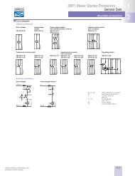
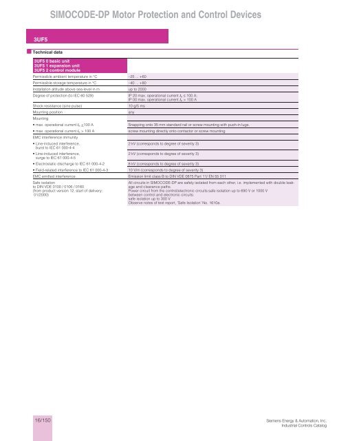
SIMOCODE-DP Motor Protection and Control Devices<br />
3UF5<br />
■ <strong>Technical</strong> data<br />
3UF5 0 basic unit<br />
3UF5 1 expansion unit<br />
3UF5 2 control module<br />
Permissible ambient temperature in °C –25 ... +60<br />
Permissible storage temperature in °C –40 ... +80<br />
Installation altitude above sea-level in m up to 2000<br />
Degree of protection (to IEC 60 529) IP 20 max. operational current I e ≤ 100 A;<br />
IP 00 max. operational current I e > 100 A<br />
Shock resistance (sine pulse)<br />
10 g/5 ms<br />
Mounting position<br />
any<br />
Mounting<br />
•max. operational current I e 100 A<br />
EMC interference immunity<br />
Snapping onto 35 mm standard rail or screw mounting with push-in lugs.<br />
screw mounting directly onto contactor or screw mounting<br />
•Line-induced interference,<br />
2 kV (corresponds to degree of severity 3)<br />
burst to IEC 61 000-4-4<br />
•Line-induced interference,<br />
2 kV (corresponds to degree of severity 3)<br />
surge to IEC 61 000-4-5<br />
•Electrostatic discharge to IEC 61 000-4-2 8 kV (corresponds to degree of severity 3)<br />
•Field-related interference to IEC 61 000-4-3 10 V/m (corresponds to degree of severity 3)<br />
EMC emitted interference Emission limit class B to DIN VDE 0875 Part 11/ EN 55 011<br />
Safe isolation<br />
to DIN VDE 0100 / 0106 / 0160<br />
(from product version 12, start of delivery:<br />
01/2000)<br />
All circuits in SIMOCODE-DP are safely isolated from each other, i.e. implemented with double leakage<br />
and clearance paths.<br />
Power circuit from the control/electronic circuits:safe isolation up to 690 V or 1000 V<br />
between control and electronic circuits:<br />
safe isolation up to 300 V<br />
Observe notes of test report, ’Safe Isolation’ No. 1610a.<br />
16/150<br />
<strong>Siemens</strong> Energy & Automation, Inc.<br />
Industrial Controls Catalog
SIMOCODE-DP Motor Protection and Control Devices<br />
3UF5<br />
■ <strong>Technical</strong> data<br />
3UF5 0 basic unit<br />
Displays<br />
•green LED "Ready"<br />
•green LED "Bus"<br />
•red LED "General Fault"<br />
ButtonsTest/Reset<br />
System interface<br />
PROFIBUS-DP interface<br />
Main circuit<br />
steady light: "Operational"<br />
Off: "No control supply voltage" or "Function test was negative; device is locked"<br />
steady light: "Bus operation"<br />
steady light/flashing light "Branch fault", e.g. overload tripping<br />
By pressing the Test/Reset button, the device can be reset following a trip or its functions can be<br />
tested<br />
RS 232 for connecting the expansion module, control module or PC<br />
RS 485 for connecting the PROFIBUS-DP line via terminals<br />
(conductor cross-sections as for auxiliary contacts) or 9-pole SUB D socket<br />
Insulation rating U i<br />
(at pollution degree 3) in V<br />
•for uninsulated conductors<br />
(3UF5 001 to 3UF5 021)<br />
•for insulated conductors<br />
(3UF5 001 to 3UF5 021)<br />
•for uninsulated and insulated conductors<br />
(3UF5 031 to 3UF5 051)<br />
Rated impulse withstand voltage U imp in kV<br />
690<br />
1000<br />
1000<br />
•3UF50001 to 3UF50 021 6<br />
•3UF5031 to 3UF5 051 8<br />
Rated frequency in Hz 50 / 60<br />
Type of current<br />
Three-phase<br />
Short-circuit protection See table Short-circuit protection with fuses for motor feeders ....<br />
Diameter of through-openings<br />
(max. I e = 100 A) in mm<br />
•Devices with max. operational current I e ≤ 25 A 10<br />
•Devices with max. operational current I e ≤ 100 A 15<br />
•Devices with max. operational current I e >100 A Construction with connecting bars<br />
Bar connection<br />
•Current range in A 50 ... 205 125 ... 500 200 ...820<br />
•Tightening torque in Nm M 8: 10 ... 14 M 10: 14 ... 24 M 10: 14 ... 24<br />
M 12: 20 ... 35<br />
•finely stranded cable lug in mm 2 35 ... 95 50 ... 240 50 ... 240<br />
•stranded with cable lug in mm 2 50 ... 120 70 ... 240 70 ... 240<br />
<strong>Siemens</strong> Energy & Automation, Inc.<br />
Industrial Controls Catalog<br />
16/151
SIMOCODE-DP Motor Protection and Control Devices<br />
3UF5<br />
■ <strong>Technical</strong> data<br />
Auxiliary circuit/control circuit<br />
Rated control supply voltage U s<br />
AC 50/60 Hz<br />
DC 24 V<br />
115 V and 230 V<br />
Operating range<br />
AC 50/60 Hz<br />
0.85 ... 1.1 × U s<br />
DC 24 V<br />
0.85 ... 1.2 × U s (DIN 19 240)<br />
Power consumption 50/60 Hz AC, 5 VA DC 24 V, 5 W<br />
Rated insulation voltage U i in V 300 (at pollution degree 3)<br />
Rated impulse withstand voltage U imp in kV 4<br />
Outputs<br />
•Number<br />
4 monostable/bistable outputs depending on the variant<br />
•Auxiliary contacts of the 4 outputs<br />
•Specified short-circuit protection for auxiliary contacts<br />
(outputs)<br />
Continuous rated current in A 5<br />
Rated operational current<br />
(switching capacity)<br />
Inputs<br />
Thermistor motor protection<br />
(PTC temperature sensor)<br />
•Total cold resistance in kΩ 1.5<br />
•Response threshold in kΩ 2.7 ... 3.1<br />
•Return value in kΩ 1.5 ... 1.65<br />
Conductor cross-sections<br />
•Tightening torque in Nm 0.8 ... 1.2<br />
•solid and stranded in mm 2 1 × (0.5 ... 4.0); 2 × (0.5 ... 2.5)<br />
•finely stranded with/without end sleeve in mm 2 1 × (0.5 ... 2.5); 2 × (0.5 ... 1.5)<br />
3UF5 1 expansion module<br />
16/152<br />
NC response can be parameterized by means of internal signal conditioning, whereby 3 outputs are<br />
connected to a common potential and 1 is connected to a separate potential; they can be freely<br />
assigned to the control functions (e.g. for activating the mains, star and delta contactors and sigalling<br />
the operational status)<br />
Fuse inserts for utilization category gL/gA 6A, quick 10 A; miniature circuit breaker 1.6 A, C characteristic<br />
AC-15; 6 A/24 V; 6 A/120 V; 3 A/230 V<br />
DC-13; 2 A/24 V; 0.55 A/60 V; 0.25 A/125 V<br />
4 inputs, supplied by the device electronics (DC 24 V), jointly connected to a common potential, for<br />
injecting process signals such as local control points, key-operated switches or limit switches<br />
System interface<br />
RS 232 as connection to the basic unit and for connecting the control module or PC<br />
Rated insulation voltage U i in V 300 (at pollution degree 3)<br />
Rated impulse withstand voltage U imp in kV 4<br />
Outputs<br />
•Number<br />
4 bistable outputs<br />
•Auxiliary contacts of the 4 outputs<br />
each with 1 floating NO contact, NC response can be parameterized by means of internal signal conditioning,<br />
whereby 3 outputs are connected to a common potential and 1 is connected to a separate<br />
potential; they can be freely assigned to the control functions (e.g. for activating the mains, star and<br />
delta contactors and sigalling the operational status)<br />
•Specified short-circuit protection for auxiliary contacts<br />
(outputs)<br />
Continuous rated current in A 5<br />
Rated operational current<br />
(switching capacity)<br />
Inputs<br />
Fuse links, utilisation category gL/gA 6 A, quick-acting 10 A;<br />
Circuit-breaker, 1.6 A, C characteristic<br />
AC-15; 6 A/24 V; 6 A/120 V; 3 A/230 V<br />
DC-13; 2 A/24 V; 0.55 A/60 V; 0.25 A/125 V<br />
8 externally supplied DC 24 V, AC 115 V, AC 230 V jointly connected to a common potential, for injecting<br />
process signals such as local control points, key-operated switches or limit switches<br />
Conductor cross-sections<br />
•Tightening torque in Nm 0.8 ... 1.2<br />
•solid and stranded in mm 2 1 × (0.5 ... 4.0); 2 × (0.5 ... 2.5)<br />
•finely stranded with/without end sleeve in mm 2 1 × (0.5 ... 2.5); 2 × (0.5 ... 1.5)<br />
3UF5 2 control module<br />
Displays<br />
•green LED "Ready"<br />
steady light: "Operational"<br />
Off: "No control supply voltage" or "Function test was negative; device is locked"<br />
•red LED "General Fault"<br />
steady light/flashing light "Branch fault", e.g. overload tripping<br />
•3 green and 3 yellow LEDs branch-specific displays, freely-assignable, e.g. manual/automatic mode, tripping of thermistor protection,<br />
clockwise/counterclockwise rotation etc.<br />
Buttons<br />
•Test/Reset<br />
By pressing the Test/Reset button, the device can be reset following a trip or its functions can be<br />
tested<br />
•Control keys<br />
For controlling the motor feeder, freely programmable.<br />
System interface<br />
RS 232 as connection to the basic unit or expansion module and for connection to a PC<br />
<strong>Siemens</strong> Energy & Automation, Inc.<br />
Industrial Controls Catalog
SIMOCODE-DP Motor Protection and Control Devices<br />
3UF5<br />
■ <strong>Technical</strong> data<br />
Short-circuit protection with fuses<br />
for motor feeders with short-circuit currents up to 50 kA at 690 V for 3RB1 2 and<br />
3UF5 0<br />
Overload<br />
relay<br />
Contactor CLASS Fuse links 3 )<br />
5 and 10 15 20 25 30 LV HRC Type 3NA LV HRC British<br />
Rated operational current I e AC-3 in A at ... V DIAZED Type 5SB Type 3ND Standard<br />
NEOZED Type 5SE aM fuses<br />
U L-listed<br />
fuses<br />
RK5<br />
Utilization<br />
category<br />
gL (gG)<br />
1) Mounting onto contactor is possible.<br />
2) Type of coordination and short-circuit protection devices according to IEC 947-4-1/DIN VDE 660 Part 102:<br />
•Type of coordination "1": In the event of a short-circuit, the contactor or starter must not endanger persons or the installation. They do not need to be suitable<br />
for further operation without repair and the renewal of parts.<br />
•Type of coordination "2": In the event of a short-circuit, the contactor or starter must not endanger persons or the installation. They must be suitable for further<br />
operation. There is a danger of contact welding.<br />
3) Observe operating voltage.<br />
4) Ensure that the maximum AC-3 operating current is sufficiently different from the rated fuse current.<br />
BS88<br />
Type T<br />
400 500 690 400 500 690 400 500 690 400 500 690 400 500 690 Type of coordination 2 )<br />
1 2 2 2 acc. to 2<br />
UL508<br />
Setting range 1.25 to 6.3 A<br />
3UF5 00 3RT1 015 6.3 5.0 4.0 6.3 5.0 4.0 6.3 5.0 4.0 6.3 5.0 4.0 6.3 5.0 4.0 35 20 20 25 –<br />
3RT1 016 6.3 6.3 5.2 6.3 6.3 5.2 6.3 6.3 5.2 6.3 6.3 5.2 6.3 6.3 5.2 35 20 20 25 –<br />
3RT1 017 6.3 6.3 6.3 6.3 6.3 6.3 6.3 6.3 6.3 6.3 6.3 6.3 6.3 6.3 6.3 35 20 20 25 –<br />
Setting range 6.3 to 25 A<br />
3UF5 01 3RT1 015 7.0 7.0 7.0 7.0 7.0 35 20 20 60 –<br />
3RT1 016 9.0 6.5 9.0 6.5 9.0 6.5 9.0 6.5 9.0 6.5 35 20 20 60 –<br />
3RT1 017 12.0 9.0 6.3 11.0 9.0 6.3 10.0 9.0 6.3 9.5 9.0 6.3 9.0 9.0 6.3 35 20 20 60 –<br />
3RT1 024 12.0 12.0 9.0 12.0 12.0 9.0 12.0 12.0 9.0 12.0 12.0 9.0 12.0 12.0 9.0 63 25 20 25 70 –<br />
3RT1 025 17.0 17.0 13.0 17.0 17.0 13.0 16.0 16.0 13.0 15.0 15.0 13.0 14.0 14.0 13.0 63 25 20 25 70 –<br />
3RT1 026 25.0 18.0 13.0 18.0 18.0 13.0 16.0 16.0 13.0 15.0 15.0 13.0 14.0 14.0 13.0 100 35 20 35 100 –<br />
3RT1 034 25.0 25.0 25.0 25.0 25.0 25.0 22.3 22.3 22.3 20.3 20.3 20.3 19.1 19.1 19.1 125 63 50 63 100 –<br />
3RT1 035 25.0 25.0 25.0 25.0 25.0 25.0 25.0 25.0 25.0 125 63 50 63 100 –<br />
Setting range 25 to 100 A<br />
3UF5 02 3RT1 034 32.0 32.0 25.5 25.5 125 63 50 63 125 –<br />
3RT1 035 40.0 40.0 33.0 33.0 29.4 29.4 28.0 28.0 26.5 26.5 125 63 50 63 150 –<br />
3RT1 036 50.0 50.0 38.5 38.5 32.7 32.7 29.4 29.4 26.5 26.5 160 80 50 80 200 –<br />
3RT1 044 65.0 65.0 47.0 56.0 56.0 47.0 49.0 49.0 47.0 45.0 45.0 45.0 41.7 41.7 41.7 250 125 63 125 250 –<br />
3RT1 045 80 80 58 61 61 58 53 53 58 47 47 47 45 45 45 250 160 80 160 250 –<br />
3RT1 046 95 95 58 69 69 58 59 59 58 53 53 53 50 50 50 250 160 100 160 350 –<br />
3RT1 054 115 115 115 93 93 93 82 82 82 75 75 75 69 69 69 355 315 160 160 – 175<br />
3RT1 055 150 150 150 122 122 122 107 107 107 98 98 98 90 90 90 355 315 200 200 – 200<br />
3RT1 056 185 185 170 150 150 150 131 131 131 120 120 120 111 111 111 355 315 200 250 – 200<br />
Setting range 50 to 205 A<br />
3UF5 03 3RT1 054 115 115 115 93 93 93 82 82 82 75 75 75 69 69 69 355 315 160 160 - 175<br />
3RT1 055 150 150 150 122 122 122 107 107 107 98 98 98 90 90 90 355 315 200 200 - 200<br />
3RT1 056 185 185 170 150 150 150 131 131 131 120 120 120 111 111 111 355 315 200 250 - 200<br />
3RT1 064 225 225 225 182 182 182 160 160 160 146 146 146 135 135 135 500 400 250 250 - 300<br />
3RT1 065 265 265 265 215 215 215 188 188 188 172 172 172 159 159 159 500 400 315 355 - 300<br />
3RT1 066 300 300 280 243 243 243 213 213 213 195 195 195 180 180 180 500 400 315 400 - 300<br />
3RT1 075 400 400 400 324 324 324 284 284 284 260 260 260 240 240 240 630 400 400 450 - 400<br />
3RT1 264 225 225 225 225 225 225 225 225 225 194 194 194 173 173 173 500 500 400<br />
3RT1 265 265 265 265 265 265 265 265 265 265 228 228 228 204 204 204 500 500 400<br />
3RT1 266 300 300 300 300 300 300 300 300 300 258 258 258 231 231 231 500 500 400<br />
3RT1 275 400 400 400 400 400 400 400 400 400 344 344 344 308 308 308 800 800 630<br />
Setting range 125 to 500 A<br />
3UF5 04 3RT1 056 185 185 170 150 150 150 131 131 131 120 120 120 111 111 111 355 315 200 250 – 200<br />
3RT1 064 225 225 225 182 182 182 160 160 160 146 146 146 135 135 135 500 400 250 315 – 300<br />
3RT1 065 265 265 265 215 215 215 188 188 188 172 172 172 159 159 159 500 400 315 355 – 300<br />
3RT1 066 300 300 280 243 243 243 213 213 213 195 195 195 180 180 180 500 400 315 400 – 300<br />
3RT1 075 400 400 400 324 324 324 284 284 284 260 260 260 240 240 240 630 500 500 500 – 400<br />
3RT1 076 500 500 450 405 405 405 355 355 355 325 325 325 300 300 300 630 630 630 630 – 400<br />
3RT1 264 225 225 225 225 225 225 225 225 225 194 194 194 173 173 173 500 500 400<br />
3RT1 265 265 265 265 265 265 265 265 265 265 228 228 228 204 204 204 500 500 400<br />
3RT1 266 300 300 300 300 300 300 300 300 300 258 258 258 231 231 231 500 500 400<br />
3RT1 275 400 400 400 400 400 400 400 400 400 344 344 344 308 308 308 800 800 630<br />
3RT1 276 500 500 500 500 500 500 500 500 500 430 430 430 385 385 385 800 800 630<br />
3TF6 8 500 500 500 500 500 500 440 440 440 408 408 408 376 376 376 800 500 4 ) 630 500 – 1200<br />
3TF6 9 500 500 500 500 500 500 500 500 500 800 630 4 ) 630 500 – CLASS L<br />
Setting range 200 to 820 A<br />
3UF5 05 3TF6 8 1 ) 630 630 630 502 502 502 440 440 440 408 408 408 376 376 376 1000 500 4 ) 630 500 – 1200<br />
3TF6 9 1 ) 820 820 820 662 662 662 572 572 572 531 531 531 500 500 500 1250 630 4 ) 630 630 – CLASS L<br />
<strong>Siemens</strong> Energy & Automation, Inc.<br />
Industrial Controls Catalog<br />
16/153