Solid-State Switching Devices for Resistive Loads - Siemens
Solid-State Switching Devices for Resistive Loads - Siemens
Solid-State Switching Devices for Resistive Loads - Siemens

Create successful ePaper yourself
Turn your PDF publications into a flip-book with our unique Google optimized e-Paper software.
SIRIUS<strong>Solid</strong>-<strong>State</strong> <strong>Switching</strong> <strong>Devices</strong>ContentsPagesIntroduction . . . . . . . . . . . . . . . . . . . . . . . . . . . . . . . . . . .7/2<strong>Solid</strong>-state switching devicesGeneral data . . . . . . . . . . . . . . . . . . . . . . . . . . . . . . . . . .7/3<strong>Solid</strong>-state switching devices <strong>for</strong> resistive loadsGeneral data . . . . . . . . . . . . . . . . . . . . . . . . . . . . . . . . . .7/5<strong>Solid</strong>-state relays3RF21 solid-state relays, single-phase, 22.5 mm . . . .7/83RF20 solid-state relays, single-phase, 45 mm . . . . . .7/93RF22 solid-state relays, three-phase, 45 mm . . . . .7/10<strong>Solid</strong>-state contactorsGeneral data . . . . . . . . . . . . . . . . . . . . . . . . . . . . . . .7/113RF23 solid-state contactors, single-phase . . . . . . . .7/123RF24 solid-state contactors, 3-phase . . . . . . . . . . . .7/14<strong>Solid</strong>-state switching devices <strong>for</strong> switching motors<strong>Solid</strong>-state contactorsGeneral data . . . . . . . . . . . . . . . . . . . . . . . . . . . . . . .7/153RF24 solid-state contactors, 3-phase . . . . . . . . . . . .7/163RF24 solid-state reversing contactors, 3-phase . . . .7/173RF29 Function modulesGeneral data . . . . . . . . . . . . . . . . . . . . . . . . . . . . . . .7/18Converters . . . . . . . . . . . . . . . . . . . . . . . . . . . . . . . . .7/23Load monitoring . . . . . . . . . . . . . . . . . . . . . . . . . . . . .7/24Heating current monitoring . . . . . . . . . . . . . . . . . . . .7/25Power controllers . . . . . . . . . . . . . . . . . . . . . . . . . . .7/26Power regulators . . . . . . . . . . . . . . . . . . . . . . . . . . . .7/27<strong>Solid</strong>-state switching devicesTechnical data <strong>for</strong> resistive loads<strong>Solid</strong>-state relaysGeneral data . . . . . . . . . . . . . . . . . . . . . . . . . . . . . . .7/293RF21 solid-state relays, single-phase, 22.5 mm . . .7/303RF20 solid-state relays, single-phase, 45 mm . . . . .7/333RF22 solid-state relays, three-phase, 45 mm . . . . .7/54<strong>Solid</strong>-state contactors3RF23 solid-state contactors, single-phase . . . . . . . .7/353RF29 Function modulesConverters, load monitors, power controller,heating current monitors . . . . . . . . . . . . . . . . . . . . . .7/41Power control regulators . . . . . . . . . . . . . . . . . . . . . .7/43Project planning aids . . . . . . . . . . . . . . . . . . . . . . . . .7/44Technical data <strong>for</strong> switching motors<strong>Solid</strong>-state contactors3RF24 solid-state contactors, three-phase . . . . . . . .7/563RF24 solid-state reversing contactors,three-phase . . . . . . . . . . . . . . . . . . . . . . . . . . . . . . . .7/61Project planning aids . . . . . . . . . . . . . . . . . . . . . . . . .7/64<strong>Siemens</strong> Industry, Inc.Industrial Controls Catalog7/1
<strong>Solid</strong>-<strong>State</strong> <strong>Switching</strong> <strong>Devices</strong>IntroductionOverview3RF213RF203RF223RF23SIRIUS solid-state switching devices <strong>for</strong> switching resistive loads<strong>Solid</strong>-state relays22.5 mm solid-state relays,45 mm solid-state relays<strong>Solid</strong>-state contactors<strong>Solid</strong>-state contactorsFunction modules• Widths of 22.5 mm and 45 mm• Compact and space-saving design• "Zero-point switching" version• Mounting onto existing heat sinks3RF24 (Motor)Nomenclature Guide3RF2 0 20 - 1 A A 0 2SIRIUS SC Type Rating Terminal Type <strong>Switching</strong> Control Phases Coil Type Power Voltage3RF24• Complete units comprising a solid-state relay and an optimized heat sink,"ready to use"• Compact and space-saving design• Versions <strong>for</strong> resistive loads "zero-point switching"and inductive loads "instantaneous switching"• Special versions "Low Noise" and "Short-Circuit Resistant"For extending the functionality of the 3RF21 solid-state relays and the 3RF23solid-state contactors <strong>for</strong> many different applications:Order No.3RF21,3RF203RF223RF233RF24Converters• For converting an analog input signal into an on/off ratio;3RF29 00-0EA18 7/13can also be used on 3RF22 and 3RF24 3-phase switching devicesLoad monitoring • For load monitoring of one or more loads (partial loads) 3RF29 20-0FA08,3RF29 .0-0GA..7/14Heating current monitoringPower control regulators• For load monitoring of one or more loads (partial loads);remote teach• For supplying the current by means of a solid-state switching device dependingon a setpoint value.There is a choice of full-wave control and generalized phase control.Power controllers• For supplying the current by means of a solid-state switching devicedepending on a setpoint value.Closed-loop control: Full-wave control or generalized phase controlSIRIUS solid-state switching devices <strong>for</strong> switching motors<strong>Solid</strong>-state contactors<strong>Solid</strong>-state contactors<strong>Solid</strong>-state reversing contactors• Complete "ready to use" units with an integrated insulated heatsink• Compact and space-saving design• Version <strong>for</strong> motors, "instantaneous switching"3RF29Page7/97/107/437/247/463RF29 ..-0JA.. 7/143RF29 ..-0KA. 7/143RF29 .0-0HA.. 7/157/8, 7/123RF24 7/467/470 = 45 mm Relay1 = 22.5 mm Relay2 = 3-phase 45 mm Relay3 = Contactor4 = 3-phase Contactor9 = Function Module1 = Screw2 = Spring3 = Ring ToungeA = Zero PointB = InstantaneousC = Low NoiseD = Short CircuitA = 1-phaseB = 2-phaseC = 3-phaseNote: This is only a guide to decode the model number. All possible combinations of these are not produced.0 = 24 VDC2 = 110 - 230 VAC4 = 4 - 30 VDC5 = 230 VAC2 = 24 - 230 VAC4 = 230 - 460 VAC5 = 48 - 600 VAC6 = 400 - 600 VAC7/2<strong>Siemens</strong> Industry, Inc.Industrial Controls Catalog
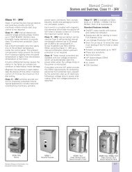
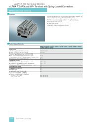
<strong>Solid</strong>-<strong>State</strong> <strong>Switching</strong> <strong>Devices</strong>General data<strong>Siemens</strong> Industry, Inc.Industrial Controls CatalogBenefits• Considerable space savings thanks to a width of only 22.5 mm• Variety of connection techniques: screw connection, springtypeconnection or ring terminal end, makes <strong>for</strong> easyterminations• Flexible <strong>for</strong> a wide range of applications with function modules<strong>for</strong> retrofitting• Possibility of fuseless short-circuit resistant designAdvantages:• Saves time and costs with easy wiring, simple installation andfast commissioning• Extremely long life, low maintenance, rugged and reliable• Space-saving and safe thanks to side-by-side mounting up toan ambient temperature of +60 °C• Modular design: standardized function modules and heat sinkscan be used in conjunction with 22.5 mm style semiconductorrelays to satisfy unique application requirements• Vibration-resistant and shock-resistant spring-loaded terminalconnection system provides a superior connection even undertough conditionsArea of applicationApplications<strong>Solid</strong>-state relaysSIRIUS solid-state relays are suitable <strong>for</strong> surface mounting onexisting cooling surfaces. Installation is quick and easy,involving just two screws. The special technology of the powersemiconductor ensures there is excellent thermal contact withthe heat sink. Depending on the nature of the heat sink, thecapacity reaches up to 88 A on resistive loads.The solid-state relays are available in three different versions:• 3RF21 single-phase solid-state relay with a width of 22.5 mm• 3RF20 single-phase solid-state relay with a width of 45 mm• 3RF22 three-phase solid-state relay with a width of 45 mmThe 3RF21 and 3RF22 solid-state relays can be expanded withvarious function modules to adapt them to individual applications.<strong>Solid</strong>-state contactorsThe complete units consist of a solid-state relay plus optimizedheat sink, and are there<strong>for</strong>e ready to use. They offer definedrated currents to make selection as easy as possible. Dependingon the version, current intensities of up to 88 A are achieved.Like all of our solid-state switching devices, one of their particularadvantages is their compact and space-saving design.With their insulated mounting foot they can easily be snappedonto a standard mounting rail, or they can be mounted on carrierplates with fixing screws. This insulation enables them to beused in circuits with protective extra-low voltage (PELV) or safetyextra-low voltage (SELV) in building engineering. For other applications,such as <strong>for</strong> extended personal safety, the heat sink canbe grounded through a screw terminal.The solid-state contactors are available in two different versions:• 3RF23 single-phase solid-state contactors• 3RF24 three-phase solid-state contactors3RF22 three-phase solid-state relay with a width of 45 mmWith its compact design, which stays the same even at currentsof up to 55 A, the 3RF22 solid-state relay is the ultimate in spacesavingconstruction, at a width of 45 mm. Installation on coolingsurfaces is quick and easy, involving just two screws. The logicalconnection arrangement, with the power infeed from above andconnection of the load from below, ensures tidy installation in thecontrol cabinet.3RF24 three-phase solid-state contactorsThe compact design enables small compact units with currentsup to 50 A. All special features of the solid-state relays <strong>for</strong> savingtime and space are effective here too.Example plastic machine industry:Thanks to their high switching endurance, SIRIUS SC semiconductorswitching devices are ideally suited <strong>for</strong> use in the controlof electroheat. This is because the more precise the temperatureregulation process has to be, the higher the switching frequencyneeds to be. The accurate regulation of electroheat is used <strong>for</strong>example in many processes in the plastic machine industry:• Band heaters heat the extrudate to the correct temperature inplastic extruders• Heat emitters heat plastic blanks to the correct temperature• Heat drums dry plastic granules• Heating channels keep molds at the correct temperature inorder to manufacture different plastic parts without defects.The powerful SIRIUS SC semiconductor relays and contactorscan be used to control several heating loads at the same time.By using a load monitoring module the individual partial loadscan easily be monitored, and in the event of a failure a signal isgenerated which can be sent to the controller.Protecting the semiconductor relays and semiconductor contactorswith 5 SY supplemental protectors.Short-circuit protection and line protection with 5 SY supplementalprotectors is easy to achieve with SIRIUS SC semiconductorrelays and semiconductor contactors in comparison withdesigning load feeders with fuses. A special version of thesemiconductor contactors can be protected against damage inthe case of a short-circuit with 5 SY supplementary protectorwith type B tripping characteristic. This allows the low-cost andsimple design of fuseless load feeders with full protection ofthe switching device.DesignThere is no typical design of a load feeder with semiconductorrelays or semiconductor contactors; instead, the great variety ofconnection systems and control voltages offers universalapplication opportunities. SIRIUS SC semiconductor relays andsemiconductor contactors can be installed in fuseless or fusedfeeders, as required.There are special versions with which it is even possible toachieve short-circuit strength in a fuseless design.Mounting regulations>20 (0,8)3RF24..>70 (2,75)>20 (0,8)>50 (2)Distances <strong>for</strong> stand-alone installation3RF24..>20 (0,8)NSB0_018147/5
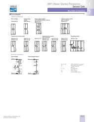
<strong>Solid</strong>-<strong>State</strong> <strong>Switching</strong> <strong>Devices</strong>General dataFunctionsConnectionAll SIRIUS SC semiconductor switching devices are characterizedby the great variety of connection methods. You canchoose between the following connection techniques:SIGUT connection system (screw)The SIGUT connection system is the standard among industrialswitching devices. Open terminals and a plus-minus screw arejust two features of this technology. Two conductors of up to6 mm² 1) can be connected in just one terminal. As a result,loads of up to 50 A can be connected.Spring-loaded connection systemThis innovative technology holds the conductor without screwconnection. This means that very high vibration resistance isachieved. Two conductors of up to 2.5 mm² 1) can be connectedto each terminal. As a result, loads of up to 20 A can be dealtwith.Ring terminal end connectionThe ring terminal end connection is equipped with an M5 screw.Ring terminal ends of up to 25 mm² can be connected. In thisway it is possible to connect conductors with up to 88 A safely.Additional finger safety can be provided with a special cover.<strong>Switching</strong> typesIn order to guarantee an optimized control method <strong>for</strong> differentloads, the functionality of our semiconductor switching devicescan be adapted accordingly.The "zero-point switching" method is ideal <strong>for</strong> resistive loads,i.e. where the power semiconductor is activated at zero voltage.For inductive loads, on the other hand, <strong>for</strong> example in the caseof valves, it is better to go with "instantaneous switching". Bydistributing the ON point over the entire sine curve of the mainsvoltage, disturbances are reduced to a minimum.A special “low noise” version is available due to a special control,this special version can be used in public networks up to16A without any additional measures such as interference suppressorfilters. As a result, it con<strong>for</strong>ms to limit value curve classB according to EN 60947-4-3 in terms of emitted interference.Per<strong>for</strong>mance characteristicsThe per<strong>for</strong>mance of the semiconductor switching devices aresubstantially determined by the type of power semiconductorsused and the internal design. In the case of the SIRIUS SC semiconductorcontactors and semiconductor relays, only thyristorsare used instead of less powerful Triacs.Two of the most important features of thyristors are the blockingvoltage and the maximum load integral:Blocking voltageThyristors with a high blocking voltage can also be operatedwithout difficulty in power systems with high interference voltages.Separate protective measures, such as a protective circuitwith a varistor, are not necessary in most cases.With SIRIUS SC, <strong>for</strong> example, thyristors with 800 V blocking voltageare fitted <strong>for</strong> operation in power systems up to 230 V. Thyristorswith up to 1600 V are used <strong>for</strong> power systems with highervoltages.Maximum load integralOne of the purposes of specifying the maximum load integral(I²t) is to determine the rating of the short-circuit protection. Onlya large power semiconductor with a correspondingly high I²tvalue can be given appropriate protection against destructionfrom a short-circuit by means of a protective device matched tothe application. However, SIRIUS SC is also characterized by theoptimum matching of the thyristors (I²t value) with the rated currents.The rated currents specified on the devices in con<strong>for</strong>mancewith EN 60947-4-3 were confirmed by extensive testing.FunctionTwo-phase controlled versionIn many three-phase applications there is no need of a threephasecontroller. <strong>Loads</strong> in a delta circuit or wye circuit, whichhave no connection to the neutral conductor, can be safelyswitched on and off using only two phases.Nevertheless, the 3RF22 and 3RF24 three-phase solid-stateswitching devices provide the possibility of connecting all threephases to the switching device, with the middle phase loopeddirectly through the device. Thanks to the lower power losscompared to a three-phase controlled device it is possible <strong>for</strong>the mounted accessories to be more compact.Three-phase controlled versionThis version is used in three-phase applications which have toswitch all phases on and off <strong>for</strong> system reasons or in the case ofloads in a wye circuit with connection to the neutral conductor.1) For mm 2 to AWG conversion see page 19/21 of Industrial Controls catalog.7/6<strong>Siemens</strong> Industry, Inc.Industrial Controls Catalog
<strong>Solid</strong>-<strong>State</strong> <strong>Switching</strong> <strong>Devices</strong>General dataSelection and ordering dataBlank labelsUnit labeling plates(1 frame = 20 units)DesignationLabeling area(W x H )mm x mmUnit labeling plates<strong>for</strong> "SIRIUS" 1) 10 x 7 Pastelturquoise20 x 7 PastelturquoiseLabels <strong>for</strong> sticking<strong>for</strong> "SIRIUS"19 x 6 Pastelturquoise19 x 6 Zincyellow1) Computer labeling system <strong>for</strong> individual inscription of unit labeling platesavailable from:murrplastik Systemtechnik GmbH (http://www.murrplastik.de).Color DT Order No. ListPrice $per PUPU(UNIT,SET, M)PS*Weightper PUapprox.kgD 3RT19 00-1SB10 100 816 units 0.110C 3RT19 00-1SB20 100 340 units 0.220D 3RT19 00-1SB60 100 3060 units 0.150C 3RT19 00-1SD60 100 3060 units 0.150IntegrationNotes on integration in the load feedersThe SIRIUS solid-state switching devices are very easy to integrateinto the load feeders thanks to their industrial connectionmethod and design.Particular attention must however be paid to the circumstancesof the installation and ambient conditions, as the per<strong>for</strong>mance ofthe solid-state switching devices is largely dependent on these.Depending on the version, certain restrictions must be observed.Detailed in<strong>for</strong>mation, <strong>for</strong> example in relation to solidstatecontactors about the minimum spacing and to solid-staterelays about the choice of heat sink, is given in the technicalspecifications (see Technical In<strong>for</strong>mation LV 1 T or our Mall) andthe product data sheets.Despite the rugged power semiconductors that are used, solidstateswitching devices respond more sensitively to shortcircuitsin the load feeder. Consequently, special precautionshave to be taken against destruction, depending on the type ofdesign.<strong>Siemens</strong> generally recommends using SITOR semiconductorprotection fuses. These fuses also provide protection againstdestruction in the event of a short-circuit even when the solidstatecontactors and solid-state relays are fully utilized.Alternatively, if there is lower loading, protection can also be providedby standard fuses or miniature circuit breakers. This protectionis achieved by overdimensioning the solid-state switchingdevices accordingly. The technical specifications and theproduct data sheets contain details both about the solid-statefuse protection itself and about use of the devices with conventionalprotection equipment.Semiconductor motor and reversing contactors can be easilycombined with the 3RV motor starter protectors and 3RB2 overloadrelay from the SIRIUS modular system. Thus, fuseless andfuse motor feeders can be designed easily and in a spacesavingmanner.The solid-state switching devices <strong>for</strong> resistive loads are suitable<strong>for</strong> interference-free operation in industrial networks without furthermeasures. If they are used in public networks, it may benecessary <strong>for</strong> conducted interference to be reduced by meansof filters. This does not include the special solid-state contactorsof type 3RF23..-.CA.. "Low Noise". These comply with the classB limit values up to a rated current of 16 A. If other versions areused, and at currents of over 16 A, standard filters can be usedin order to comply with the limit values. The decisive factorswhen it comes to selecting the filters are essentially the currentloading and the other parameters (operational voltage, designtype, etc.) in the load feeder.Suitable filters can be ordered from EPCOS AG.You can find more in<strong>for</strong>mation on the Internet at:http://www.epcos.com* You can order this quantity or a multiple thereof.<strong>Siemens</strong> Industry, Inc.Industrial Controls Catalog7/7
SIRIUS SC Semiconductor <strong>Switching</strong> <strong>Devices</strong>Semiconductor Relays22.5 mm semiconductor relayssingle phase selectionSelection and ordering dataType Maximum achievablepower <strong>for</strong> typecurrent1) current and U e =115 V 230 V 400 V3RF21 20-1AA02 3RF21 20-2AA02 3RF21 20-3AA02Screw connection 2)Spring-loaded connectionRing cable connection PS* Weight per3) PUapprox.ListPrice $A kW kW kW Order No. Order No. Order No.kgZero-point switching, rated operational voltage U e = 24 V to 230 V20 2.3 4.6 - 3RF21 20-1AA@2 3RF21 20-2AA@2 3RF21 20-3AA@2 1 unit 0.07530 3.5 6.9 - 3RF21 30-1AA@2 - - 1 unit 0.07550 5.8 11.5 - 3RF21 50-1AA@2 3RF21 50-2AA@2 3RF21 50-3AA@2 1 unit 0.07570 8.1 16.1 - 3RF21 70-1AA@2 - - 1 unit 0.07590 10.4 20.7 - 3RF21 90-1AA@2 3RF21 90-2AA@2 3RF21 90-3AA@2 1 unit 0.075Zero-point switching, rated operational voltage U e = 24 V to 230 V, control DC 4 ... 30 V20 2.3 4.6 - 3RF21 20-1AA42 3RF21 20-2AA42 - 1 unit 0.07530 3.5 6.9 - 3RF21 30-1AA42 - - 1 unit 0.075Zero-point switching, rated operational voltage U e = 48 V to 460 V20 - 4.6 8 3RF21 20-1AA@4 3RF21 20-2AA@4 3RF21 20-3AA@4 1 unit 0.07530 - 6.9 12 3RF21 30-1AA@4 - - 1 unit 0.07550 - 11.5 20 3RF21 50-1AA@4 3RF21 50-2AA@4 4 ) 3RF21 50-3AA@4 1 unit 0.07570 - 16.1 28 3RF21 70-1AA@4 - - 1 unit 0.07590 - 20.7 36 3RF21 90-1AA@4 3RF21 90-2AA@4 3RF21 90-3AA@4 1 unit 0.075Zero-point switching, rated operational voltage U e = 48 V to 600 V, control DC 4 ... 30 V20 - 4.6 8 3RF21 20-1AA45 3RF21 20-2AA45 - 1 unit 0.07530 - 6.9 12 3RF21 30-1AA45 - - 1 unit 0.07550 - 11.5 20 3RF21 50-1AA45 - - 1 unit 0.07570 - 16.1 28 3RF21 70-1AA45 - - 1 unit 0.07590 - 20.7 36 3RF21 90-1AA45 - 3RF21 90-3AA44 1 unit 0.075Zero-point switching, rated operational voltage U e = 48 V to 600 V, blocking voltage 1600 V30 - - 12 3RF21 30-1AA@6 - - 1 unit 0.07550 - - 20 3RF21 50-1AA@6 3RF21 50-2AA@6 3RF21 50-3AA@6 1 unit 0.07570 - - 28 3RF21 70-1AA@6 - - 1 unit 0.07590 - - 36 3RF21 90-1AA@6 3RF21 90-2AA@6 3RF21 90-3AA@6 1 unit 0.075Zero-point switching, rated operational voltage U e = 48 V to 600 V, control 24 V DC low power70 - - 28 3RF21 70-1AA05-0KN0 - - 1 unit 0.075Zero-point switching, rated operational voltage U e = 24 V to 230 V, control 110 V to 230 V50 - - - 3RF21 50-1BA22 - - 1 unit 0.075instantaneous switching, rated operational voltage U e = 48 V to 460 V, control 24 V DCacc. to EN 61131-220 - - - 3RF21 20-1BA04 - - 1 unit 0.07530 - - - 3RF21 30-1BA04 - - 1 unit 0.07550 - - - 3RF21 50-1BA04 - - 1 unit 0.07570 - - - 3RF21 70-1BA04 - - 1 unit 0.07590 - - - 3RF21 90-1BA04 - - 1 unit 0.075Zero-point switching, rated operational voltage U e = 48 V to 600 V, control 24 V DCacc. to EN 61131-2, blocking voltage 1600 V50 - - - 3RF21 50-1BA06 - - 1 unit 0.075Low noise 3 ) - zero-point switching, rated operational voltage U e = 48 V to 460 V, control 24 V DCacc. to EN 61131-270 - - - 3RF21 70-1CA04 - - 1 unit 0.075Order No. extension <strong>for</strong>rated control supply voltage U sDC 24 V acc. to EN 61131-2 000AC 110 V... 230 V 222Other rated control supply voltages on request.1) The type current provides in<strong>for</strong>mation about the per<strong>for</strong>mance of the semiconductorrelay. The actual permitted operational current I e can be smallerdepending on the connection method and cooling conditions.2) Please note that this version can only be used <strong>for</strong> a rated current of up to50 A and a conductor cross section of 10 mm 2 .3) Please note that this version can only be used <strong>for</strong> a rated current of up to20 A and a conductor cross section of 2.5 mm 2 . See page 19/21 of Industrialcontrols catalog <strong>for</strong> mm 2 to AWG conversion chart.4) 50 A version with 24 AC/DC control - 3RF21 50-2AA14.Note: See page 19/21 of Industrial Controls catalog <strong>for</strong> mm 2 to AWGconversion chart.7/8Product Category: SIRIUS SC<strong>Siemens</strong> Industry, Inc.Industrial Controls Catalog
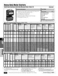
<strong>Solid</strong>-<strong>State</strong> <strong>Switching</strong> <strong>Devices</strong> <strong>for</strong> <strong>Resistive</strong> <strong>Loads</strong><strong>Solid</strong>-<strong>State</strong> ContactorsGeneral dataOverview<strong>Solid</strong>-state contactorsThe complete units consist of a solid-state relay plus optimizedheat sink, and are there<strong>for</strong>e ready to use. They offer definedrated currents to make selection as easy as possible. Dependingon the version, current strengths of up to 88 A are achieved.Like all of our solid-state switching devices, one of their particularadvantages is their compact and space-saving design.With their insulated mounting foot they can easily be snappedonto a standard mounting rail, or they can be mounted on supportplates with fixing screws. This insulation enables them to beused in circuits with protective extra-low voltage (PELV) or safetyextra-low voltage (SELV) in building management systems. Forother applications, such as <strong>for</strong> extended personal safety, theheat sink can be grounded through a screw terminal.The solid-state contactors are available in 2 different versions:• 3RF23 single-phase solid-state contactors,• 3RF24 three -phase solid-state contactorsSingle-phase versionsThe 3RF23 solid-state contactors can be expanded with variousfunction modules to adapt them to individual applications.Version <strong>for</strong> resistive loads, "zero-point switching"This standard version is often used <strong>for</strong> switching space heaterson and off.Version <strong>for</strong> inductive loads, "instantaneous switching"In this version the solid-state contactor is specifically matched toinductive loads. Whether it is a matter of frequent actuation of thevalves in a filling plant or starting and stopping small operatingmechanisms in packet distribution systems, operation is carriedout safely and noiselessly.Special "Low noise" versionThanks to a special control circuit, this special version can beused in public networks up to 16 A without any additional measuressuch as interference suppressor filters. As a result it con<strong>for</strong>msto limit value curve class B according to EN 60947-4-3 interms of emitted interference.Special "Short-circuit-proof" versionSkillful matching of the power semiconductor with the per<strong>for</strong>mancecapacity of the solid-state contactor means that "shortcircuitstrength" can be achieved with a standard miniature circuitbreaker. In combination with a B-type MCB or a conventionalline protection fuse, the result is a short-circuit resistantfeeder.In order to achieve problem-free short-circuit protection bymeans of miniature circuit breakers, however, certain boundaryconditions must be observed. As the magnitude and duration ofthe short-circuit current are determined not only by the short-circuitbreaking response of the miniature circuit breaker but alsothe properties of the wiring system, such as the internal resistanceof the input to the network and damping by controls andcables, particular attention must also be paid to these parameters.The necessary cable lengths are there<strong>for</strong>e shown <strong>for</strong> themain factor, the line resistance, in the table below.The following miniature circuit breakers with a type B trippingcharacteristic and 10 kA or 6 kA breaking capacity protect the3RF23..-.DA.. solid-state contactors in the event of short-circuitson the load and the specified conductor cross-sections andlengths:Rated current of theminiature circuitbreakerExampleType 1)6 A 5SY4 106-6,5SX2 106-610 A 5SY4 110-6,5SX2 110-616 A 5SY4 116-6,5SX2 116-616 A 5SY4 116-6,5SX2 116-620 A 5SY4 120-6,5SX2 120-625 A 5SY4 125-6,5SX2 125-6Max. conductorcross-section1 mm 2 5 m1.5 mm 2 8 m1.5 mm 2 12 m2.5 mm 2 20 m2.5 mm 2 20 m2.5 mm 2 26 mMinimum cablelength fromcontactor toload1) The miniature circuit breakers can be used up to a maximum rated voltageof 480 V!The setup and installation above can also be used <strong>for</strong> the solidstaterelays with a I 2 t value of at least 6600 A 2 s.Three-phase versionsThe three-phase solid-state contactors <strong>for</strong> resistive loads up to50 A are available with• two-phase control (suitable in particular <strong>for</strong> circuits withoutconnection to the neutral conductor) and• three-phase control (suitable <strong>for</strong> star circuits with connection tothe neutral conductor or <strong>for</strong> applications in which the systemrequires all phases to be switched).The converter function module can be snapped onto both versions<strong>for</strong> the simple power control of AC loads by means of analogsignals.• Check the correct contactor size with the aid of the rated currentdiagram, taking account of the design conditions.<strong>Siemens</strong> Industry, Inc.Industrial Controls Catalog7/11
SIRIUS SC Semiconductor <strong>Switching</strong> <strong>Devices</strong>Semiconductor ContactorsSIRIUS SC semiconductor contactorssingle phase selectionSelection and ordering dataSelecting solid-state contactorsThe semiconductor contactors are selected on the basis of detailsof the power system, the load and the ambient conditions.As the semiconductor contactors are already equipped with anoptimally matched heat sink, the selection process is considerablysimpler than that <strong>for</strong> semiconductor relays.The following procedure is recommended:• Determine the rated current of the load and the mains voltage• Select a semiconductor contactor with the same or higherrated current than the load• Check the correct contactor size with the aid of the rated currentdiagram, taking account of the design conditions3RF23 10-1AA02 3RF23 30-1AA02 3RF23 40-1AA02 3RF23 50-3AA02 3RF23 70-3AA02 3RF23 90-3AA02Type Maximum achievablepower <strong>for</strong>tionPU approx. Price $Screw connectionSpring-loaded connec-Ring cable connection PS* Weight per Listcurrent1)I max and U e =I max. 115 V 230 V 400 VA kW kW kW Order No. Order No. Order No.kgZero-point switching, rated operational voltage U e = 24 V to 230 V10.5 1.2 2.4 - 3RF23 10-1AA@2 3RF23 10-2AA@2 3RF23 10-3AA@2 1 unit 0.13620 2.3 4.6 - 3RF23 20-1AA@2 3RF23 20-2AA@2 3RF23 20-3AA@2 1 unit 0.20430 3.5 6.9 - 3RF23 30-1AA@2 - 3RF23 30-3AA@2 1 unit 0.35440 4.6 9.2 - 3RF23 40-1AA@2 - 3RF23 40-3AA@2 1 unit 0.49650 6 12 - 3RF23 50-1AA@2 - 3RF23 50-3AA@2 1 unit 0.49670 8 16 - - - 3RF23 70-3AA@2 1 unit 0.94488 10 20 - - - 3RF23 90-3AA@2 1 unit 2.600Zero-point switching, rated operational voltage U e = 24 V to 230 V, control 24 V DC acc. to EN 61131-2 3 )50 - - - 3RF20 50-4AA02 - - 1 unit 0.085Zero-point switching, rated operational voltage U e = 24 V to 230 V, control 24 V DC low power20 - - - 3RF23 20-1AA02-0KN0 - - 1 unit 0.240Zero-point switching, rated operational voltage U e = 48 V to 460 V10.5 - 2.4 4.2 3RF23 10-1AA@4 3RF23 10-2AA@4 3RF23 10-3AA@4 1 unit 0.13620 - 4.6 8 3RF23 20-1AA@4 3RF23 20-2AA@4 3RF23 20-3AA@4 1 unit 0.20430 - 6.9 12 3RF23 30-1AA@4 - 3RF23 30-3AA@4 1 unit 0.35440 - 9.2 16 3RF23 40-1AA@4 - 3RF23 40-3AA@4 1 unit 0.49650 - 12 20 3RF23 50-1AA@4 - 3RF23 50-3AA@4 1 unit 0.49670 - 16 28 - - 3RF23 70-3AA@4 1 unit 0.94488 - 20 35 - - 3RF23 90-3AA@4 1 unit 2.600Zero-point switching, rated operational voltage U e = 24 V to 230 V, control 24 V AC/DC10.5 - - - 3RF23 10-1AA12 - - 1 unit 0.165Zero-point switching, rated operational voltage U e = 48 V to 460 V, control 24 V DC low power50 - - - 3RF23 10-1AA04-0KN0 - - 1 unit 0.165Zero-point switching, rated operational voltage U e = 48 V to 460 V, control 24 V AC/DC10.5 - - - 3RF23 10-1AA14 - - 1 unit 0.16520 - - - 3RF23 20-1AA14 - - 1 unit 0.24030 - - - 3RF23 30-1AA14 - - 1 unit 0.40040 - - - 3RF23 40-1AA14 - - 1 unit 0.55050 - - - 3RF23 50-1AA14 - - 1 unit 0.550Zero-point switching, rated operational voltage U e = 48 V to 600 V, control DC 4 ... 30 V10.5 - 2.4 4.2 3RF23 10-1AA45 - - 1 unit 0.13520 - 4.6 8 3RF23 20-1AA45 - - 1 unit 0.20430 - 6.9 12 3RF23 30-1AA45 - - 1 unit 0.35440 - 9.2 16 3RF23 40-1AA45 - 3RF23 40-3AA45 1 unit 0.49650 - 12 20 3RF23 50-1AA45 - - 1 unit 0.49670 - 16 26 - - 3RF23 70-3AA45 1 unit 0.94490 - 20 35 - - 3RF23 90-3AA45 1 unit 2.600Zero-point switching, rated operational voltage U e = 48 V to 460 V, control 4 V ... 30 V DC10.5 - - - 3RF23 10-1AA44 - - 1 unit 0.16520 - - - 3RF23 20-1AA44 - 3RF23 20-3AA44 1 unit 0.24030 - - - 3RF23 30-1AA44 - 3RF23 30-3AA44 1 unit 0.40050 - - - 3RF23 50-1AA44 - 3RF23 50-3AA44 1 unit 0.400Zero-point switching, rated operational voltage U e = 48 V to 600 V, blocking voltage 1600 V10.5 - - 4.2 3RF23 10-1AA@6 3RF23 10-2AA@6 3RF23 10-3AA@6 1 unit 0.13620 - - 8 3RF23 20-1AA@6 3RF23 20-2AA@6 3RF23 20-3AA@6 1 unit 0.20430 - - 12 3RF23 30-1AA@6 - 3RF23 30-3AA@6 1 unit 0.35440 - - 16 3RF23 40-1AA@6 - 3RF23 40-3AA@6 1 unit 0.49650 - - 20 3RF23 50-1AA@6 - 3RF23 50-3AA@6 1 unit 0.49670 - - 28 - - 3RF23 70-3AA@6 1 unit 0.94488 - - 35 - - 3RF23 90-3AA@6 1 unit 2.600Order No. extension <strong>for</strong>rated control supply voltage U sDC 24 V acc. to EN 61131-2 000AC 110 V ... 230 V 222Other rated control supply voltages on request.1) The type current provides in<strong>for</strong>mation about the per<strong>for</strong>mance of the semiconductorcontactor. The actual permitted operational current I e can besmaller depending on the connection method and start-up conditions.Derating acc. to curves from page 7/45, 7/46, 7/47.7/12 Product Category: SIRIUS SC<strong>Siemens</strong> Industry, Inc.Industrial Controls Catalog
Other rated control supply voltages on request.1) The type current provides in<strong>for</strong>mation about the per<strong>for</strong>mance of the semiconductorcontactor. The actual permitted operational current I e can besmaller depending on the connection method and start-up conditions.Derating acc. to curves from page 7/45, 7/46, 7/47.SIRIUS SC Semiconductor <strong>Switching</strong> <strong>Devices</strong>Semiconductor ContactorsType Maximum achievablepower <strong>for</strong>tionPU approx. Price $Screw connectionSpring-loaded connec-Ring cable connection PS* Weight per Listcurrent1) I max and U e =I max. 115 V 230 V 400 VA kW kW kW Order No. Order No. Order No.kgInstantaneous switching, rated operational voltage U e = 24 V to 230 V10.5 1.2 2.4 - 3RF23 10-1BA@2 - - 1 unit 0.13620 2.3 4.6 - 3RF23 20-1BA@2 - - 1 unit 0.20430 3.5 6.9 - 3RF23 30-1BA@2 - - 1 unit 0.35440 4.6 9.2 - 3RF23 40-1BA@2 - - 1 unit 0.49650 6 12 - 3RF23 50-1BA@2 - - 1 unit 0.49670 8 16 - 3RF23 70-1BA@2 - 3RF23 70-3BA@2 1 unit 0.94488 10 20 - 3RF23 90-1BA@2 - 3RF23 90-3BA@2 1 unit 2.600Instantaneous switching, rated operational voltage U e = 48 V to 460 V10.5 - 2.4 4.2 3RF23 10-1BA@4 - - 1 unit 0.13620 - 4.6 8 3RF23 20-1BA@4 - - 1 unit 0.20430 - 6.9 12 3RF23 30-1BA@4 - - 1 unit 0.35440 - 9.2 16 3RF23 40-1BA@4 - - 1 unit 0.49650 - 12 20 3RF23 50-1BA@4 - - 1 unit 0.49670 - 16 28 3RF23 70-1BA@4 - 3RF23 70-3BA@4 1 unit 0.94488 - 20 35 3RF23 90-1BA@4 - 3RF23 90-3BA@4 1 unit 2.600Zero-point switching, rated operational voltage U e = 48 V to 600 V, control 110 V to 230 V30 - - - 3RF23 30-1AA25 - - 1 unit 0.400Instantaneous switching, rated operational voltage U e = 48 V to 600 V, blocking voltage 1600 V10.5 - - 4.2 3RF23 10-1BA@6 - - 1 unit 0.13620 - - 8 3RF23 20-1BA@6 - - 1 unit 0.20430 - - 12 3RF23 30-1BA@6 - - 1 unit 0.35440 - - 16 3RF23 40-1BA@6 - - 1 unit 0.49650 - - 20 3RF23 50-1BA@6 - - 1 unit 0.49670 - - 28 3RF23 70-1BA@6 - 3RF23 70-3BA@6 1 unit 0.94488 - - 35 3RF23 90-1BA@6 - 3RF23 90-3BA@6 1 unit 2.600Low noise, zero-point switching, rated operational voltage U e = 24 V to 230 V20 2.3 4.6 - 3RF23 20-1CA@2 3RF23 20-2CA@2 - 1 unit 0.20430 - - - 3RF23 30-1CA@2 - - 1 unit 0.204Low noise, zero-point switching, rated operational voltage U e = 48 V to 460 V20 - 4.6 8 3RF23 20-1CA@4 3RF23 20-2CA@4 - 1 unit 0.204Instantaneous switching, rated operational voltage U e = 48 V to 460 V,control DC 4 ... 30 V switching20 - - - 3RF23 20-1BA44 - - 1 unit 0.24030 - - - 3RF23 30-1BA44 - - 1 unit 0.40050 - - - 3RF23 50-1BA44 - - 1 unit 0.550Short-circuit resistant with B-automatic device, zero-point switching,rated operational voltage U e = 24 V to 230 V20 2.3 4.6 - 3RF23 20-1DA@2 3RF23 20-2DA22 3RF23 20-3DA@2 1 unit 0.204Short-circuit resistant with B-automatic device, zero-point switching,rated operational voltage U e = 48 V to 460 V20 - 4.6 8 3RF23 20-1DA@4 3RF23 20-2DA24 3RF23 20-3DA@4 1 unit 0.204Low noise, zero-point switching, rated operational voltage U e = 48 V to 460 V,control 4 V to 30 V DC70 - - 28 3RF21 70-1CA04 - - 1 unit 0.240Order No. extension <strong>for</strong>rated control supply voltage U sDC 24 V acc. to EN 61131-2 000AC 110 V ... 230 V 222Version Order No. StandardPackageQuantityAccessoriesTerminal cover <strong>for</strong> 3RF21 semiconductor relays and 3RF23 semiconductor contactorswith ring terminal end (after simple adaptation, this terminal cover can also be used <strong>for</strong>screw connection).SIRIUS SC semiconductor contactorssingle phase selectionWeightper PUapprox.kg3RF29 00-3PA88 10 units 0.010ListPrice $3RF29 00-3PA88<strong>Siemens</strong> Industry, Inc.Industrial Controls CatalogProduct Category: SIRIUS SC7/13
<strong>Solid</strong>-<strong>State</strong> <strong>Switching</strong> <strong>Devices</strong> <strong>for</strong> <strong>Resistive</strong> <strong>Loads</strong><strong>Solid</strong>-<strong>State</strong> Contactors3RF24 solid-state contactors, 3-phaseSelection and ordering dataType current 1)I maxA1) The type current provides in<strong>for</strong>mation about the per<strong>for</strong>mance capacity ofthe solid-state contactor. The actual permitted rated operational current I ecan be smaller depending on the connection method and start-upconditions. For derating, see Technical In<strong>for</strong>mation on page 7/55, CharacteristicCurves.Rated controlsupply voltage U sDT Screw terminals PS* Weightper PUapprox.Order No.ListVPrice $per PUkgZero-point switchingRated operational voltage U e 48 V ... 600 VTwo-phase controlled10.5 4 ... 30 DC A 3RF24 10-1AB45 1 unit 0.32020B 3RF24 20-1AB45 1 unit 0.40030B 3RF24 30-1AB45 1 unit 0.54040B 3RF24 40-1AB45 1 unit 0.80050B 3RF24 50-1AB45 1 unit 1.10010.5 110 AC A 3RF24 10-1AB35 1 unit 0.32020B 3RF24 20-1AB35 1 unit 0.40030B 3RF24 30-1AB35 1 unit 0.54040B 3RF24 40-1AB35 1 unit 0.8003RF24 20-1AB4550B 3RF24 50-1AB35 1 unit 1.10010.5 230 AC B 3RF24 10-1AB55 1 unit 0.32020B 3RF24 20-1AB55 1 unit 0.40030B 3RF24 30-1AB55 1 unit 0.54040B 3RF24 40-1AB55 1 unit 0.80050B 3RF24 50-1AB55 1 unit 1.100Three-phase controlled10.5 4 ... 30 DC B 3RF24 10-1AC45 1 unit 0.32020B 3RF24 20-1AC45 1 unit 0.54030A 3RF24 30-1AC45 1 unit 0.80040B 3RF24 40-1AC45 1 unit 1.10050B 3RF24 50-1AC45 1 unit 1.85010.5 110 AC B 3RF24 10-1AC35 1 unit 0.32020B 3RF24 20-1AC35 1 unit 0.54030A 3RF24 30-1AC35 1 unit 0.80040B 3RF24 40-1AC35 1 unit 1.1003RF24 10-1AC4550B 3RF24 50-1AC35 1 unit 1.85010.5 230 AC B 3RF24 10-1AC55 1 unit 0.32020B 3RF24 20-1AC55 1 unit 0.54030B 3RF24 30-1AC55 1 unit 0.80040B 3RF24 40-1AC55 1 unit 1.10050B 3RF24 50-1AC55 1 unit 1.850* You can order this quantity or a multiple thereof.7/14 <strong>Siemens</strong> Industry, Inc.Industrial Controls Catalog
<strong>Solid</strong>-<strong>State</strong> <strong>Switching</strong> <strong>Devices</strong> <strong>for</strong> <strong>Switching</strong> Motors<strong>Solid</strong>-<strong>State</strong> Contactors3RF24 solid-state contactors, 3-phaseOverviewThese two-phase controlled, instantaneous switching solid-statecontactors in the insulting enclosure are offered in 45 mm widthto 5.2 A – and in 90 mm width to 16 A. This means that it is possibleto operate motors up to 7.5 kW.The devices can use a link module 1) to directly connect to a circuitbreaker. Direct mounting on a 3RB20 electronic overloadrelay 2) is possible. Rapid-switching fuseless and fuse motorfeeders can thereby be implemented in a time-saving manner.Selection and ordering dataMotor contactors · Instantaneous switching · Two-phase controlledRatedoperationalcurrent I eRated powerat I e and U eRated controlsupply voltage U sDT Screw terminals PS* Weightper PUapprox.400 V Order No. ListA kW V Price $kgper PURated operational voltage U e 48 ... 460 V5.2 2.2 24 DC acc. to B 3RF24 05-1BB04 1 unit 0.2509.2 4.0 EN 61131-2 B 3RF24 10-1BB04 1 unit 0.38012.5 5.5 B 3RF24 12-1BB04 1 unit 0.38016 7.5 B 3RF24 16-1BB04 1 unit 0.3805.2 2.2 110 ... 230 AC B 3RF24 05-1BB24 1 unit 0.2509.2 4.0 B 3RF24 10-1BB24 1 unit 0.38012.5 5.5 B 3RF24 12-1BB24 1 unit 0.38016 7.5 B 3RF24 16-1BB24 1 unit 0.3803RF24 05-1BBRated operational voltage U e 48 ... 600 VBlocking voltage 1600 V5.2 2.2 24 DC acc. to B 3RF24 05-1BB06 1 unit 0.2509.2 4.0 EN 61131-2 B 3RF24 10-1BB06 1 unit 0.38012.5 5.5 B 3RF24 12-1BB06 1 unit 0.38016 7.5 B 3RF24 16-1BB06 1 unit 0.3805.2 2.2 110 ... 230 AC B 3RF24 05-1BB26 1 unit 0.2509.2 4.0 B 3RF24 10-1BB26 1 unit 0.38012.5 5.5 B 3RF24 12-1BB26 1 unit 0.38016 7.5 B 3RF24 16-1BB26 1 unit 0.3803RF24 10-1BBRatedoperationalcurrent I eRated powerat I e and U eRated controlsupply voltage U sDT Spring-loadedterminals400 V Order No. ListA kW V Price $kgper PURated operational voltage U e 48 ... 460 V5.2 2.2 24 DC acc. to B 3RF24 05-2BB04 1 unit 0.2509.2 4.0 EN 61131-2 B 3RF24 10-2BB04 1 unit 0.38012.5 5.5 B 3RF24 12-2BB04 1 unit 0.38016 7.5 B 3RF24 16-2BB04 1 unit 0.3805.2 2.2 110 ... 230 AC B 3RF24 05-2BB24 1 unit 0.2509.2 4.0 B 3RF24 10-2BB24 1 unit 0.38012.5 5.5 B 3RF24 12-2BB24 1 unit 0.38016 7.5 B 3RF24 16-2BB24 1 unit 0.3803RF24 10-2BBRated operational voltage U e 48 ... 600 VBlocking voltage 1600 V5.2 2.2 24 DC acc. to B 3RF24 05-2BB06 1 unit 0.2509.2 4.0 EN 61131-2 B 3RF24 10-2BB06 1 unit 0.38012.5 5.5 B 3RF24 12-2BB06 1 unit 0.38016 7.5 B 3RF24 16-2BB06 1 unit 0.3805.2 2.2 110 ... 230 AC B 3RF24 05-2BB26 1 unit 0.2509.2 4.0 B 3RF24 10-2BB26 1 unit 0.38012.5 5.5 B 3RF24 12-2BB26 1 unit 0.38016 7.5 B 3RF24 16-2BB26 1 unit 0.3801) For 3RA19 21-1AA00 link modules see Section 1,page 1/12.2) For 3RB20 overload relays see Section 3, page 3/23.PS*Weightper PUapprox.* You can order this quantity or a multiple thereof.7/16 <strong>Siemens</strong> Industry, Inc.Industrial Controls Catalog
<strong>Solid</strong>-<strong>State</strong> <strong>Switching</strong> <strong>Devices</strong> <strong>for</strong> <strong>Switching</strong> Motors<strong>Solid</strong>-<strong>State</strong> Contactors3RF24 solid-statereversing contactors, 3-phaseOverviewThe integration of four conducting paths to a reverse switch,combined in one enclosure makes this device a particularlycompact solution. Compared to conventional systems, <strong>for</strong> whichtwo contactors are required, it is possible to save up to 50 %width with the three-phase reversing contactors. <strong>Devices</strong> with45 mm width cover motors up to 2.2 kW – and those with 90 mmwidth up to 3 kW.Due to the integration into the SIRIUS modular system, it is possibleto make a connection to a SIRIUS motor starter protectorusing a link module 1) or with a 3RB20 solid-state overload relay 2)without additional steps. It is possible to mount fuseless or fusedmotor feeders easily and quickly.Selection and ordering dataReversing contactors · Instantaneous switching · Two-phase controlledRatedoperationalcurrent I eRated powerat I e and U eRated controlsupply voltage U sDT Screw terminals PS* Weightper PUapprox.400 V Order No. ListA kW V Price $kgper PURated operational voltage U e 48 ... 460 V3.8 1.5 24 DC acc. to B 3RF24 03-1BD04 1 unit 0.2805.4 2.2 EN 61131-2 B 3RF24 05-1BD04 1 unit 0.2807.4 3.0 B 3RF24 10-1BD04 1 unit 0.4103.8 1.5 110 ... 230 AC B 3RF24 03-1BD24 1 unit 0.2805.4 2.2 B 3RF24 05-1BD24 1 unit 0.2807.4 3.0 B 3RF24 10-1BD24 1 unit 0.4103RF24 03-1BD3RF24 10-1BD1) For 3RA19 21-1AA00 link modules see Section 1,page 1/12.2) For 3RB20 overload relays see Section 3, page 3/23.* You can order this quantity or a multiple thereof.<strong>Siemens</strong> Industry, Inc.Industrial Controls Catalog7/17
<strong>Solid</strong>-<strong>State</strong> <strong>Switching</strong> <strong>Devices</strong> <strong>for</strong> <strong>Resistive</strong> <strong>Loads</strong>3RF29 Function ModulesGeneral dataOverviewFunction modules <strong>for</strong> SIRIUS 3RF2 solid-state switching devicesA great variety of applications demand an expanded range offunctionality. With our function modules, these requirements canbe met really easily. The modules are mounted simply by clickingthem into place; straight away the necessary connectionsare made with the solid-state relay or contactor. The plug-in connectionto control the solid-state switching devices can simplyremain in use.The following function modules are available:•Converters• Load monitoring• Heating current monitoring• Power controllers• Power regulatorsWith the exception of the converter, the function modules can beused only with single-phase solid-state switching devices.Recommended assignment of the function modules to the 3RF21 single-phase solid-state relaysOrder No. AccessoriesConverters Load monitoring Heating current Power controllers 1) Power regulators 1)BasicExtendedmonitoringType current = 20 A3RF21 20-1A.02 3RF29 00-0EA18 3RF29 20-0FA08 3RF29 20-0GA13 -- 3RF29 20-0KA13 3RF29 20-0HA133RF21 20-1A.04 3RF29 00-0EA18 3RF29 20-0FA08 3RF29 20-0GA16 3RF29 32-0JA16 3RF29 20-0KA16 3RF29 20-0HA163RF21 20-1A.22 -- -- 3RF29 20-0GA33 -- -- --3RF21 20-1A.24 -- -- 3RF29 20-0GA36 -- -- --3RF21 20-1A.42 3RF29 00-0EA18 3RF29 20-0FA08 3RF29 20-0GA13 -- 3RF29 20-0KA13 3RF29 20-0HA133RF21 20-1A.45 3RF29 00-0EA18 3RF29 20-0FA08 3RF29 20-0GA16 3RF29 32-0JA16 3RF29 20-0KA16 3RF29 20-0HA163RF21 20-1B.04 3RF29 00-0EA18 3RF29 20-0FA08 3RF29 20-0GA16 3RF29 32-0JA16 3RF29 20-0KA16 3RF29 20-0HA163RF21 20-2A.02 3RF29 00-0EA18 -- -- -- -- --3RF21 20-2A.04 3RF29 00-0EA18 -- -- -- -- --3RF21 20-2A.22 -- -- -- -- -- --3RF21 20-2A.24 -- -- -- -- -- --3RF21 20-2A.42 3RF29 00-0EA18 -- -- -- -- --3RF21 20-2A.45 3RF29 00-0EA18 -- -- -- -- --3RF21 20-3A.02 3RF29 00-0EA18 -- 3RF29 20-0GA13 -- -- 3RF29 20-0HA133RF21 20-3A.04 3RF29 00-0EA18 -- 3RF29 20-0GA16 3RF29 32-0JA16 3RF29 20-0KA16 3RF29 20-0HA163RF21 20-3A.22 -- -- 3RF29 20-0GA33 -- 3RF29 20-0KA13 3RF29 20-0HA133RF21 20-3A.24 -- -- 3RF29 20-0GA36 -- 3RF29 20-0KA16 3RF29 20-0HA16Type current = 30 A3RF21 30-1A.02 3RF29 00-0EA18 3RF29 20-0FA08 3RF29 50-0GA13 -- -- 3RF29 50-0HA133RF21 30-1A.04 3RF29 00-0EA18 3RF29 20-0FA08 3RF29 50-0GA16 3RF29 32-0JA16 3RF29 50-0KA16 3RF29 50-0HA163RF21 30-1A.06 3RF29 00-0EA18 3RF29 20-0FA08 3RF29 50-0GA16 3RF29 32-0JA16 3RF29 50-0KA16 3RF29 50-0HA163RF21 30-1A.22 -- -- 3RF29 50-0GA33 -- -- 3RF29 50-0HA333RF21 30-1A.24 -- -- 3RF29 50-0GA36 -- -- 3RF29 50-0HA363RF21 30-1A.26 -- -- 3RF29 50-0GA36 -- -- 3RF29 50-0HA363RF21 30-1A.42 3RF29 00-0EA18 3RF29 20-0FA08 3RF29 50-0GA13 -- -- 3RF29 50-0HA133RF21 30-1A.45 3RF29 00-0EA18 3RF29 20-0FA08 3RF29 50-0GA16 3RF29 32-0JA16 3RF29 50-0KA16 3RF29 50-0HA163RF21 30-1B.04 3RF29 00-0EA18 3RF29 20-0FA08 3RF29 50-0GA16 3RF29 32-0JA16 3RF29 50-0KA16 3RF29 50-0HA16Type current = 50 A3RF21 50-1A.02 3RF29 00-0EA18 3RF29 20-0FA08 3RF29 50-0GA13 -- -- 3RF29 50-0HA133RF21 50-1A.04 3RF29 00-0EA18 3RF29 20-0FA08 3RF29 50-0GA16 3RF29 32-0JA16 3RF29 50-0KA16 3RF29 50-0HA163RF21 50-1A.06 3RF29 00-0EA18 3RF29 20-0FA08 3RF29 50-0GA16 3RF29 32-0JA16 3RF29 50-0KA16 3RF29 50-0HA163RF21 50-1A.22 -- -- 3RF29 50-0GA33 -- -- 3RF29 50-0HA333RF21 50-1A.24 -- -- 3RF29 50-0GA36 -- -- 3RF29 50-0HA363RF21 50-1A.26 -- -- 3RF29 50-0GA36 -- -- 3RF29 50-0HA363RF21 50-1A.45 3RF29 00-0EA18 3RF29 20-0FA08 3RF29 50-0GA16 3RF29 32-0JA16 3RF29 50-0KA16 3RF29 50-0HA163RF21 50-1B.04 3RF29 00-0EA18 3RF29 20-0FA08 3RF29 50-0GA16 3RF29 32-0JA16 3RF29 50-0KA16 3RF29 50-0HA163RF21 50-1B.06 3RF29 00-0EA18 3RF29 20-0FA08 3RF29 50-0GA16 3RF29 32-0JA16 3RF29 50-0KA16 3RF29 50-0HA163RF21 50-1B.22 -- -- 3RF29 50-0GA33 -- -- 3RF29 50-0HA333RF21 50-2A.02 3RF29 00-0EA18 -- -- -- -- --3RF21 50-2A.04 3RF29 00-0EA18 -- -- -- -- --3RF21 50-2A.06 3RF29 00-0EA18 -- -- -- -- --3RF21 50-2A.14 3RF29 00-0EA18 -- -- -- -- --3RF21 50-2A.22 -- -- -- -- -- --3RF21 50-2A.24 -- -- -- -- -- --3RF21 50-2A.26 -- -- -- -- -- --3RF21 50-3A.02 3RF29 00-0EA18 -- 3RF29 50-0GA13 -- -- 3RF29 50-0HA133RF21 50-3A.04 3RF29 00-0EA18 -- 3RF29 50-0GA16 3RF29 32-0JA16 3RF29 50-0KA16 3RF29 50-0HA163RF21 50-3A.06 3RF29 00-0EA18 -- 3RF29 50-0GA16 3RF29 32-0JA16 3RF29 50-0KA16 3RF29 50-0HA163RF21 50-3A.22 -- -- 3RF29 50-0GA33 -- -- 3RF29 50-0HA333RF21 50-3A.24 -- -- 3RF29 50-0GA36 -- -- 3RF29 50-0HA363RF21 50-3A.26 -- -- 3RF29 50-0GA36 -- -- 3RF29 50-0HA361) The use of power controllers/regulators is also possible on zero-pointswitching versions <strong>for</strong> full-wave control mode. The generalized phase controlmode is recommended only <strong>for</strong> the combination with instantaneousswitching versions.7/18 <strong>Siemens</strong> Industry, Inc.Industrial Controls Catalog
Order No.Accessories<strong>Solid</strong>-<strong>State</strong> <strong>Switching</strong> <strong>Devices</strong> <strong>for</strong> <strong>Resistive</strong> <strong>Loads</strong>3RF29 Function ModulesConverters Load monitoring Heating current Power controllers 1) Power regulators 1)BasicExtendedmonitoringType current = 70 A3RF21 70-1A.02 3RF29 00-0EA18 3RF29 20-0FA08 3RF29 50-0GA13 -- -- 3RF29 50-0HA133RF21 70-1A.04 3RF29 00-0EA18 3RF29 20-0FA08 3RF29 50-0GA16 3RF29 32-0JA16 3RF29 50-0KA16 3RF29 50-0HA163RF21 70-1A.05 3RF29 00-0EA18 3RF29 20-0FA08 3RF29 50-0GA16 3RF29 32-0JA16 3RF29 50-0KA16 3RF29 50-0HA163RF21 70-1A.06 3RF29 00-0EA18 3RF29 20-0FA08 3RF29 50-0GA16 3RF29 32-0JA16 3RF29 50-0KA16 3RF29 50-0HA163RF21 70-1A.22 -- -- 3RF29 50-0GA33 -- -- 3RF29 50-0HA333RF21 70-1A.24 -- -- 3RF29 50-0GA36 -- -- 3RF29 50-0HA363RF21 70-1A.26 -- -- 3RF29 50-0GA36 -- -- 3RF29 50-0HA363RF21 70-1A.45 3RF29 00-0EA18 3RF29 20-0FA08 3RF29 50-0GA16 3RF29 32-0JA16 3RF29 50-0KA16 3RF29 50-0HA163RF21 70-1B.04 3RF29 00-0EA18 3RF29 20-0FA08 3RF29 50-0GA16 3RF29 32-0JA16 3RF29 50-0KA16 3RF29 50-0HA163RF21 70-1C.04 3RF29 00-0EA18 3RF29 20-0FA08 3RF29 50-0GA16 3RF29 32-0JA16 3RF29 50-0KA16 3RF29 50-0HA16Type current = 90 A3RF21 90-1A.02 3RF29 00-0EA18 3RF29 20-0FA08 3RF29 50-0GA13 -- -- 3RF29 50-0HA133RF21 90-1A.04 3RF29 00-0EA18 3RF29 20-0FA08 3RF29 50-0GA16 3RF29 32-0JA16 3RF29 50-0KA16 3RF29 50-0HA163RF21 90-1A.06 3RF29 00-0EA18 3RF29 20-0FA08 3RF29 50-0GA16 3RF29 32-0JA16 3RF29 50-0KA16 3RF29 50-0HA163RF21 90-1A.22 -- -- 3RF29 50-0GA33 -- -- 3RF29 50-0HA333RF21 90-1A.24 -- -- 3RF29 50-0GA36 -- -- 3RF29 50-0HA363RF21 90-1A.26 -- -- 3RF29 50-0GA36 -- -- 3RF29 50-0HA363RF21 90-1A.45 3RF29 00-0EA18 3RF29 20-0FA08 3RF29 50-0GA16 3RF29 32-0JA16 3RF29 50-0KA16 3RF29 50-0HA163RF21 90-1B.04 3RF29 00-0EA18 3RF29 20-0FA08 3RF29 50-0GA16 3RF29 32-0JA16 3RF29 50-0KA16 3RF29 50-0HA163RF21 90-2A.02 3RF29 00-0EA18 -- -- -- -- --3RF21 90-2A.04 3RF29 00-0EA18 -- -- -- -- --3RF21 90-2A.06 3RF29 00-0EA18 -- -- -- -- --3RF21 90-2A.22 -- -- -- -- -- --3RF21 90-2A.24 -- -- -- -- -- --3RF21 90-2A.26 -- -- -- -- -- --3RF21 90-3A.02 3RF29 00-0EA18 -- 3RF29 90-0GA13 -- -- 3RF29 90-0HA133RF21 90-3A.04 3RF29 00-0EA18 -- 3RF29 90-0GA16 3RF29 32-0JA16 3RF29 90-0KA16 3RF29 90-0HA163RF21 90-3A.06 3RF29 00-0EA18 -- 3RF29 90-0GA16 3RF29 32-0JA16 3RF29 90-0KA16 3RF29 90-0HA163RF21 90-3A.22 -- -- 3RF29 90-0GA33 -- -- 3RF29 90-0HA333RF21 90-3A.24 -- -- 3RF29 90-0GA36 -- -- 3RF29 90-0HA363RF21 90-3A.26 -- -- 3RF29 90-0GA36 -- -- 3RF29 90-0HA363RF21 90-3A.44 3RF29 00-0EA18 -- 3RF29 90-0GA16 3RF29 32-0JA16 3RF29 90-0KA16 3RF29 90-0HA161) The use of power controllers/regulators is also possible on zero-pointswitching versions <strong>for</strong> full-wave control mode. The generalized phase controlmode is recommended only <strong>for</strong> the combination with instantaneousswitching versions.Recommended assignment of the function modules to the 3RF22 three-phase solid-state relaysOrder No.AccessoriesConverters Load monitoring Heating current Power controllers Power regulatorsBasicExtendedmonitoringType current up to 55 A3RF22 ..-1A... 3RF29 00-0EA18 -- -- -- -- --3RF22 ..-2A... 3RF29 00-0EA18 -- -- -- -- --3RF22 ..-3A... 3RF29 00-0EA18 -- -- -- -- --Recommended assignment of the function modules to the 3RF23 single-phase solid-state contactorsOrder No.AccessoriesGeneral dataConverters Load monitoring Heating current Power controllers 1) Power regulators 1)BasicExtendedmonitoringType current I e = 10.5 A3RF23 10-1A.02 3RF29 00-0EA18 3RF29 20-0FA08 3RF29 20-0GA13 3RF29 16-0JA13 3RF29 20-0KA13 3RF29 20-0HA133RF23 10-1A.04 3RF29 00-0EA18 3RF29 20-0FA08 3RF29 20-0GA16 3RF29 32-0JA16 3RF29 20-0KA16 3RF29 20-0HA163RF23 10-1A.06 3RF29 00-0EA18 3RF29 20-0FA08 3RF29 20-0GA16 3RF29 32-0JA16 3RF29 20-0KA16 3RF29 20-0HA163RF23 10-1A.12 3RF29 00-0EA18 -- 3RF29 20-0GA13 3RF29 16-0JA13 3RF29 20-0KA13 3RF29 20-0HA133RF23 10-1A.14 3RF29 00-0EA18 -- 3RF29 20-0GA16 3RF29 32-0JA16 3RF29 20-0KA16 3RF29 20-0HA163RF23 10-1A.22 -- -- 3RF29 20-0GA33 -- -- 3RF29 20-0HA333RF23 10-1A.24 -- -- 3RF29 20-0GA36 -- -- 3RF29 20-0HA363RF23 10-1A.26 -- -- 3RF29 20-0GA36 -- -- 3RF29 20-0HA363RF23 10-1A.44 3RF29 00-0EA18 3RF29 20-0FA08 3RF29 20-0GA16 3RF29 32-0JA16 3RF29 20-0KA16 3RF29 20-0HA163RF23 10-1A.45 3RF29 00-0EA18 3RF29 20-0FA08 3RF29 20-0GA16 3RF29 32-0JA16 3RF29 20-0KA16 3RF29 20-0HA16<strong>Siemens</strong> Industry, Inc.Industrial Controls Catalog7/19
<strong>Solid</strong>-<strong>State</strong> <strong>Switching</strong> <strong>Devices</strong> <strong>for</strong> <strong>Resistive</strong> <strong>Loads</strong>3RF29 Function ModulesGeneral dataOrder No.AccessoriesConverters Load monitoring Heating current Power controllers 1) Power regulators 1)BasicExtendedmonitoringType current I e = 10.5 A3RF23 10-1B.02 3RF29 00-0EA18 3RF29 20-0FA08 3RF29 20-0GA13 3RF29 16-0JA13 3RF29 20-0KA13 3RF29 20-0HA133RF23 10-1B.04 3RF29 00-0EA18 3RF29 20-0FA08 3RF29 20-0GA16 3RF29 32-0JA16 3RF29 20-0KA16 3RF29 20-0HA163RF23 10-1B.06 3RF29 00-0EA18 3RF29 20-0FA08 3RF29 20-0GA16 3RF29 32-0JA16 3RF29 20-0KA16 3RF29 20-0HA163RF23 10-1B.22 -- -- 3RF29 20-0GA33 -- -- 3RF29 20-0HA333RF23 10-1B.24 -- -- 3RF29 20-0GA36 -- -- 3RF29 20-0HA363RF23 10-1B.26 -- -- 3RF29 20-0GA36 -- -- 3RF29 20-0HA363RF23 10-2A.02 3RF29 00-0EA18 -- -- -- -- --3RF23 10-2A.04 3RF29 00-0EA18 -- -- -- -- --3RF23 10-2A.06 3RF29 00-0EA18 -- -- -- -- --3RF23 10-2A.22 -- -- -- -- -- --3RF23 10-2A.24 -- -- -- -- -- --3RF23 10-2A.26 -- -- -- -- -- --3RF23 10-3A.02 3RF29 00-0EA18 -- 3RF29 20-0GA13 3RF29 16-0JA13 3RF29 20-0KA13 3RF29 20-0HA133RF23 10-3A.04 3RF29 00-0EA18 -- 3RF29 20-0GA16 3RF29 32-0JA16 3RF29 20-0KA16 3RF29 20-0HA163RF23 10-3A.06 3RF29 00-0EA18 -- 3RF29 20-0GA16 3RF29 32-0JA16 3RF29 20-0KA16 3RF29 20-0HA163RF23 10-3A.22 -- -- 3RF29 20-0GA33 -- -- 3RF29 20-0HA333RF23 10-3A.24 -- -- 3RF29 20-0GA36 -- -- 3RF29 20-0HA363RF23 10-3A.26 -- -- 3RF29 20-0GA36 -- -- 3RF29 20-0HA36Type current I e = 20 A3RF23 20-1A.02 3RF29 00-0EA18 3RF29 20-0FA08 3RF29 20-0GA13 -- 3RF29 20-0KA13 3RF29 20-0HA133RF23 20-1A.04 3RF29 00-0EA18 3RF29 20-0FA08 3RF29 20-0GA16 3RF29 32-0JA16 3RF29 20-0KA16 3RF29 20-0HA163RF23 20-1A.06 3RF29 00-0EA18 3RF29 20-0FA08 3RF29 20-0GA16 3RF29 32-0JA16 3RF29 20-0KA16 3RF29 20-0HA163RF23 20-1A.14 3RF29 00-0EA18 -- 3RF29 20-0GA16 -- 3RF29 20-0KA16 3RF29 20-0HA163RF23 20-1A.22 -- -- 3RF29 20-0GA33 -- -- 3RF29 20-0HA333RF23 20-1A.24 -- -- 3RF29 20-0GA36 -- -- 3RF29 20-0HA363RF23 20-1A.26 -- -- 3RF29 20-0GA36 -- -- 3RF29 20-0HA363RF23 20-1A.44 3RF29 00-0EA18 3RF29 20-0FA08 3RF29 20-0GA16 3RF29 32-0JA16 3RF29 20-0KA16 3RF29 20-0HA163RF23 20-1A.45 3RF29 00-0EA18 3RF29 20-0FA08 3RF29 20-0GA16 3RF29 32-0JA16 3RF29 20-0KA16 3RF29 20-0HA163RF23 20-1B.02 3RF29 00-0EA18 3RF29 20-0FA08 3RF29 20-0GA13 -- 3RF29 20-0KA13 3RF29 20-0HA133RF23 20-1B.04 3RF29 00-0EA18 3RF29 20-0FA08 3RF29 20-0GA16 3RF29 32-0JA16 3RF29 20-0KA16 3RF29 20-0HA163RF23 20-1B.06 3RF29 00-0EA18 3RF29 20-0FA08 3RF29 20-0GA16 3RF29 32-0JA16 3RF29 20-0KA16 3RF29 20-0HA163RF23 20-1B.22 -- -- 3RF29 20-0GA33 -- -- 3RF29 20-0HA333RF23 20-1B.24 -- -- 3RF29 20-0GA36 -- -- 3RF29 20-0HA363RF23 20-1B.26 -- -- 3RF29 20-0GA36 -- -- 3RF29 20-0HA363RF23 20-1B.44 3RF29 00-0EA18 3RF29 20-0FA08 3RF29 20-0GA16 3RF29 32-0JA16 3RF29 20-0KA16 3RF29 20-0HA163RF23 20-1C.02 3RF29 00-0EA18 3RF29 20-0FA08 3RF29 20-0GA13 -- 3RF29 20-0KA13 3RF29 20-0HA133RF23 20-1C.04 3RF29 00-0EA18 3RF29 20-0FA08 3RF29 20-0GA16 3RF29 32-0JA16 3RF29 20-0KA16 3RF29 20-0HA163RF23 20-1C.22 -- -- 3RF29 20-0GA33 -- -- 3RF29 20-0HA333RF23 20-1C.24 -- -- 3RF29 20-0GA36 -- -- 3RF29 20-0HA363RF23 20-1C.44 3RF29 00-0EA18 3RF29 20-0FA08 3RF29 20-0GA16 3RF29 32-0JA16 3RF29 20-0KA16 3RF29 20-0HA163RF23 20-1D.02 3RF29 00-0EA18 3RF29 20-0FA08 3RF29 20-0GA13 -- 3RF29 20-0KA13 3RF29 20-0HA133RF23 20-1D.04 3RF29 00-0EA18 3RF29 20-0FA08 3RF29 20-0GA16 3RF29 32-0JA16 3RF29 20-0KA16 3RF29 20-0HA163RF23 20-1D.22 -- -- 3RF29 20-0GA33 -- -- 3RF29 20-0HA333RF23 20-1D.24 -- -- 3RF29 20-0GA36 -- -- 3RF29 20-0HA363RF23 20-1D.44 3RF29 00-0EA18 3RF29 20-0FA08 3RF29 20-0GA16 3RF29 32-0JA16 3RF29 20-0KA16 3RF29 20-0HA163RF23 20-2A.02 3RF29 00-0EA18 -- -- -- -- --3RF23 20-2A.04 3RF29 00-0EA18 -- -- -- -- --3RF23 20-2A.06 3RF29 00-0EA18 -- -- -- -- --3RF23 20-2A.22 -- -- -- -- -- --3RF23 20-2A.24 -- -- -- -- -- --3RF23 20-2A.26 -- -- -- -- -- --3RF23 20-2C.02 3RF29 00-0EA18 -- -- -- -- --3RF23 20-2C.04 3RF29 00-0EA18 -- -- -- -- --3RF23 20-2C.22 -- -- -- -- -- --3RF23 20-2C.24 -- -- -- -- -- --3RF23 20-2D.22 -- -- -- -- -- --3RF23 20-2D.24 -- -- -- -- -- --3RF23 20-3A.02 3RF29 00-0EA18 -- 3RF29 20-0GA13 -- 3RF29 20-0KA13 3RF29 20-0HA133RF23 20-3A.04 3RF29 00-0EA18 -- 3RF29 20-0GA16 3RF29 32-0JA16 3RF29 20-0KA16 3RF29 20-0HA163RF23 20-3A.06 3RF29 00-0EA18 -- 3RF29 20-0GA16 3RF29 32-0JA16 3RF29 20-0KA16 3RF29 20-0HA163RF23 20-3A.22 -- -- 3RF29 20-0GA33 -- -- 3RF29 20-0HA333RF23 20-3A.24 -- -- 3RF29 20-0GA36 -- -- 3RF29 20-0HA363RF23 20-3A.26 -- -- 3RF29 20-0GA36 -- -- 3RF29 20-0HA363RF23 20-3A.44 3RF29 00-0EA18 -- 3RF29 20-0GA16 3RF29 32-0JA16 3RF29 20-0KA16 3RF29 20-0HA161) The use of power controllers/regulators is also possible on zero-pointswitching versions <strong>for</strong> full-wave control mode. The generalized phase controlmode is recommended only <strong>for</strong> the combination with instantaneousswitching versions.7/20 <strong>Siemens</strong> Industry, Inc.Industrial Controls Catalog
<strong>Solid</strong>-<strong>State</strong> <strong>Switching</strong> <strong>Devices</strong> <strong>for</strong> <strong>Resistive</strong> <strong>Loads</strong>3RF29 Function ModulesGeneral dataOrder No.AccessoriesConverters Load monitoring Heating current Power controllers 1) Power regulators 1)BasicExtendedmonitoringType current I e = 20 A3RF23 20-3D.02 3RF29 00-0EA18 -- 3RF29 20-0GA13 -- 3RF29 20-0KA13 3RF29 20-0HA133RF23 20-3D.04 3RF29 00-0EA18 -- 3RF29 20-0GA16 3RF29 32-0JA16 3RF29 20-0KA16 3RF29 20-0HA163RF23 20-3D.22 -- -- 3RF29 20-0GA33 -- -- 3RF29 20-0HA333RF23 20-3D.24 -- -- 3RF29 20-0GA36 -- -- 3RF29 20-0HA36Type current I e = 30 A3RF23 30-1A.02 3RF29 00-0EA18 3RF29 20-0FA08 3RF29 50-0GA13 -- -- 3RF29 50-0HA133RF23 30-1A.04 3RF29 00-0EA18 3RF29 20-0FA08 3RF29 50-0GA16 3RF29 32-0JA16 3RF29 50-0KA16 3RF29 50-0HA163RF23 30-1A.06 3RF29 00-0EA18 3RF29 20-0FA08 3RF29 50-0GA16 3RF29 32-0JA16 3RF29 50-0KA16 3RF29 50-0HA163RF23 30-1A.14 3RF29 00-0EA18 -- 3RF29 50-0GA16 3RF29 32-0JA16 3RF29 50-0KA16 3RF29 50-0HA163RF23 30-1A.22 -- -- 3RF29 50-0GA33 -- -- 3RF29 50-0HA333RF23 30-1A.24 -- -- 3RF29 50-0GA36 -- -- 3RF29 50-0HA363RF23 30-1A.25 -- -- 3RF29 50-0GA36 -- -- 3RF29 50-0HA363RF23 30-1A.26 -- -- 3RF29 50-0GA36 -- -- 3RF29 50-0HA363RF23 30-1A.44 3RF29 00-0EA18 -- 3RF29 50-0GA16 3RF29 32-0JA16 3RF29 50-0KA16 3RF29 50-0HA163RF23 30-1A.45 3RF29 00-0EA18 -- 3RF29 50-0GA16 3RF29 32-0JA16 3RF29 50-0KA16 3RF29 50-0HA163RF23 30-1B.02 3RF29 00-0EA18 3RF29 20-0FA08 3RF29 50-0GA13 -- -- 3RF29 50-0HA133RF23 30-1B.04 3RF29 00-0EA18 3RF29 20-0FA08 3RF29 50-0GA16 3RF29 32-0JA16 3RF29 50-0KA16 3RF29 50-0HA163RF23 30-1B.06 3RF29 00-0EA18 3RF29 20-0FA08 3RF29 50-0GA16 3RF29 32-0JA16 3RF29 50-0KA16 3RF29 50-0HA163RF23 30-1B.22 -- -- 3RF29 50-0GA33 -- -- 3RF29 50-0HA333RF23 30-1B.24 -- -- 3RF29 50-0GA36 -- -- 3RF29 50-0HA363RF23 30-1B.26 -- -- 3RF29 50-0GA36 -- -- 3RF29 50-0HA363RF23 30-1B.44 3RF29 00-0EA18 -- 3RF29 50-0GA16 3RF29 32-0JA16 3RF29 50-0KA16 3RF29 50-0HA163RF23 30-1C.02 3RF29 00-0EA18 3RF29 20-0FA08 3RF29 50-0GA13 -- -- 3RF29 50-0HA133RF23 30-1D.44 3RF29 00-0EA18 -- 3RF29 50-0GA16 3RF29 32-0JA16 3RF29 50-0KA16 3RF29 50-0HA163RF23 30-3A.02 3RF29 00-0EA18 -- 3RF29 50-0GA13 -- -- 3RF29 50-0HA133RF23 30-3A.04 3RF29 00-0EA18 -- 3RF29 50-0GA16 3RF29 32-0JA16 3RF29 50-0KA16 3RF29 50-0HA163RF23 30-3A.066 3RF29 00-0EA18 -- 3RF29 50-0GA16 3RF29 32-0JA16 3RF29 50-0KA16 3RF29 50-0HA163RF23 30-3A.22 -- -- 3RF29 50-0GA33 -- -- 3RF29 50-0HA333RF23 30-3A.24 -- -- 3RF29 50-0GA36 -- -- 3RF29 50-0HA363RF23 30-3A.26 -- -- 3RF29 50-0GA36 -- -- 3RF29 50-0HA363RF23 30-3A.44 3RF29 00-0EA18 -- 3RF29 50-0GA16 3RF29 32-0JA16 3RF29 50-0KA16 3RF29 50-0HA16Type current I e = 40 A3RF23 40-1A.02 3RF29 00-0EA18 -- 3RF29 50-0GA13 -- -- 3RF29 50-0HA133RF23 40-1A.04 3RF29 00-0EA18 -- 3RF29 50-0GA16 -- 3RF29 50-0KA16 3RF29 50-0HA163RF23 40-1A.06 3RF29 00-0EA18 -- 3RF29 50-0GA16 -- 3RF29 50-0KA16 3RF29 50-0HA163RF23 40-1A.14 3RF29 00-0EA18 -- 3RF29 50-0GA16 -- 3RF29 50-0KA16 3RF29 50-0HA163RF23 40-1A.22 -- -- 3RF29 50-0GA33 -- -- 3RF29 50-0HA333RF23 40-1A.24 -- -- 3RF29 50-0GA36 -- -- 3RF29 50-0HA363RF23 40-1A.26 -- -- 3RF29 50-0GA36 -- -- 3RF29 50-0HA363RF23 40-1A.45 3RF29 00-0EA18 -- 3RF29 50-0GA16 -- 3RF29 50-0KA16 3RF29 50-0HA163RF23 40-1B.02 3RF29 00-0EA18 -- 3RF29 50-0GA13 -- -- 3RF29 50-0HA133RF23 40-1B.04 3RF29 00-0EA18 -- 3RF29 50-0GA13 -- 3RF29 50-0KA16 3RF29 50-0HA163RF23 40-1B.06 3RF29 00-0EA18 -- 3RF29 50-0GA13 -- 3RF29 50-0KA16 3RF29 50-0HA163RF23 40-1B.22 -- -- 3RF29 50-0GA33 -- -- 3RF29 50-0HA333RF23 40-1B.24 -- -- 3RF29 50-0GA36 -- -- 3RF29 50-0HA363RF23 40-1B.26 -- -- 3RF29 50-0GA36 -- -- 3RF29 50-0HA363RF23 40-3A.02 3RF29 00-0EA18 -- 3RF29 50-0GA13 -- -- 3RF29 50-0HA133RF23 40-3A.04 3RF29 00-0EA18 -- 3RF29 50-0GA16 -- 3RF29 50-0KA16 3RF29 50-0HA163RF23 40-3A.06 3RF29 00-0EA18 -- 3RF29 50-0GA16 -- 3RF29 50-0KA16 3RF29 50-0HA163RF23 40-3A.22 -- -- 3RF29 50-0GA33 -- -- 3RF29 50-0HA333RF23 40-3A.24 -- -- 3RF29 50-0GA36 -- -- 3RF29 50-0HA363RF23 40-3A.26 -- -- 3RF29 50-0GA36 -- -- 3RF29 50-0HA363RF23 40-3A.45 3RF29 00-0EA18 -- 3RF29 50-0GA16 -- 3RF29 50-0KA16 3RF29 50-0HA16Type current I e = 50 A3RF23 50-1A.02 3RF29 00-0EA18 -- 3RF29 50-0GA13 -- -- 3RF29 50-0HA133RF23 50-1A.04 3RF29 00-0EA18 -- 3RF29 50-0GA16 -- 3RF29 50-0KA16 3RF29 50-0HA163RF23 50-1A.06 3RF29 00-0EA18 -- 3RF29 50-0GA16 -- 3RF29 50-0KA16 3RF29 50-0HA163RF23 50-1A.14 3RF29 00-0EA18 -- 3RF29 50-0GA16 -- 3RF29 50-0KA16 3RF29 50-0HA163RF23 50-1A.22 -- -- 3RF29 50-0GA33 -- -- 3RF29 50-0HA333RF23 50-1A.24 -- -- 3RF29 50-0GA36 -- -- 3RF29 50-0HA363RF23 50-1A.26 -- -- 3RF29 50-0GA36 -- -- 3RF29 50-0HA363RF23 50-1A.45 3RF29 00-0EA18 -- 3RF29 50-0GA16 -- 3RF29 50-0KA16 3RF29 50-0HA161) The use of power controllers/regulators is also possible on zero-pointswitching versions <strong>for</strong> full-wave control mode. The generalized phase controlmode is recommended only <strong>for</strong> the combination with instantaneousswitching versions.<strong>Siemens</strong> Industry, Inc.Industrial Controls Catalog7/21
<strong>Solid</strong>-<strong>State</strong> <strong>Switching</strong> <strong>Devices</strong> <strong>for</strong> <strong>Resistive</strong> <strong>Loads</strong>3RF29 Function ModulesGeneral dataOrder No.AccessoriesConverters Load monitoring Heating current Power controllers 1) Power regulators 1)BasicExtendedmonitoringType current I e = 50 A3RF23 50-1B.02 3RF29 00-0EA18 -- 3RF29 50-0GA13 -- -- 3RF29 50-0HA133RF23 50-1B.04 3RF29 00-0EA18 -- 3RF29 50-0GA16 -- 3RF29 50-0KA16 3RF29 50-0HA163RF23 50-1B.06 3RF29 00-0EA18 -- 3RF29 50-0GA16 -- 3RF29 50-0KA16 3RF29 50-0HA163RF23 50-1B.22 -- -- 3RF29 50-0GA33 -- -- 3RF29 50-0HA333RF23 50-1B.24 -- -- 3RF29 50-0GA36 -- -- 3RF29 50-0HA363RF23 50-1B.26 -- -- 3RF29 50-0GA36 -- -- 3RF29 50-0HA363RF23 50-1B.44 3RF29 00-0EA18 -- 3RF29 50-0GA16 -- 3RF29 50-0KA16 3RF29 50-0HA163RF23 50-3A.02 3RF29 00-0EA18 -- 3RF29 50-0GA13 -- -- 3RF29 50-0HA133RF23 50-3A.04 3RF29 00-0EA18 -- 3RF29 50-0GA16 -- 3RF29 50-0KA16 3RF29 50-0HA163RF23 50-3A.06 3RF29 00-0EA18 -- 3RF29 50-0GA16 -- 3RF29 50-0KA16 3RF29 50-0HA163RF23 50-3A.22 -- -- 3RF29 50-0GA33 -- -- 3RF29 50-0HA333RF23 50-3A.24 -- -- 3RF29 50-0GA36 -- -- 3RF29 50-0HA363RF23 50-3A.26 -- -- 3RF29 50-0GA36 -- -- 3RF29 50-0HA363RF23 50-3A.44 3RF29 00-0EA18 -- 3RF29 50-0GA16 -- 3RF29 50-0KA16 3RF29 50-0HA16Type current I e = 70 A3RF23 70-1B.02 3RF29 00-0EA18 -- 3RF29 50-0GA13 -- -- 3RF29 50-0HA133RF23 70-1B.04 3RF29 00-0EA18 -- 3RF29 50-0GA16 -- 3RF29 50-0KA16 3RF29 50-0HA163RF23 70-1B.06 3RF29 00-0EA18 -- 3RF29 50-0GA16 -- 3RF29 50-0KA16 3RF29 50-0HA163RF23 70-1B.22 -- -- 3RF29 50-0GA33 -- -- 3RF29 50-0HA333RF23 70-1B.24 -- -- 3RF29 50-0GA36 -- -- 3RF29 50-0HA363RF23 70-1B.26 -- -- 3RF29 50-0GA36 -- -- 3RF29 50-0HA363RF23 70-3A.02 3RF29 00-0EA18 -- 3RF29 90-0GA13 -- 3RF29 90-0HA133RF23 70-3A.04 3RF29 00-0EA18 -- 3RF29 90-0GA16 -- 3RF29 90-0KA16 3RF29 90-0HA163RF23 70-3A.06 3RF29 00-0EA18 -- 3RF29 90-0GA16 -- 3RF29 90-0KA16 3RF29 90-0HA163RF23 70-3A.22 -- -- 3RF29 90-0GA33 -- -- 3RF29 90-0HA333RF23 70-3A.24 -- -- 3RF29 90-0GA36 -- -- 3RF29 90-0HA363RF23 70-3A.26 -- -- 3RF29 90-0GA36 -- -- 3RF29 90-0HA363RF23 70-3A.45 3RF29 00-0EA18 -- 3RF29 90-0GA16 -- 3RF29 90-0KA16 3RF29 90-0HA163RF23 70-3B.02 3RF29 00-0EA18 -- 3RF29 90-0GA13 -- 3RF29 90-0HA133RF23 70-3B.04 3RF29 00-0EA18 -- 3RF29 90-0GA16 -- 3RF29 90-0KA16 3RF29 90-0HA163RF23 70-3B.06 3RF29 00-0EA18 -- 3RF29 90-0GA16 -- 3RF29 90-0KA16 3RF29 90-0HA163RF23 70-3B.22 -- -- 3RF29 90-0GA33 -- -- 3RF29 90-0HA333RF23 70-3B.24 -- -- 3RF29 90-0GA36 -- -- 3RF29 90-0HA363RF23 70-3B.26 -- -- 3RF29 90-0GA36 -- -- 3RF29 90-0HA36Type current I e = 90 A3RF23 90-1B.02 3RF29 00-0EA18 -- 3RF29 50-0GA13 -- -- 3RF29 50-0HA133RF23 90-1B.04 3RF29 00-0EA18 -- 3RF29 50-0GA16 -- 3RF29 50-0KA16 3RF29 50-0HA163RF23 90-1B.06 3RF29 00-0EA18 -- 3RF29 50-0GA16 -- 3RF29 50-0KA16 3RF29 50-0HA163RF23 90-1B.22 -- -- 3RF29 50-0GA33 -- -- 3RF29 50-0HA333RF23 90-1B.24 -- -- 3RF29 50-0GA36 -- -- 3RF29 50-0HA363RF23 90-1B.26 -- -- 3RF29 50-0GA36 -- -- 3RF29 50-0HA363RF23 90-3A.02 3RF29 00-0EA18 -- 3RF29 90-0GA13 -- -- 3RF29 90-0HA133RF23 90-3A.04 3RF29 00-0EA18 -- 3RF29 90-0GA16 -- 3RF29 90-0KA16 3RF29 90-0HA163RF23 90-3A.06 3RF29 00-0EA18 -- 3RF29 90-0GA16 -- 3RF29 90-0KA16 3RF29 90-0HA163RF23 90-3A.22 -- -- 3RF29 90-0GA33 -- -- 3RF29 90-0HA333RF23 90-3A.24 -- -- 3RF29 90-0GA36 -- -- 3RF29 90-0HA363RF23 90-3A.26 -- -- 3RF29 90-0GA36 -- -- 3RF29 90-0HA363RF23 90-3A.45 3RF29 00-0EA18 -- 3RF29 90-0GA16 -- 3RF29 90-0KA16 3RF29 90-0HA163RF23 90-3B.02 3RF29 00-0EA18 -- 3RF29 90-0GA13 -- -- 3RF29 90-0HA133RF23 90-3B.04 3RF29 00-0EA18 -- 3RF29 90-0GA16 -- 3RF29 90-0KA16 3RF29 90-0HA163RF23 90-3B.06 3RF29 00-0EA18 -- 3RF29 90-0GA16 -- 3RF29 90-0KA16 3RF29 90-0HA163RF23 90-3B.22 -- -- 3RF29 90-0GA33 -- -- 3RF29 90-0HA333RF23 90-3B.24 -- -- 3RF29 90-0GA36 -- -- 3RF29 90-0HA363RF23 90-3B.26 -- -- 3RF29 90-0GA36 -- -- 3RF29 90-0HA361) The use of power controllers/regulators is also possible on zero-pointswitching versions <strong>for</strong> full-wave control mode. The generalized phase controlmode is recommended only <strong>for</strong> the combination with instantaneousswitching versions.Recommended assignment of the function modules to the 3RF24 three-phase solid-state contactorsOrder No.AccessoriesConverters Load monitoring Heating current Power controllers Power regulatorsBasicExtendedmonitoringType current up to 50 A3RF24 ..-1..4. 3RF29 00-0EA18 -- -- -- -- --3RF24 ..-2..4. -- -- -- -- -- --3RF24 ..-3..4. 3RF29 00-0EA18 -- -- -- -- --3RF24 ..-...5. -- -- -- -- -- --7/22 <strong>Siemens</strong> Industry, Inc.Industrial Controls Catalog
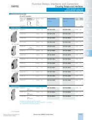
SIRIUS SC Semiconductor <strong>Switching</strong> <strong>Devices</strong>Function ModulesConvertersOverviewConverter <strong>for</strong> SIRIUS SC semiconductor switching devicesThis module is used to convert analog drive signals, such asthose output from many temperature controllers, <strong>for</strong> example,into a pulse-width-modulated digital signal. The connectedsemiconductor contactors and relays can there<strong>for</strong>e regulate theoutput of a load as a percentage.Area of applicationThe device is used <strong>for</strong> conversion from an analog input signal toan on/off ratio. The function module can only be used in conjunctionwith a 3RF21 semiconductor relay or a 3RF23 semiconductorcontactor.DesignMountingSimply snapping onto the 3RF21 semiconductor relays or 3RF23semiconductor contactors establishes the connections to thesemiconductor switching devices. The connector on the semiconductorswitching devices from the control circuit can be usedon the converter without rewiring.FunctionsThe analog value from a temperature controller is present at the0–10 V terminals. This controls the on-to-off period, as a functionof voltage. The period duration is predefined at one second.Conversion of the analog voltage is linear in the voltage rangefrom 0.1 to 9.9 V. At voltages below 0.1 V the connected switchingdevice is not activated, while at voltages above 9.9 V theconnected switching device is always activated.Technical specificationsControl input <strong>for</strong> converter und load monitoringType 3RF29 00-0EA18 3RF29 ..-0HA.Analog input V 0 ... 10 0 ... 10PermissiblerangeV -1 ... 11 -1 ... 11Input resistance kΩ 100 8Period duration s 1 1Selection and ordering dataRated operational current I e Rated operational voltage U e Rated control supplyvoltage U sAC/DC 24 VAVOrder No.PS*Weightper PUapprox.kgListPrice $- -3RF29 00-0EA18 1 unit 0.0253RF29 00-0EA18<strong>Siemens</strong> Industry, Inc.Industrial Controls CatalogProduct Category: SIRIUS SC7/23
SIRIUS SC Semiconductor <strong>Switching</strong> <strong>Devices</strong>Function ModulesLoad monitoringOverviewLoad monitoring <strong>for</strong> SIRIUS SC semiconductor switchingdevicesWith the addition of the load monitoring module many faults canbe quickly detected by monitoring a load circuit connected tothe semiconductor switching device. Examples include the failureof load elements (up to 6 in the basic version or up to 12 inthe extended version), alloyed power semiconductors, a lack ofvoltage or a break in a load circuit. A fault is indicated by one ormore LEDs and reported to the controller via a PLC-compatibleoutput.The operating principle is based on monitoring of the current.This figure is continuously compared with the reference valuestored once during commissioning by the simple press of a button.In order to detect the failure of one of several loads, the currentdecrease must be 1/6 (in the basic version) or 1/12 (in theextended version) of the reference value. In the event of a fault,a contact (NC) is actuated and one or more LEDs indicate thefault.Area of applicationThe device is used <strong>for</strong> monitoring one or more loads (partialloads). The function module can only be used in conjunction witha 3RF21 semiconductor relay or a 3RF23 semiconductor contactor.The devices with spring-loaded connections in the load circuitare not suitable <strong>for</strong> use with load monitoring modules.DesignMountingSimply snapping the load monitoring module onto the 3RF21semiconductor relays or 3RF23 semiconductor contactors establishesthe control connections to the semiconductor switchingdevices. Because of the special design, the straight-throughtrans<strong>for</strong>mer of the load monitoring module covers the lower mainpower connection. The cable to the load is simply pushedthrough and secured with the terminal screw.FunctionsThe function module is activated when an "ON" signal is applied(IN terminal). The module constantly monitors the current leveland compares this with the setpoint value.Start-upPressing the "Teach" button switches the device on; the currentthrough the semiconductor switching device is measured and isstored as the setpoint. During this process the two lower (red 1) )LEDs flash alternately; simultaneous maintained light from the 3(red 1) ) LEDs indicates the conclusion of the teaching process.The "Teach" button can also be used to switch on the connectedsemiconductor switching device briefly <strong>for</strong> test purposes. In thiscase the "ON" LED is switched on.Partial load faults, "basic" load monitoringIf a decrease of at least 1/6 of the stored setpoint value is detected,a fault is signaled. The fault is indicated via a "Fault" LEDand by activation of the fault signaling output.OKFaultLEDsPartial load failure/ Thyristorload short-circuit defectON/OFF -CurrentflowingGroup fault -Function is available- Function not availableMains failure/fuse rupturePartial load faults, "extended" load monitoringDepending on the setting of the "response time" potentiometer,a decrease of at least 1/12 of the stored setpoint value after a responsetime of between 100 ms and 3 s is signaled as a fault.The fault is indicated via a "Load" LED and by activation of thefault signaling output.The potentiometer can also be used to determine the responsebehavior of the fault signaling output. When delay values are setin the left-hand half, the fault signal is stored. This can only bereset by switching on and off by means of the control supply voltage.When settings are made on the right-hand side, the fault outputis automatically reset after the deviation has been corrected.Voltage compensation, "extended" load monitoringIn addition to the current, the load voltage is also monitored. Thismakes it possible to compensate <strong>for</strong> influences on the currentstrength resulting from voltage fluctuations.Thyristor faultIf a current greater than the residual current of the switching deviceis measured in the deenergized state, the device triggers athyristor fault after the set time delay. This means that the faultoutput is activated and the "Fault" ("Thyristor" 1) ) LED lights up.Supply faultIf no current is measured in the energized state, the device triggersa supply fault after the set time delay. This means that thefault output is activated and the "Fault" ("Supply" 1) ) LED lights up.1) "Extended" load monitoring-Selection and ordering dataRated Rated operationalvoltage U eoperationalcurrentI eRated control supplyvoltage U sAC 110 VRated control supplyvoltage U sAC/DC 24 V1) To order with mounted 3RF29 00-0RA88 cover, add -0KH0 to part number.Weightper PUapprox.Rated controlsupplyvoltage U sDC 24 VAV Order No. Order No. kg Order No. kgBasic load monitoringWeightper PUapprox.6 - - - 3RF29 06-0FA08 1 ) 1 unit 0.05020 - - - 3RF29 20-0FA08Extended load monitoring20 110 ... 230 3RF29 20-0GA33 3RF29 20-0GA13 1 unit 0.120 -20 400 ... 600 3RF29 20-0GA36 3RF29 20-0GA16 1 unit 0.120 -50 110 ... 230 3RF29 50-0GA33 3RF29 50-0GA13 1 unit 0.120 -50 400 ... 600 3RF29 50-0GA36 3RF29 50-0GA16 1 unit 0.120 -90 110 ... 230 3RF29 90-0GA33 3RF29 90-0GA13 1 unit 0.120 -90 400 ... 600 3RF29 90-0GA36 3RF29 90-0GA16 1 unit 0.120 -ListPrice $7/24 Product Category: SIRIUS SC<strong>Siemens</strong> Industry, Inc.Industrial Controls Catalog
<strong>Solid</strong>-<strong>State</strong> <strong>Switching</strong> <strong>Devices</strong> <strong>for</strong> <strong>Resistive</strong> <strong>Loads</strong>3RF29 Function ModulesHeating current monitoringOverviewHeating current monitoring <strong>for</strong> 3RF2 single-phase solidstateswitching devicesMany faults can be quickly detected by monitoring a load circuitconnected to the solid-state switching device, as made possiblewith this module. Examples include the failure of up to 6 load elements,alloyed power semiconductors, a lack of voltage or abreak in a load circuit. A fault is indicated by LEDs and reportedto the controller by way of a relay output (NC contact).The principle of operation is based on permanent monitoring ofthe current strength. This figure is continuously compared withthe reference value stored once during start-up. In order to detectthe failure of one of several loads, the current differencemust be 1/6 of the reference value. In the event of a fault, an outputis actuated and the LEDs indicate the fault.The heating current monitoring has a teach input and there<strong>for</strong>ediffers from the load monitoring. This remote teaching functionenables simple adjustment to changing loads without manualintervention.Special versions:deviations from the standard version3RF29 ..-0JA1.-1KK0If the current is below 50 % of the lower teach current during theteach routine, the device will go into "Standby" mode; the LOADLED will flicker. The device thus detects a non-connected load,e. g. channels not required <strong>for</strong> tool heaters, and does not signala fault. This mode can be reset by re-teaching.ApplicationThe device is used <strong>for</strong> monitoring one or more loads (partialloads). The function module can only be used in conjunction witha 3RF21 solid-state relay or a 3RF23 solid-state contactor. Thedevices with spring-loaded connections in the load circuit arenot suitable.Selection and ordering dataRated operationalcurrent I eRated operationalvoltage U eDT Order No. ListPrice $per PUVPS*Weightper PUapprox.AkgHeating current monitoring 1)Rated control supply voltage 24 V AC/DC16110 … 230A 3RF29 16-0JA13 1 unit 0.17516110 … 230A 3RF29 16-0JA13-1KK0 1 unit 0.17516400 … 600A 3RF29 16-0JA16-1KK0 1 unit 0.17532110 … 230A 3RF29 32-0JA13-1KK0 1 unit 0.17532400 … 600A 3RF29 32-0JA16 1 unit 0.17532400 … 600A 3RF29 32-0JA16-1KK0 1 unit 0.1751) Supplied without control connector. The control connector can be purchasedfrom Phoenix Contact by quoting Order No. 1982 790(2.5 HC/6-ST-5.08).Optional accessoriesVersionDT Order No. ListPrice $per PUSealable covers<strong>for</strong> function modules (not <strong>for</strong> converters)PS*Weightper PUapprox.kgB 3RF29 00-0RA88 10 units 0.0013RF29 00-0RA88* You can order this quantity or a multiple thereof.<strong>Siemens</strong> Industry, Inc.Industrial Controls Catalog7/25
<strong>Solid</strong>-<strong>State</strong> <strong>Switching</strong> <strong>Devices</strong> <strong>for</strong> <strong>Resistive</strong> <strong>Loads</strong>3RF29 Function ModulesPower controllersOverviewPower controllers <strong>for</strong> 3RF2 single-phase solid-state switchingdevicesThe power controller is a function module <strong>for</strong> the autonomouspower control of complex heating systems and inductive loads.The following functions have been integrated:• Power controller <strong>for</strong> adjusting the power of the connected load.Here, the setpoint value is set with a rotary knob on the moduleas a percentage with reference to the 100 % power stored asa setpoint value.• Inrush current limitation: With the aid of an adjustable voltageramp, the inrush current is limited by means of phase control.This is useful above all with loads such as lamps or infraredlamps which have an inrush transient current.• Load circuit monitoring <strong>for</strong> detecting load failure, partial loadfaults, alloyed power semiconductors, lack of voltage or abreak in the load circuit.Special versions:deviations from the standard version3RF29 04-0KA13-0KC0During the teaching process the connected solid-state relay orcontactor is not activated; i. e. no current flow takes place. Nocurrent reference value is stored. No part-load monitoring!3RF29 ..-0KA1.-0KT0No part-load monitoring!ApplicationThe power controller can be used <strong>for</strong>:• Complex heating systems• Inductive loads• <strong>Loads</strong> with temperature-dependent resistor• <strong>Loads</strong> with ageing after long-time service• Simple indirect control of temperatureThe power controller can be used on the instantaneously switching3RF21 and 3RF23 solid-state switching devices (singlephase).If only the full-wave operating mode is used, the powercontroller can also be used on the "zero-point switching" solidstaterelays and contactors.Power controlThe power controller adjusts the power in the connected load bymeans of a solid-state switching device depending on the setpointselection. It does not compensate <strong>for</strong> changes in the mainsvoltage or load resistance. The setpoint value can be predefinedexternally as a 0 to 10 V signal or internally by means of a potentiometer.Depending on the setting of the potentiometer (t R ), thecontrol is carried out according to the principle of full-wave controlor generalized phase control.Full-wave controlIn this operating mode the output is adjusted to the required setpointvalue changing the on-to-off period. The period duration ispredefined at one second.Generalized phase controlIn this operating mode the output is adjusted to the required setpointvalue by changing the current flow angle. In order to observethe limit values of the conducted interference voltage <strong>for</strong>industrial networks, the load circuit must include a reactor with arating of at least 200 µH.Selection and ordering dataPower controllersRated operationalcurrent I eARated operationalvoltage U eDT Order No. ListPrice $per PUVPS*Weightper PUapprox.Rated control supply voltage 24 V AC/DC4 110 … 230A 3RF29 04-0KA13-0KC0 1 unit 0.1754 A 3RF29 04-0KA13-0KT0 1 unit 0.17520A 3RF29 20-0KA13 1 unit 0.17550A 3RF29 50-0KA13 1 unit 0.17590A 3RF29 90-0KA13 1 unit 0.17520400 … 600A 3RF29 20-0KA16 1 unit 0.17550A 3RF29 50-0KA16 1 unit 0.17550A 3RF29 50-0KA16-0KT0 1 unit 0.17590A 3RF29 90-0KA16 1 unit 0.175kgOptional accessoriesVersionDT Order No. ListPrice $per PUSealable covers<strong>for</strong> function modules (not <strong>for</strong> converters)PS*Weightper PUapprox.kgB 3RF29 00-0RA88 10 units 0.0013RF29 00-0RA88* You can order this quantity or a multiple thereof.7/26<strong>Siemens</strong> Industry, Inc.Industrial Controls Catalog
SIRIUS SC Semiconductor <strong>Switching</strong> <strong>Devices</strong>Function ModulesPower control regulatorsOverviewPower controllers <strong>for</strong> SIRIUS SC semiconductor switchingdevicesThis module provides similar functionality to a power control regulator.The following functions are integrated:Power control regulator with proportional-action control <strong>for</strong> adjustingthe power of the connected load. Here, the setpoint is setwith a rotary knob on the module as a percentage with referenceto the 100% power stored as a setpoint. In this way the power iskept constant even in the event of voltage fluctuations or achange in load resistance.Inrush current limitation: With the aid of an adjustable voltageramp, the inrush current is limited by means of phase control.This is useful above all with loads such as lamps which have aninrush transient current.Load circuit monitoring <strong>for</strong> detecting load failure, alloyed powersemiconductors, lack of voltage or a break in the load circuit.Area of applicationThe power controller adjusts the current in the connected loadby means of a semiconductor switching device depending on asetpoint. This compensates <strong>for</strong> changes in the mains voltage orin the load resistance. The setpoint can be predefined externallyas a 0 to 10 V signal or internally by means of a potentiometer.Depending on the setting of the potentiometer (t R ), the adjustmentis carried out according to the principle of full-wave controlor generalized phase control.Full-wave controlIn this operating mode the output is adjusted to the required setpointby changing the on-to-off period. The period duration ispredefined at one second.Generalized phase controlIn this operating mode the output is adjusted to the required setpointby changing the current flow angle. In order to observe thelimit values of the conducted interference voltage <strong>for</strong> industrialpower systems, a choke rated at at least 200 µH must be includedin the load circuit.DesignMountingEasy snapping onto the 3RF21 semiconductor relays or 3RF23semiconductor contactors establishes the connections to thesemiconductor switching devices. Because of the special design,the straight-through trans<strong>for</strong>mer of the power controllermodule covers the lower main power connection. The cable tothe load is simply pushed through and secured with the terminalscrew.FunctionsStart-upPressing the "Teach" button switches the device on; the currentthrough the semiconductor switching device and the mains voltageare detected and stored. The resultant output is taken as the100% output <strong>for</strong> the setpoint selection. During this process thetwo lower red LEDs flash alternately. Simultaneous maintainedlight from the three red LEDs indicates the completion of the"Teach" process.The "Teach" button can also be used to switch on the connectedsemiconductor switching device briefly <strong>for</strong> test purposes. In thiscase the "ON" LED is switched on.Setpoint selectionThe setting on the setpoint potentiometer (P) determines how thesetpoint selection is to be made:External setpoint selectionAt 0 % the setpoint selection is set via an external 0 – 10 V analogsignal (terminals IN / 0 – 10 V). The device is switched on and offvia the power supply (terminals A1 / A2).Internal setpoint selectionAbove 0 % the setpoint is set using the potentiometer. To allowthis, the potential at terminal A1 must additionally be applied atthe IN terminal. After removal of the "ON" signal, the switchingmodule is switched off.Inrush current limitationThe ramp time (t R ) <strong>for</strong> a voltage ramp on switching on is set withthe potentiometer <strong>for</strong> the purpose of inrush current limitation. If atime longer than 0 s is set, the device operates according to thephase-angle principle. If 0 s is set, there is no voltage ramp andthe device operates according to the principle of full-wave control.Load faultIf upon switching on with voltage applied the current flowing isnot greater than the residual current of the switching device, thedevice triggers a load fault. The fault relay is activated and the"Load" LED lights up.Thyristor faultIf a current greater than the residual current of the switching deviceis measured in the deenergized state, the device triggers athyristor fault. The fault relay is activated and the "Thyristor" LEDlights up.Supply faultIf no current is measured in the energized state, the device triggersa supply fault. The fault relay is activated and the "Supply"LED lights up.Selection and ordering dataRated operational currentI eRated operational voltage U e Rated control supplyvoltage U sAC 110 VAPower controllers 1 )Rated control supplyvoltage U sAC/DC 24 VV Order No. Order No. kgWeightper PUapprox.20110 ... 2303RF29 20-0HA33 3RF29 20-0HA13 1 unit 0.12020400 ... 6003RF29 20-0HA36 3RF29 20-0HA16 1 unit 0.12050110 ... 2303RF29 50-0HA33 3RF29 50-0HA13 1 unit 0.12050400 ... 6003RF29 50-0HA36 3RF29 50-0HA16 1 unit 0.12090110 ... 2303RF29 90-0HA33 3RF29 90-0HA13 1 unit 0.12090400 ... 6003RF29 90-0HA36 3RF29 90-0HA16 1 unit 0.120ListPrice $1) Optional sealable cover - 3RF29 00-0RA88 can be used.<strong>Siemens</strong> Industry, Inc.Industrial Controls CatalogProduct Category: SIRIUS SC7/27
Controls — <strong>Solid</strong>-<strong>State</strong> <strong>Switching</strong> <strong>Devices</strong>3RF29 Function ModulesPower control regulatorsOverviewPower control regulators <strong>for</strong> SIRIUS solid-state switchingdevicesThe power control regulator is a function module <strong>for</strong> the autonomouspower control regulation of complex heating systems andinductive loads, <strong>for</strong> the operation of loads with temperaturedependentresistors or long-term aging, and <strong>for</strong> simple indirecttemperature control.The power control regulator can be used on the 3RF21 and3RF23 instantaneous switching solid-state switching devices(single-phase). If only the full-wave control mode is used, thepower control regulator can also be used on the zero-pointswitchingsolid-state relays and contactors.ApplicationThe power control regulator sets the load current of the solidstateswitching device depending on a setpoint value as apercentage. Changes in the mains voltage or in the load resistanceare not compensated in this case. The modulation, theOn/off ratio or the phase angle, remains unchanged in accordancewith the setpoint. The autonomous power control regulationis per<strong>for</strong>med between 0 and 100 % of the setpoint valueFull-wave controlIf the left potentiometer t R is set to 0 s (= far left), the powercontrol regulator works according to the principle of full-wavecontrol. The power set, be it internal or external, is converted intoa pulse-width-modulated digital signal. The power control regulatorcontrols the On and Off time of the solid-state switchingdevice within a fixed period duration of 1 s so that the specifiedpower is applied to the load. The "ON" LED flashes in the samerhythm as the solid-state switching device switches on and off.Generalized phase controlIf the left potentiometer t R is set to higher than 0 s, the powercontrol regulator works according to the principle of generalizedphase control. With generalized phase control, a choke rated atat least 200 µH must be included in the load circuit in order toobserve the limit values of the conducted interference voltage<strong>for</strong> industrial networks.DesignMountingEasy snapping onto the 3RF21 solid-state relays or 3RF23 solidstatecontactors establishes the connections to the solid-stateswitching devices. Because of the special design, the straightthroughtrans<strong>for</strong>mer of the function module covers the lowermain power connection. The cable to the load is simply pushedthrough and secured with the terminal screw.FunctionSetpoint selectionThe setpoint is selected either internally using the right-handpotentiometer P with 0 ... 100 % on the module or externallythrough the analog input 0 ... 10 V.100 % corresponds in full-wave control to permanently On andin generalized phase control to a conduction angle of 180° andhence maximum power.When the setpoint is selected internally the module is controlledthrough the IN terminal. The terminal 10 then has no function.Conduction angle180°90°0°Modulation100%500< 0,1 5,0 V > 9,9External setpoint of analog voltage 0 ... 10 V0 50 % 100Internal setpoint of potentiometer PInput characteristic curveWhen the setpoint is selected externally (potentiometer P set farleft = 0 %) the module is controlled by applying the analogvoltage 0 ... 10 V. 0 ... 10 V corresponds to 0 ... 100 % power.Conversion of the voltage is linear between 0.1 and 9.9 V. Below0.1 V the switching device remains off; at voltages above 9.9 Vthe power is always set to 100 %.Inrush current limitationThe ramp time (t R ) <strong>for</strong> a voltage ramp on switching on is set withthe left potentiometer <strong>for</strong> the purpose of inrush current limitation.The set time refers to a power of 100 %. If, <strong>for</strong> example, a ramptime of 10 s is set and the selected power is 60 %, then a powerof 60 % is reached after approx. 6 s.Line and thyristor monitoringThe power control regulator recognizes supply failures andthyristor faults. The faults are indicated by the LEDs on the moduleand the fault output is activated.NSB0_016937/28<strong>Siemens</strong> Industry, Inc.Industrial Controls Catalog
SIRIUS SC Semiconductor <strong>Switching</strong> <strong>Devices</strong>Semiconductor Relays22.5 mm semiconductor relaystechnical dataOverview22.5 mm semiconductor relaysWith its compact design, which stays the same even at currentsof up to 88 A, the 3RF21 semiconductor relay is the ultimate inspace-saving construction, at a width of 22.5 mm. The logicalconnection arrangement, with the power infeed from above andconnection of the load from below, ensures clean installation inthe control cabinet.Technical specificationsType 3RF21 ..-1.... 3RF21 ..-2.... 3RF21 ..-3....General dataAmbient temperatureduring operation, derating from 40 °C °C -25 ... +60whenstored°C -55 ... +80Site altitude m 0 ... 1000; derating from 1000Shock resistanceg/ms 15/11acc. to IEC 60068-2-27Vibration resistanceg 2acc. to IEC 60068-2-6Degree of protectionIP20Electromagnetic compatibility (EMC)Emitted interference• Conducted interference voltageClass A <strong>for</strong> industrial applicationsacc. to IEC 60947-4-3• Emitted, high-frequency interferenceClass A <strong>for</strong> industrial applicationsvoltage acc. to IEC 60947-4-3Noise immunity• Electrostatic dischargekV Contact discharge 4; air discharge 8; behavior criterion 2acc. to IEC 61000-4-2(corresponds to degree of severity 3)• Induced RF fields acc. to IEC 61000-4-6 MHz 0.15 ... 80; 140 dBµV; behavior criterion 1• Burst acc. to IEC 61000-4-4 kV 2/5.0 kHz; behavior criterion 1• Surge acc. to IEC 61000-4-5 kV Conductor - ground 2; conductor - conductor 1; behavior criterion 2Connection technique Screw-type connection Spring-loaded connection Ring cable connectionMain contact connectionConductor cross-section<strong>Solid</strong>mm2 2 x (1.5 ... 2.5), 2 x (2.5 ... 6) 2 x (0,5 ... 2.5) -Finely stranded with end sleeve mm 2 2 x (1.5 ... 2.5), 2 x (2.5 ... 6), 2 x (0.5 ... 1.5) -1 x 10Finely stranded without end sleeves mm 2 2 x (0.5 ... 2.5) -<strong>Solid</strong> or stranded AWG conductors AWG 2 x (14 ... 10) 2 x (18 ... 14) -Insulation stripping length mm 10 10 -Terminal screw M 4 - M 5• Tightening torqueNm 2 ... 2.5 - 2 ... 2.5lb.in 18 ... 22 - 18 ... 22Cable lug•DIN - - DIN 46234-5-2.5, -5-6, -5-10, -5-16, -5-25•JIS - - JIS C 2805 R 2-5, 5.5-5, 8-5, 14-5Auxiliary/control contact connectionsConductor cross-section mm 2AWG1x (0.5 ... 2.5); 2x (0.5 ... 1)20 ... 120.5 ... 1.520 ... 12Insulation stripping length mm 7 10 7Terminal screw M 3 - M 3• Tightening torqueNm 0.5 ... 0.6 - 0.5 ... 0.6lb.in 4.5 ... 5.3 - 4.5 ... 5.31x (0.5 ... 2.5); 2x (0.5 ... 1)20 ... 12Type 3RF21 ..-....2 3RF21 ..-....4 3RF21 ..-....5 3RF21 ..-....6Main circuitRated operational voltage U e V 24 ... 230 230 ... 460 48 ... 600 400 ... 600• Tolerance% -15 / +10• Rated frequencyHz 50/60Rated insulation voltage U i V 600Blocking voltage V 800 1200 1200 1600Rate of voltage rise V/µs 1000<strong>Siemens</strong> Industry, Inc.Industrial Controls Catalog7/29
<strong>Solid</strong>-<strong>State</strong> <strong>Switching</strong> <strong>Devices</strong> <strong>for</strong> <strong>Resistive</strong> <strong>Loads</strong><strong>Solid</strong>-<strong>State</strong> Relays3RF21 solid-state relays,single-phase, 22.5 mmOrder No.1)I max I e acc. to IEC 60947-4-3 I e acc. to UL/CSA Power loss Minimum load Leakage currentat R thha /T u = 40 °C at R thha /T u = 40 °C at R thha /T u = 50 °C at I maxcurrentA K/W A K/W A K/W W A mAMain circuit3RF21 20-..... 20 2.0 20 1.7 20 1.3 28.6 0.1 103RF21 30-1.... 30 1.1 30 0.79 30 0.56 44.2 0.5 103RF21 50-1.... 50 0.68 50 0.48 50 0.33 66 0.5 103RF21 50-2.... 50 0.68 20 2.6 20 2.9 66 0.5 103RF21 50-3.... 50 0.68 50 0.48 50 0.33 66 0.5 103RF21 70-1.... 70 0.40 50 0.77 50 0.6 94 0.5 103RF21 90-1.... 88 0.33 50 0.94 50 0.85 118 0.5 103RF21 90-2.... 88 0.33 20 2.8 20 3.5 118 0.5 103RF21 90-3.... 88 0.33 88 0.22 83 0.19 118 0.5 101) I max provides in<strong>for</strong>mation about the per<strong>for</strong>mance of the solid-state relay.The actual permitted rated operational current I e can be smaller dependingon the connection method and cooling conditions.Order No. Rated impulse withstand capacity I tsm I 2 t valueAA sMain circuit3RF21 20-..... 200 2003RF21 30-..A.2 300 4503RF21 30-..A.4 300 4503RF21 30-..A.5 300 4503RF21 30-..A.6 400 8003RF21 50-..... 600 18003RF21 70-..A.2 1200 72003RF21 70-..A.4 1200 72003RF21 70-..A.5 1200 72003RF21 70-..A.6 1150 66003RF21 90-..... 1150 6600Note: The required heat sinks <strong>for</strong> the corresponding load currentscan be determined from the characteristic curves,page 4/10. The minimum thickness values <strong>for</strong> the mounting surfacemust be observed.Type 3RF21 ..-....2 3RF21 ..-....4 3RF21 ..-....5 3RF21 ..-....6Main circuitRated operational voltage U e V 24 ... 230 48 ... 460 48 ... 600 48 ... 600• Operating rangeV 20 ... 253 40 ... 506 40 ... 660 40 ... 660• Rated frequencyHz 50/60 ± 10 %Rated insulation voltage U i V 600Blocking voltage V 800 1200 1600Rage of voltage rise V/µs 1000Type 3RF21 ..-...0. 3RF21 ..-...1. 3RF21 ..-...2. 3RF21 ..-...4.Control circuitMethod of operation DC operation AC/DC operation AC operation DC operationRated control supply voltage U s V 24 acc. toEN 61131-224 AC 24 DC 110 ... 230 4 ... 30Rated frequencyof the control supply voltage1) Applies to the version "Low Power" 3RF21 ..-.AA..-0KN0.2) Only <strong>for</strong> zero-point-switching devices.Hz -- 50/60± 10 %-- 50/60 ± 10 % --Control supply voltage, max. V 30 26.5 AC 30 DC 253 30Typical actuating current mA 20 / Low Power: 6.5 1) 20 20 15 20Response voltage V 15 14 AC 15 DC 90 4Drop-out voltage V 5 5 AC 5 DC 40 1Operating times• ON-delayms 1 + max. onehalf-wave 2)• OFF-delayms 1 + max. onehalf-wave10 + max. onehalf-wave 2)15 + max. onehalf-wave40 + max. onehalf-wave 2)40 + max. onehalf-wave1 + max. onehalf-wave 2)1 + max. onehalf-wave7/30 <strong>Siemens</strong> Industry, Inc.Industrial Controls Catalog
SIRIUS SC Semiconductor <strong>Switching</strong> <strong>Devices</strong>Semiconductor Relays22.5 mm semiconductor relaystechnical dataOrder No.AccessoriesConvertersLoad monitorsBasicExtendedType current = 20 A3RF21 2.-1..02 3RF29 00-0EA18 3RF29 20-0FA08 3RF29 20-0GA133RF21 2.-1..04 3RF29 00-0EA18 3RF29 20-0FA08 3RF29 20-0GA163RF21 2.-1..22 - - 3RF29 20-0GA333RF21 2.-1..24 - - 3RF29 20-0GA363RF21 2.-2..02 3RF29 00-0EA18 - -3RF21 2.-2..04 3RF29 00-0EA18 - -3RF21 2.-3..02 3RF29 00-0EA18 - 3RF29 20-0GA133RF21 2.-3..04 3RF29 00-0EA18 - 3RF29 20-0GA163RF21 2.-3..22 - - 3RF29 20-0GA333RF21 2.-3..24 - - 3RF29 20-0GA36Type current = 30 A3RF21 3.-1..02 3RF29 00-0EA18 3RF29 20-0FA08 3RF29 50-0GA133RF21 3.-1..04 3RF29 00-0EA18 3RF29 20-0FA08 3RF29 50-0GA163RF21 3.-1..06 3RF29 00-0EA18 3RF29 20-0FA08 3RF29 50-0GA163RF21 3.-1..22 - - 3RF29 50-0GA333RF21 3.-1..24 - - 3RF29 50-0GA363RF21 3.-1..26 - - 3RF29 50-0GA36Type current = 50 A3RF21 5.-1..02 3RF29 00-0EA18 3RF29 20-0FA08 3RF29 50-0GA133RF21 5.-1..04 3RF29 00-0EA18 3RF29 20-0FA08 3RF29 50-0GA163RF21 5.-1..06 3RF29 00-0EA18 3RF29 20-0FA08 3RF29 50-0GA163RF21 5.-1..22 - - 3RF29 50-0GA333RF21 5.-1..24 - - 3RF29 50-0GA363RF21 5.-1..26 - - 3RF29 50-0GA363RF21 5.-2..02 3RF29 00-0EA18 - -3RF21 5.-2..04 3RF29 00-0EA18 - -3RF21 5.-2..06 3RF29 00-0EA18 - -3RF21 5.-3..02 3RF29 00-0EA18 - 3RF29 50-0GA133RF21 5.-3..06 3RF29 00-0EA18 - 3RF29 50-0GA163RF21 5.-3..04 3RF29 00-0EA18 - 3RF29 50-0GA163RF21 5.-3..22 - - 3RF29 50-0GA333RF21 5.-3..24 - - 3RF29 50-0GA363RF21 5.-3..26 - - 3RF29 50-0GA36Type current = 70 A3RF21 7.-1..02 3RF29 00-0EA18 3RF29 20-0FA08 3RF29 90-0GA133RF21 7.-1..04 3RF29 00-0EA18 3RF29 20-0FA08 3RF29 90-0GA163RF21 7.-1..06 3RF29 00-0EA18 3RF29 20-0FA08 3RF29 90-0GA163RF21 7.-1..22 - - 3RF29 90-0GA333RF21 7.-1..24 - - 3RF29 90-0GA363RF21 7.-1..26 - - 3RF29 90-0GA36Type current = 90 A3RF21 9.-1..02 3RF29 00-0EA18 3RF29 20-0FA08 3RF29 90-0GA133RF21 9.-1..04 3RF29 00-0EA18 3RF29 20-0FA08 3RF29 90-0GA163RF21 9.-1..06 3RF29 00-0EA18 3RF29 20-0FA08 3RF29 90-0GA163RF21 9.-1..22 - - 3RF29 90-0GA333RF21 9.-1..24 - - 3RF29 90-0GA363RF21 9.-1..26 - - 3RF29 90-0GA363RF21 9.-2..02 3RF29 00-0EA18 - -3RF21 9.-2..06 3RF29 00-0EA18 - -3RF21 9.-2..04 3RF29 00-0EA18 - -3RF21 9.-3..02 3RF29 00-0EA18 - 3RF29 90-0GA133RF21 9.-3..04 3RF29 00-0EA18 - 3RF29 90-0GA163RF21 9.-3..06 3RF29 00-0EA18 - 3RF29 90-0GA163RF21 9.-3..22 - - 3RF29 90-0GA333RF21 9.-3..26 - - 3RF29 90-0GA363RF21 9.-3..24 - - 3RF29 90-0GA36<strong>Siemens</strong> Industry, Inc.Industrial Controls Catalog7/31
<strong>Solid</strong>-<strong>State</strong> <strong>Switching</strong> <strong>Devices</strong> <strong>for</strong> <strong>Resistive</strong> <strong>Loads</strong><strong>Solid</strong>-<strong>State</strong> Relays3RF21 solid-state relays,single-phase, 22.5 mmFused version with semiconductor protection (similar to type of coordination "2") 1)The semiconductor protection <strong>for</strong> the SIRIUS controls can beused with different protective devices. This allows protection bymeans of LV HRC fuses of gG operational class or miniature circuitbreakers. <strong>Siemens</strong> recommends the use of special SITORsemiconductor fuses. The table below lists the maximum permissiblefuses <strong>for</strong> each SIRIUS control.Order No. All-range fuses Semiconductor fuses/partial-range fusesLV HRC design Cylindrical design LV HRC design Cylindrical designIf a fuse is used with a higher rated current than specified, semiconductorprotection is no longer guaranteed. However, smallerfuses with a lower rated current <strong>for</strong> the load can be used withoutproblems.For protective devices with gG operational class and <strong>for</strong> SITOR3NE1 all-range fuses, the minimum cross-sections <strong>for</strong> the conductorto be connected must be taken into account.gR/SITOR gR/NEOZED 2) aR/SITOR aR/SITOR aR/SITOR aR/SITOR3NE1SILIZED5SE13NE810 mm x 38 mm3NC1 014 mm x 51 mm3NC1 422 mm x 58 mm3NC2 23RF21 20-...2 3NE1 814-0 5SE1 325 3NE8 015-1 3NC1 020 3NC1 420 3NC2 2203RF21 20-...4 3NE1 813-0 4) 5SE1 320 3NE8 015-1 3NC1 016 4) 3NC1 420 3NC2 2203RF21 20-....5 3) 3NE1 813-0 4) 5SE1 320 3NE8 015-1 3NC1 016 4) 3NC1 420 3NC2 2203RF21 30-...2 3NE1 815-0 4) 5SE1 335 3NE8 003-1 3NC1 032 3NC1 432 3NC2 2323RF21 30-...4 3NE1 815-0 4) 5SE1 325 4) 3NE8 003-1 3NC1 025 4) 3NC1 430 3NC2 2323RF21 30-....5 3) 3NE1 815-0 4) 5SE1 325 4) 3NE8 003-1 3NC1 025 4) 3NC1 430 3NC2 2323RF21 30-...6 3NE1 815-0 4) -- 3NE8 003-1 3NC1 032 3NC1 432 3NC2 2323RF21 50-...2 3NE1 817-0 5SE1 350 3NE8 017-1 -- 3NC1 450 3NC2 2503RF21 50-...4 3NE1 802-0 4) 5SE1 335 4) 3NE8 017-1 -- 3NC1 450 3NC2 2503RF21 50-....5 3) 3NE1 802-0 4) 5SE1 335 4) 3NE8 017-1 -- 3NC1 450 3NC2 2503RF21 50-...6 3NE1 803-0 4) -- 3NE8 017-1 -- 3NC1 450 3NC2 2503RF21 70-...2 5) 3NE1 820-0 5SE1 363 4) 3NE8 020-1 -- -- 3NC2 2803RF21 70-...4 5) 3NE1 020-2 5SE1 363 4) 3NE8 020-1 -- -- 3NC2 2803RF21 70-....5 3)5) 3NE1 020-2 -- 3NE8 020-1 -- -- 3NC2 2803RF21 70-...6 5) 3NE1 020-2 -- 3NE8 020-1 -- -- 3NC2 2803RF21 90-...2 5) 3NE1 021-2 -- 3NE8 021-1 -- -- 3NC2 2003RF21 90-...4 5) 3NE1 021-2 -- 3NE8 021-1 -- -- 3NC2 280 4)3RF21 90-....5 3)5) 3NE1 021-2 -- 3NE8 021-1 -- -- 3NC2 280 4)3RF21 90-...6 5) 3NE1 817-0 4) -- 3NE8 021-1 -- -- 3NC2 280 4)Order No.Cable and line protection fusesLV HRC design 4) Cylindrical design 4) DIAZED 4)gG gG gG gG quick3NA210 mm x 38 mm3NW6 014 mm x 51 mm3NW6 1Suitable fuse holders, fuse bases and controls can be found inCatalog LV 1, Chapter 19.1) Type of coordination "2" according to EN 60947-4-1:In the event of a short-circuit, the controls in the load feeder must notendanger persons or the installation. They must be suitable <strong>for</strong> furtheroperation. For fused configurations, the protective device must bereplaced.2) For use only with operational voltage U e up to 400 V.3) For use only with operational voltage U e up to 506 V.4) These fuses have a smaller rated current than the solid-state relays.5) These versions can also be protected against short-circuits with miniaturecircuit breakers as described in the notes on "SIRIUS <strong>Solid</strong>-<strong>State</strong>Contactors → Special Version Short-Circuit Resistant".22 mm x 58 mm3NW6 23RF21 20-...2 3NA2 803 3NW6 000-1 3NW6 101-1 -- 5SB1 413RF21 20-...4 3NA2 801 -- 3NW6 101-1 -- 5SB1 413RF21 20-....5 3) 3NA2 801 -- 3NW6 101-1 -- 5SB1 413RF21 30-...2 3NA2 803 -- 3NW6 103-1 -- 5SB1 713RF21 30-...4 3NA2 803 -- 3NW6 101-1 -- 5SB1 713RF21 30-....5 3) 3NA2 803 -- 3NW6 101-1 -- 5SB1 713RF21 30-...6 3NA2 803-6 -- -- -- --3RF21 50-...2 3NA2 810 -- 3NW6 107-1 3NW6 207-1 5SB3 113RF21 50-...4 3NA2 807 -- -- 3NW6 205-1 5SB3 113RF21 50-....5 3) 3NA2 807 -- -- 3NW6 205-1 5SB3 113RF21 50-...6 3NA2 807-6 -- -- -- --3RF21 70-...2 5) 3NA2 817 -- -- 3NW6 217-1 5SB3 313RF21 70-...4 5) 3NA2 812 -- -- 3NW6 212-1 5SB3 313RF21 70-....5 3)5) 3NA2 812 -- -- 3NW6 212-1 --3RF21 70-...6 5) 3NA2 812-6 -- -- -- --3RF21 90-...2 5) 3NA2 817 -- -- 3NW6 217-1 --3RF21 90-...4 5) 3NA2 812 -- -- 3NW6 212-1 --3RF21 90-....5 3)5) 3NA2 812 -- -- 3NW6 212-1 --3RF21 90-...6 5) 3NA2 812-6 -- -- -- --5SB7/32 <strong>Siemens</strong> Industry, Inc.Industrial Controls Catalog
■ Overview45 mm semiconductor relaysThe semiconductor relays with a width of 45 mm provide <strong>for</strong>connection of the power supply lead and the load from above.This makes it easy to retrofit existing semiconductor relays. Theconnection of the control cable also saves space in much thesame way as the 22.5 mm design, as it is simply plugged on.■ Technical specificationsSIRIUS SC Semiconductor <strong>Switching</strong> <strong>Devices</strong>Semiconductor RelaysType3RF20General dataAmbient temperatureduring operation, derating at 40 °C °C -25 ... +60when stored °C -55 ... +80Site altitude m 0 ... 1000; derating from 1000Shock resistanceg/ms 15/11acc. to IEC 60068-2-27Vibration resistanceg 2acc. to IEC 60068-2-6Degree of protectionIP20Electromagnetic compatibility (EMC)Emitted interference• Conducted interference voltage IECClass A <strong>for</strong> industrial applicationsacc. to 60947-4-3• Emitted, high-frequency interferenceClass A <strong>for</strong> industrial applicationsvoltage acc. to IEC 60947-4-3Noise immunity• Electrostatic dischargekV Contact discharge 4; air discharge 8; behavior criterion 2acc. to IEC 61000-4-2(corresponds to degree of severity 3)• Induced RF fields acc. to IEC 61000-4-6 MHz 0.15 ... 80; 140 dBµV; behavior criterion 1• Burst acc. to IEC 61000-4-4 kV 2/5.0 kHz; behavior criterion 1• Surge acc. to IEC 61000-4-5 kV Conductor - ground 2; conductor - conductor 1; behavior criterion 2Connection, main contacts, screw connectionConductor cross-section<strong>Solid</strong> mm 2 2 x (1.5 ... 2.5); 2 x (2.5 ... 6)Finely stranded with end sleeve mm 2 2 x (1.5 ... 2.5); 2 x (2.5 ... 6); 1 x 10<strong>Solid</strong> or stranded AWG conductors AWG 2 x (14 ... 10)Insulation stripping length mm 10Terminal screw M 4• Tightening torque Nm 2 ... 2.5lb.in 18 ... 22Connection, auxiliary/control contacts,screw connectionConductor cross-section mm 2 1x (0.5 ... 2.5); 2x (0.5 ... 1.0); AWG 20 ... 12Insulation stripping length mm 7Terminal screw M 3• Tightening torque Nm 0.5 ... 0.6lb.in 4.5 ... 5.345 mm semiconductor relaystechnical dataType 3RF20 .0-1AA.2 3RF20 .0-1AA.4 3RF20..-....5 3RF20 .0-1AA.6Main circuitRated operational voltage U e V 24 ... 230 230 ... 460 48 ... 600 400 ... 600• Tolerance % -15/+10• Rated frequency Hz 50/60Rated insulation voltage U i V 600Blocking voltage V 800 1200 1200 1600Rage of voltage rise V/µs 1000<strong>Siemens</strong> Industry, Inc.Industrial Controls Catalog7/33
SIRIUS SC Semiconductor <strong>Switching</strong> <strong>Devices</strong>Semiconductor Relays45 mm semiconductor relaystechnical dataOrder No.1)I max I e to IEC 60947-4-3 I e to UL/CSA Power loss Minimum load Leakage currentat R thha /T u = 40 °C at R thha /T u = 40 °C at R thha /T u = 50 °C <strong>for</strong> I maxcurrentA K/W A K/W A K/W W A mAMain circuit3RF20 20-1AA.. 20 2.0 20 2.0 20 1.7 28.6 0.5 103RF20 30-1AA.. 30 1.1 30 1.1 30 0.88 44.2 0.5 103RF20 50-1AA.. 50 0.68 50 0.68 50 0.53 66 0.5 103RF20 70-1AA.. 70 0.4 50 0.95 50 0.8 94 0.5 103RF20 90-1AA.. 88 0.33 50 1.25 50 1.02 118 0.5 101) I max provides in<strong>for</strong>mation about the per<strong>for</strong>mance of the semiconductorrelay. The actual permitted operational current I e can be smaller dependingon the connection method and cooling conditions.Order No.Main circuitRated impulse withstandcapacity I tsmAI 2 t valueA2 s3RF20 20-1AA.. 200 2003RF20 30-1AA.2 300 4503RF20 30-1AA.4 300 4503RF20 30-1AA.6 400 8003RF20 50-1AA.. 600 18003RF20 70-1AA.2 1200 72003RF20 70-1AA.4 1200 72003RF20 70-1AA.6 1150 66003RF20 90-1AA.. 1150 6600Type 3RF20 .0-1AA0. 3RF20 .0-1AA4. 3RF20 .0-1AA2.Control circuitMethod of operation DC operation DC operation AC operationRated control supply voltage U s V 24 acc. to EN 61131-2 4 ... 30V DC 110 ... 230Max. rated control voltage V 30 30 253Rated control current at U s mA 15 15 6Rated frequency ofthe control supply voltageHz- - 50/60Response voltage V 15 4 90c urrentmA >2 >2 2Drop-out voltage V 5 1 40Operating timesclosing timems 1 + max. one half wave 1 + max. one half wave 40 + max. one half waveopening timems 1 + max. one half wave 1 + max. one half wave 40 + max. one half waveFused design with semiconductor protectionOrder No.All-range fuseLV designgR/SITOR3NE1Semiconductor protection fuseCylindrical design10 × 38 mmaR/SITOR3NC1 014 × 51 mmaR/SITOR3NC1 422 × 58 mmaR/SITOR3NC2 2Cable and line protection fuseLV design Cylindrical designgL/gG/3NA10 × 38 mmgL/gG 3NW14 × 51 mmgL/gG 3NW22 × 58 mmgL/gG 3NWDIAZED quick5SB3RF20 20-1AA.2 3NE1 814-0 3NC1 020 3NC1 420 3NC2 220 3NA2 803 3NW6 001-1 3NW6 101-1 - 5SB1 713RF20 20-1AA.4 3NE1 813-0 3NC1 016 3NC1 420 3NC2 220 3NA2 801 - 3NW6 101-1 - 5SB1 413RF20 30-1AA.2 3NE1 815-0 3NC1 032 3NC1 432 3NC2 232 3NA2 803 - 3NW6 103-1 - 5SB3 113RF20 30-1AA.4 3NE1 815-0 3NC1 025 3NC1 432 3NC2 232 3NA2 803 - 3NW6 101-1 - 5SB1 713RF20 30-1AA.6 3NE1 815-0 3NC1 032 3NC1 432 3NC2 232 3NA2 803-6 - - - -3RF20 50-1AA.2 3NE1 817-0 - 3NC1 450 3NC2 250 3NA2 810 - 3NW6 107-1 3NW6 207-1 5SB3 213RF20 50-1AA.4 3NE1 802-0 - 3NC1 450 3NC2 250 3NA2 807 - - 3NW6 205-1 5SB3 113RF20 50-1AA.6 3NE1 803-0 - 3NC1 450 3NC2 250 3NA2 807-6 - - - -3RF20 70-1AA.2 2) 3NE1 820-0 - - 3NC2 280 3NA2 817 - - 3NW6 217-1 5SB3 313RF20 70-1AA.4 2) 3NE1 020-2 - - 3NC2 280 3NA2 812 - - 3NW6 212-1 5SB3 213RF20 70-1AA.6 2) 3NE1 020-2 - - 3NC2 280 3NA2 812-6 - - - -3RF20 90-1AA.2 2) 3NE1 021-2 - - 3NC2 200 3NA2 817 - - 3NW6 217-1 5SB3 313RF20 90-1AA.4 2) 3NE1 021-2 - - 3NC2 280 3NA2 812 - - 3NW6 212-1 5SB3 213RF20 90-1AA.6 2) 3NE1 020-2 - - 3NC2 280 3NA2 812-6 - - - -1) Type of coordination "2" acc. to EN 60947-4-1:In the event of a short-circuit, the control gear in the load feeder must notendanger persons or the installation. They must be suitable <strong>for</strong> furtheroperation. For fused configurations, the protective device must bereplaced.2) These versions can also be protected against short-circuit withminiature circuit-breakers as described on page 7/11.7/34<strong>Siemens</strong> Industry, Inc.Industrial Controls Catalog
SIRIUS SC Semiconductor <strong>Switching</strong> <strong>Devices</strong>Semiconductor RelaysSIRIUS SC semiconductor contactorstechnical data■ Technical specificationsOrder No. 3RF23 ..-.A... 3RF23 ..-.B... 3RF23 ..-.C... 3RF23 ..-.D...General dataAmbient temperatureduring operation, derating at 40 °C °C -25 ... +60when stored °C -55 ... +80Site altitude m 0 ... 1000; derating from 1000Shock resistance acc. to IEC 60068-2-27 g/ms 15/11Vibration resistance acc. to IEC 60068-2-6 g 2Degree of protectionIP20Electromagnetic compatibility (EMC)Emitted interference acc. to IEC 60947-4-3• Conducted interference voltage• Emitted high-frequency interference voltageClass A <strong>for</strong> industrial applicationsNoise immunity• Electrostatic discharge acc. to IEC 61000-4-2(corresponds to degree of severity 3)Class A <strong>for</strong> Class A <strong>for</strong>industrial industrialapplications; applicationsClass B <strong>for</strong> residential/business/commercialareas up to 16 A,AC51 Low NoisekV Contact discharge 4; air discharge 8; behavior criterion 2• Induced RF fields acc. to IEC 61000-4-6 MHz 0.15 ... 80; 140 dBµV; behavior criterion 1• Burst acc. to IEC 61000-4-4 kV 2/5.0 kHz; behavior criterion 1• Surge acc. to IEC 61000-4-5 kV Conductor - ground 2; conductor - conductor 1; behavior criterion 2<strong>Siemens</strong> Industry, Inc.Industrial Controls Catalog7/35
SIRIUS SC Semiconductor <strong>Switching</strong> <strong>Devices</strong>Semiconductor ContactorsSIRIUS SC semiconductor contactorstechnical dataOrder No. 3RF23 ..-1.... 3RF23 ..-2.... 3RF23 ..-3....General dataConnection technique Screw connection Spring-loaded connection Ring cable connectionMain contact connectionConductor cross-section<strong>Solid</strong>2mm 2 x (1.5 ... 2.5), 2 x (2.5 ... 6) 2 x (0.5 ... 2.5) -Finely stranded with end sleeve mm 2 2 x (1.5 ... 2.5), 2 x (2.5 ... 6), 1 x 10 2 x (0.5 ... 1.5) -Finely stranded without end sleeves mm 2 2 x (0.5 ... 2.5) -<strong>Solid</strong> or stranded AWG conductors AWG 2 x (14 ... 10) 2 x (18 ... 14) -Insulation stripping length mm 10 10 -Terminal screw M 4 - M 5• Tightening torque Nm 2 ... 2.5 - 2 ... 2.5• Tightening torque lb.in 18 ... 22 - 18 ... 22Cable lug•DIN - - DIN 46234-5-2.5, -5-6, -5-10, -5-16, -5-25•JIS - - JIS C 2805 R 2-5, 5.5-5, 8-5, 14-5Auxiliary/control contactconnectionsConductor cross-section mm 2AWG1x (0.5 ... 2.5); 2x (0.5 ... 1.0)20 ... 120.5 ... 1.520 ... 12Insulation stripping length mm 7 10 7Terminal screw M 3 - M 3• Tightening torque Nm 0.5 ... 0.6 - 0.5 ... 0.6lb.in 4.5 ... 5.3 - 4.5 ... 5.31x (0.5 ... 2.5); 2x (0.5 ... 1.0)20 ... 12Type 3RF23 ..-....2 3RF23 ..-....4 3RF21 ..-....5 3RF23 ..-....6Main circuitRated operational voltage U e V 24 ... 230 230 ... 460 48 ... 600 400 ... 600• Tolerance% -15/+10• Rated frequencyHz 50/60 HzRated insulation voltage U i V 600Blocking voltage V 800 1200 1200 1600Rate of voltage rise V/µs 1000Order No. Type current AC-51 1) Power loss at Minimum load Leakage Rated impulse I 2 t valueII maxcurrent current withstandmaxacc. to UL/CSAIEC 60947-4-3capacity I tsmat 40 °C at 40 °C at 50 °CA A A W A mA A A 2 sMain circuit3RF23 1.-.A..2 10.5 7.5 9.6 11 0.5 10 200 2003RF23 1.-.A..4 200 2003RF23 1.-.A.453RF23 1.-.A..6 400 8003RF23 2.-.A..2 20 13.2 17.6 20 0.5 10 600 18003RF23 2.-.C..2 25 600 18003RF23 2.-.D..2 10 1150 66003RF23 2.-.A..4 10 600 18003RF23 2.-.C..4 25 600 18003RF23 2.-.D..4 10 1150 66003RF23 2.-.A.453RF23 2.-.A..610600 18003RF23 3.-.A..2 30 22 27 33 0.5 10 600 18003RF23 3.-.A..43RF23 3.-.A.453RF23 3.-.A..63RF23 4.-.A..2 40 33 36 44 0.5 10 1200 72003RF23 4.-.A..4 1200 72003RF23 4.-.A.453RF23 4.-.A..6 1150 66003RF23 5.-.A..2 50 36 45 54 0.5 10 1150 66003RF23 5.-.A..43RF23 5.-.A.453RF23 5.-.A..63RF23 7.-.A..2 70 70 62 83 0.5 10 1150 66003RF23 7.-.A..43RF23 7.-.A.453RF23 7.-.A..63RF23 9.-.A..2 88 88 80 117 0.5 10 1150 66003RF23 9.-.A..43RF23 9.-.A.453RF23 9.-.A..61) The type current provides in<strong>for</strong>mation about the per<strong>for</strong>mance of the semiconductorcontactor. The actual permitted operational current I e can besmaller depending on the connection method and start-up conditions.Derating acc. to curves from page 7/45, 7/46, 7/47.7/36<strong>Siemens</strong> Industry, Inc.Industrial Controls Catalog
SIRIUS SC Semiconductor <strong>Switching</strong> <strong>Devices</strong>Semiconductor ContactorsSIRIUS SC semiconductor contactorstechnical dataOrder No. Type current AC-51 1) Power lossI max acc. to UL/CSA AC-15at I maxat 40 °CIEC 60947-4-3 at 50 °CParametersat 40 °CMain circuitAA1) The type current provides in<strong>for</strong>mation about the per<strong>for</strong>mance of the semiconductorcontactor. The actual permitted operational current I e can besmaller depending on the connection method and start-up conditions.Derating acc. to curves from page 7/34, 7/35, 7/36.AAWMinimumload currentALeakagecurrentmARated impulsewithstandcapacity I tsm3RF23 1.-.B..2 10.5 7.5 9.6 6 1200 1/h 11 0.5 10 200 2003RF23 1.-.B..4 50 % ED200 2003RF23 1.-.B..6 400 8003RF23 2.-.B..2 20 13.2 17.6 12 1200 1/h 20 0.5 10 600 18003RF23 2.-.B..43RF23 2.-.B..63RF23 3.-.B..2 30 22 27 1550 % ED1200 1/h 33 0.5 10 600 18003RF23 3.-.B..43RF23 3.-.B..63RF23 4.-.B..2 40 33 36 2050 % ED1200 1/h 44 0.5 10 1200 72003RF23 4.-.B..4 50 % ED1200 72003RF23 4.-.B..6 1150 66003RF23 5.-.B..2 50 36 45 25 1200 1/h 54 0.5 10 1150 66003RF23 5.-.B..43RF23 5.-.B..63RF23 7.-.B..2 70 70 62 27.550 % ED1200 1/h 83 0.5 10 1150 66003RF23 7.-.B..43RF23 7.-.B..63RF23 9.-.B..2 88 88 80 3050 % ED1200 1/h 117 0.5 10 1150 66003RF23 9.-.B..43RF23 9.-.B..650 % EDType 3RF23 ..-...0. 3RF23 ..-...2.Control circuitMethod of operation DC operation AC operationRated control supply voltage U s V 24 to EN 61131-2 110 ... 230Max. rated control voltage V 30 253Rated control current at U s mA 15 6Rated frequency ofthe control supply voltageHz50/60Response voltage V 15 90<strong>for</strong>tripping currentmA 2 2Drop-out voltage V 5 40Operating timesclosing timems 1 + max. one half-wave 40 + max. one half-waveopening timems 1 + max. one half-wave 40 + max. one half-waveAI 2 t valueA2 s<strong>Siemens</strong> Industry, Inc.Industrial Controls Catalog7/37
SIRIUS SC Semiconductor <strong>Switching</strong> <strong>Devices</strong>Semiconductor ContactorsSIRIUS SC semiconductor contactorstechnical dataOrder No.AccessoriesConverters Load monitors Power controllersBasicExtendedType current = 10.5 A3RF23 1.-1A.02 3RF29 00-0EA18 3RF29 20-0FA08 3RF29 20-0GA13 -3RF23 1.-1A.04 3RF29 00-0EA18 3RF29 20-0FA08 3RF29 20-0GA16 -3RF23 1.-1A.06 3RF29 00-0EA18 3RF29 20-0FA08 3RF29 20-0GA16 -3RF23 1.-1A.22 - - 3RF29 20-0GA33 -3RF23 1.-1A.24 - - 3RF29 20-0GA36 -3RF23 1.-1A.26 - - 3RF29 20-0GA36 -3RF23 1.-1B.02 3RF29 00-0EA18 3RF29 20-0FA08 3RF29 20-0GA13 3RF29 20-0HA133RF23 1.-1B.04 3RF29 00-0EA18 3RF29 20-0FA08 3RF29 20-0GA16 3RF29 20-0HA163RF23 1.-1B.06 3RF29 00-0EA18 3RF29 20-0FA08 3RF29 20-0GA16 3RF29 20-0HA163RF23 1.-1B.22 - - 3RF29 20-0GA33 3RF29 20-0HA333RF23 1.-1B.24 - - 3RF29 20-0GA36 3RF29 20-0HA363RF23 1.-1B.26 - - 3RF29 20-0GA36 3RF29 20-0HA363RF23 1.-2A.02 3RF29 00-0EA18 - - -3RF23 1.-2A.04 3RF29 00-0EA18 - - -3RF23 1.-2A.06 3RF29 00-0EA18 - - -3RF23 1.-2A.22 - - - -3RF23 1.-2A.24 - - - -3RF23 1.-2A.26 - - - -3RF23 1.-3A.02 3RF29 00-0EA18 - 3RF29 20-0GA13 -3RF23 1.-3A.04 3RF29 00-0EA18 - 3RF29 20-0GA16 -3RF23 1.-3A.06 3RF29 00-0EA18 - 3RF29 20-0GA16 -3RF23 1.-3A.22 - - 3RF29 20-0GA33 -3RF23 1.-3A.24 - - 3RF29 20-0GA36 -3RF23 1.-3A.26 - - 3RF29 20-0GA36 -Type current = 20 A3RF23 2.-1A.02 3RF29 00-0EA18 3RF29 20-0FA08 3RF29 20-0GA13 -3RF23 2.-1A.04 3RF29 00-0EA18 3RF29 20-0FA08 3RF29 20-0GA16 -3RF23 2.-1A.06 3RF29 00-0EA18 3RF29 20-0FA08 3RF29 20-0GA16 -3RF23 2.-1A.22 - - 3RF29 20-0GA33 -3RF23 2.-1A.24 - - 3RF29 20-0GA36 -3RF23 2.-1A.26 - - 3RF29 20-0GA36 -3RF23 2.-1B.02 3RF29 00-0EA18 3RF29 20-0FA08 3RF29 20-0GA13 3RF29 20-0HA133RF23 2.-1B.04 3RF29 00-0EA18 3RF29 20-0FA08 3RF29 20-0GA16 3RF29 20-0HA163RF23 2.-1B.06 3RF29 00-0EA18 3RF29 20-0FA08 3RF29 20-0GA16 3RF29 20-0HA163RF23 2.-1B.22 - - 3RF29 20-0GA33 3RF29 20-0HA333RF23 2.-1B.24 - - 3RF29 20-0GA36 3RF29 20-0HA363RF23 2.-1B.26 - - 3RF29 20-0GA36 3RF29 20-0HA363RF23 2.-1C.02 3RF29 00-0EA18 3RF29 20-0FA08 3RF29 20-0GA13 -3RF23 2.-1C.04 3RF29 00-0EA18 3RF29 20-0FA08 3RF29 20-0GA16 -3RF23 2.-1C.22 - - 3RF29 20-0GA33 -3RF23 2.-1C.24 - - 3RF29 20-0GA36 -3RF23 2.-1D.02 3RF29 00-0EA18 3RF29 20-0FA08 3RF29 20-0GA13 -3RF23 2.-1D.04 3RF29 00-0EA18 3RF29 20-0FA08 3RF29 20-0GA16 -3RF23 2.-1D.22 - - 3RF29 20-0GA33 -3RF23 2.-1D.24 - - 3RF29 20-0GA36 -3RF23 2.-2A.02 3RF29 00-0EA18 - - -3RF23 2.-2A.04 3RF29 00-0EA18 - - -3RF23 2.-2A.06 3RF29 00-0EA18 - - -3RF23 2.-2A.22 - - - -3RF23 2.-2A.24 - - - -3RF23 2.-2A.26 - - - -3RF23 2.-2C.02 3RF29 00-0EA18 - - -3RF23 2.-2C.04 3RF29 00-0EA18 - - -3RF23 2.-2C.22 - - - -3RF23 2.-2C.24 - - - -3RF23 2.-2D.22 - - - -3RF23 2.-2D.24 - - - -3RF23 2.-3A.02 3RF29 00-0EA18 - 3RF29 20-0GA13 -3RF23 2.-3A.04 3RF29 00-0EA18 - 3RF29 20-0GA16 -3RF23 2.-3A.06 3RF29 00-0EA18 - 3RF29 20-0GA16 -3RF23 2.-3A.22 - - 3RF29 20-0GA33 -3RF23 2.-3A.24 - - 3RF29 20-0GA36 -3RF23 2.-3A.26 - - 3RF29 20-0GA36 -3RF23 2.-3D.02 3RF29 00-0EA18 - 3RF29 20-0GA13 -3RF23 2.-3D.04 3RF29 00-0EA18 - 3RF29 20-0GA16 -3RF23 2.-3D.22 - - 3RF29 20-0GA33 -3RF23 2.-3D.24 - - 3RF29 20-0GA36 -7/38<strong>Siemens</strong> Industry, Inc.Industrial Controls Catalog
SIRIUS SC Semiconductor <strong>Switching</strong> <strong>Devices</strong>Semiconductor ContactorsSIRIUS SC semiconductor contactorstechnical dataOrder No.AccessoriesConverters Load monitors Power controllersBasicExtendedType current = 30 A3RF23 3.-1A.02 3RF29 00-0EA18 3RF29 20-0FA08 3RF29 50-0GA13 -3RF23 3.-1A.04 3RF29 00-0EA18 3RF29 20-0FA08 3RF29 50-0GA16 -3RF23 3.-1A.06 3RF29 00-0EA18 3RF29 20-0FA08 3RF29 50-0GA16 -3RF23 3.-1A.22 - - 3RF29 50-0GA33 -3RF23 3.-1A.24 - - 3RF29 50-0GA36 -3RF23 3.-1A.26 - - 3RF29 50-0GA36 -3RF23 3.-1B.02 3RF29 00-0EA18 3RF29 20-0FA08 3RF29 50-0GA13 3RF29 50-0HA133RF23 3.-1B.04 3RF29 00-0EA18 3RF29 20-0FA08 3RF29 50-0GA16 3RF29 50-0HA163RF23 3.-1B.06 3RF29 00-0EA18 3RF29 20-0FA08 3RF29 50-0GA16 3RF29 50-0HA163RF23 3.-1B.22 - - 3RF29 50-0GA33 3RF29 50-0HA333RF23 3.-1B.24 - - 3RF29 50-0GA36 3RF29 50-0HA363RF23 3.-1B.26 - - 3RF29 50-0GA36 3RF29 50-0HA363RF23 3.-3A.02 3RF29 00-0EA18 - 3RF29 50-0GA13 -3RF23 3.-3A.04 3RF29 00-0EA18 - 3RF29 50-0GA16 -3RF23 3.-3A.06 3RF29 00-0EA18 - 3RF29 50-0GA16 -3RF23 3.-3A.22 - - 3RF29 50-0GA33 -3RF23 3.-3A.24 - - 3RF29 50-0GA36 -3RF23 3.-3A.26 - - 3RF29 50-0GA36 -Type current = 40 A3RF23 4.-1A.02 3RF29 00-0EA18 - 3RF29 50-0GA13 -3RF23 4.-1A.04 3RF29 00-0EA18 - 3RF29 50-0GA16 -3RF23 4.-1A.06 3RF29 00-0EA18 - 3RF29 50-0GA16 -3RF23 4.-1A.22 - - 3RF29 50-0GA33 -3RF23 4.-1A.24 - - 3RF29 50-0GA36 -3RF23 4.-1A.26 - - 3RF29 50-0GA36 -3RF23 4.-1B.02 3RF29 00-0EA18 - 3RF29 50-0GA13 3RF29 50-0HA133RF23 4.-1B.04 3RF29 00-0EA18 - 3RF29 50-0GA16 3RF29 50-0HA163RF23 4.-1B.06 3RF29 00-0EA18 - 3RF29 50-0GA16 3RF29 50-0HA163RF23 4.-1B.22 - - 3RF29 50-0GA33 3RF29 50-0HA333RF23 4.-1B.24 - - 3RF29 50-0GA36 3RF29 50-0HA363RF23 4.-1B.26 - - 3RF29 50-0GA36 3RF29 50-0HA363RF23 4.-3A.02 3RF29 00-0EA18 - 3RF29 50-0GA13 -3RF23 4.-3A.04 3RF29 00-0EA18 - 3RF29 50-0GA16 -3RF23 4.-3A.06 3RF29 00-0EA18 - 3RF29 50-0GA16 -3RF23 4.-3A.22 - - 3RF29 50-0GA33 -3RF23 4.-3A.24 - - 3RF29 50-0GA36 -3RF23 4.-3A.26 - - 3RF29 50-0GA36 -Type current = 50 A3RF23 5.-1A.02 3RF29 00-0EA18 - 3RF29 50-0GA13 -3RF23 5.-1A.04 3RF29 00-0EA18 - 3RF29 50-0GA16 -3RF23 5.-1A.06 3RF29 00-0EA18 - 3RF29 50-0GA16 -3RF23 5.-1A.22 - - 3RF29 50-0GA33 -3RF23 5.-1A.24 - - 3RF29 50-0GA36 -3RF23 5.-1A.26 - - 3RF29 50-0GA36 -3RF23 5.-1B.02 3RF29 00-0EA18 - 3RF29 50-0GA13 3RF29 50-0HA133RF23 5.-1B.04 3RF29 00-0EA18 - 3RF29 50-0GA16 3RF29 50-0HA163RF23 5.-1B.06 3RF29 00-0EA18 - 3RF29 50-0GA16 3RF29 50-0HA163RF23 5.-1B.22 - - 3RF29 50-0GA33 3RF29 50-0HA333RF23 5.-1B.24 - - 3RF29 50-0GA36 3RF29 50-0HA363RF23 5.-1B.26 - - 3RF29 50-0GA36 3RF29 50-0HA363RF23 5.-3A.02 3RF29 00-0EA18 - 3RF29 50-0GA13 -3RF23 5.-3A.04 3RF29 00-0EA18 - 3RF29 50-0GA16 -3RF23 5.-3A.06 3RF29 00-0EA18 - 3RF29 50-0GA16 -3RF23 5.-3A.22 - - 3RF29 50-0GA33 -3RF23 5.-3A.24 - - 3RF29 50-0GA36 -3RF23 5.-3A.26 - - 3RF29 50-0GA36 -Type current = 70 A3RF23 7.-1B.02 3RF29 00-0EA18 - 3RF29 90-0GA13 3RF29 90-0HA133RF23 7.-1B.04 3RF29 00-0EA18 - 3RF29 90-0GA16 3RF29 90-0HA163RF23 7.-1B.06 3RF29 00-0EA18 - 3RF29 90-0GA16 3RF29 90-0HA163RF23 7.-1B.22 - - 3RF29 90-0GA33 3RF29 90-0HA333RF23 7.-1B.24 - - 3RF29 90-0GA36 3RF29 90-0HA363RF23 7.-1B.26 - - 3RF29 90-0GA36 3RF29 90-0HA363RF23 7.-3A.02 3RF29 00-0EA18 - 3RF29 90-0GA13 -3RF23 7.-3A.04 3RF29 00-0EA18 - 3RF29 90-0GA16 -3RF23 7.-3A.06 3RF29 00-0EA18 - 3RF29 90-0GA16 -3RF23 7.-3A.22 - - 3RF29 90-0GA33 -3RF23 7.-3A.24 - - 3RF29 90-0GA36 -3RF23 7.-3A.26 - - 3RF29 90-0GA36 -<strong>Siemens</strong> Industry, Inc.Industrial Controls Catalog7/39
SIRIUS SC Semiconductor <strong>Switching</strong> <strong>Devices</strong>Semiconductor ContactorsSIRIUS SC semiconductor contactorsOrder No.AccessoriesConverters Load monitors Power controllersBasicExtendedType current = 70 A3RF23 7.-3B.02 3RF29 00-0EA18 - 3RF29 90-0GA13 3RF29 90-0HA133RF23 7.-3B.04 3RF29 00-0EA18 - 3RF29 90-0GA16 3RF29 90-0HA163RF23 7.-3B.06 3RF29 00-0EA18 - 3RF29 90-0GA16 3RF29 90-0HA163RF23 7.-3B.22 - - 3RF29 90-0GA33 3RF29 90-0HA333RF23 7.-3B.24 - - 3RF29 90-0GA36 3RF29 90-0HA363RF23 7.-3B.26 - - 3RF29 90-0GA36 3RF29 90-0HA36Type current = 90 A3RF23 9.-1B.02 3RF29 00-0EA18 - 3RF29 90-0GA13 3RF29 90-0HA133RF23 9.-1B.04 3RF29 00-0EA18 - 3RF29 90-0GA16 3RF29 90-0HA163RF23 9.-1B.06 3RF29 00-0EA18 - 3RF29 90-0GA16 3RF29 90-0HA163RF23 9.-1B.22 - - 3RF29 90-0GA33 3RF29 90-0HA333RF23 9.-1B.24 - - 3RF29 90-0GA36 3RF29 90-0HA363RF23 9.-1B.26 - - 3RF29 90-0GA36 3RF29 90-0HA363RF23 9.-3A.02 3RF29 00-0EA18 - 3RF29 90-0GA13 -3RF23 9.-3A.04 3RF29 00-0EA18 - 3RF29 90-0GA16 -3RF23 9.-3A.06 3RF29 00-0EA18 - 3RF29 90-0GA16 -3RF23 9.-3A.22 - - 3RF29 90-0GA33 -3RF23 9.-3A.24 - - 3RF29 90-0GA36 -3RF23 9.-3A.26 - - 3RF29 90-0GA36 -3RF23 9.-3B.02 3RF29 00-0EA18 - 3RF29 90-0GA13 3RF29 90-0HA133RF23 9.-3B.04 3RF29 00-0EA18 - 3RF29 90-0GA16 3RF29 90-0HA163RF23 9.-3B.06 3RF29 00-0EA18 - 3RF29 90-0GA16 3RF29 90-0HA163RF23 9.-3B.22 - - 3RF29 90-0GA33 3RF29 90-0HA333RF23 9.-3B.24 - - 3RF29 90-0GA36 3RF29 90-0HA363RF23 9.-3B.26 - - 3RF29 90-0GA36 3RF29 90-0HA36Fused design with semiconductor protection(similar to type of coordination "2") 1)The semiconductor protection <strong>for</strong> the SIRIUS SC controlgear canbe used with different protective devices. This allows protectionby means of LV HRC fuses of operational class gL/gG or supplementaryprotectors. <strong>Siemens</strong> recommends the use of specialSITOR semiconductor fuses. The table below lists the maximumpermissible fuses <strong>for</strong> each SIRIUS SC control gear.If a fuse is used with a higher rated current than specified, semiconductorprotection is no longer guaranteed. However, smallerfuses with a lower rated current <strong>for</strong> the load can be used withoutproblems.For protective devices with operational class gL/gG and <strong>for</strong>SITOR full range fuses 3NE1, the minimum cross-sections <strong>for</strong> theconductor to be connected must be taken into account.Order No.All-range fuseLV HRCdesigngR/SITOR3NE1Semiconductor protection fuseCylindrical design10 x 38 mmaR/SITOR3NC1 014 x 51 mmaR/SITOR3NC1 422 x 58 mmaR/SITOR3NC2 2Cable and line protection fuseLV HRC Cylindrical designdesign gL/gG10 x 38 mm 14 x 51 mm3NAgL/gG 3NW gL/gG 3NW22 x 58 mmgL/gG 3NWDIAZED quick5SB3RF23 1.-....2 3NE1 813-0 3NC1 010 3NC1 410 3NC2 220 3NA2 803 3NW6 001-1 3NW6 101-1 - 5SB1 413RF23 1.-....4 3NE1 813-0 3NC1 010 3NC1 410 3NC2 220 3NA2 801 3NW6 001-1 3NW6 101-1 - 5SB1 413RF23 1.-....6 3NE1 813-0 3NC1 010 3NC1 410 3NC2 220 3NA2 803-6 - - - -3RF23 2.-....2 3NE1 814-0 3NC1 020 3NC1 420 3NC2 220 3NA2 807 3NW6 007-1 3NW6 107-1 3NW6 207-1 5SB1 713RF23 2.-....4 3NE1 814-0 3NC1 020 3NC1 420 3NC2 220 3NA2 807 3NW6 005-1 3NW6 105-1 3NW6 205-1 5SB1 713RF23 2.-....6 3NE1 814-0 3NC1 020 3NC1 420 3NC2 220 3NA2 807-6 - - - -3RF23 3.-....2 3NE1 803-0 3NC1 032 3NC1 432 3NC2 232 3NA2 810 - 3NW6 107-1 3NW6 207-1 5SB3 113RF23 3.-....4 3NE1 803-0 3NC1 032 3NC1 432 3NC2 232 3NA2 807 - 3NW6 105-1 3NW6 205-1 5SB3 113RF23 3.-....6 3NE1 803-0 3NC1 032 3NC1 432 3NC2 232 3NA2 807-6 - - - -3RF23 4.-....2 3NE1 802-0 - 3NC1 440 3NC2 240 3NA2 817 - 3NW6 117-1 3NW6 217-1 5SB3 213RF23 4.-....4 3NE1 802-0 - 3NC1 440 3NC2 240 3NA2 812 - 3NW6 112-1 3NW6 212-1 5SB3 213RF23 4.-....6 3NE1 802-0 - 3NC1 440 3NC2 240 3NA2 812-6 - - - -3RF23 5.-....2 3NE1 817-0 - 3NC1 450 3NC2 250 3NA2 817 - 3NW6 117-1 3NW6 217-1 5SB3 213RF23 5.-....4 3NE1 817-0 - 3NC1 450 3NC2 250 3NA2 812 - - 3NW6 210-1 5SB3 213RF23 5.-....6 3NE1 817-0 - 3NC1 450 3NC2 250 3NA2 812-6 - - - -3RF23 7.-....2 3NE1 820-0 - - 3NC2 280 3NA2 817 - - 3NW6 217-1 5SB3 313RF23 7.-....4 3NE1 020-2 - - 3NC2 280 3NA2 812 - - 3NW6 210-1 5SB3 213RF23 7.-....6 3NE1 020-2 - - 3NC2 280 3NA2 812-6 - - - -3RF23 9.-....2 3NE1 021-2 - - 3NC2 200 3NA2 817 - - 3NW6 217-1 5SB3 313RF23 9.-....4 3NE1 021-2 - - 3NC2 280 3NA2 812 - - 3NW6 210-1 5SB3 213RF23 9.-....6 3NE1 020-2 - - 3NC2 280 3NA2 812-6 - - - -1) Type of coordination "2" acc. to EN 60947-4-1:In the event of a short-circuit, the controlgear in the load feeder must notendanger persons or the installation. They must be suitable <strong>for</strong> furtheroperation. For fused configurations, the protective device must bereplaced.7/40<strong>Siemens</strong> Industry, Inc.Industrial Controls Catalog
SIRIUS SC Semiconductor <strong>Switching</strong> <strong>Devices</strong>Function ModulesGeneral and technical dataOverviewFunction modules <strong>for</strong> SIRIUS SC semiconductor switchingdevicesA great variety of applications demand an expanded range offunctionality. These applications can easily be met with Sirius SCfunction modules. The modules are mounted simply by clickingthem into place; straight away the necessary connections aremade with the semiconductor relay or contactor.The plug-in connection to control the semiconductor switchingdevices can simply remain in use.The following function modules are available:•Converter• Load monitors (basic and enhanced)• Power controllerTechnical specificationsType 3RF29 ..-.E... 3RF29 ..-.F... 3RF29 ..-.G... 3RF29 ..-.H...General dataAmbient temperatureduring operation, derating at 40 °C °C -25 ... +60whenstored°C -55 ... +80Site altitude m 0 ... 1000; derating from 1000Shock resistance acc. to IEC 60068-2-27 g/ms 15/11Vibration resistance acc. to IEC 60068-2-6 g 2Degree of protectionIP20Electromagnetic compatibility (EMC)Emitted interference• Conducted interference voltageClass A <strong>for</strong> industrial applications 1)acc. to IEC 60947-4-3• Emitted, high-frequency interference voltageClass A <strong>for</strong> industrial applicationsacc. to IEC 60947-4-3Noise immunity• Electrostatic discharge acc. to IEC 61000-4-2 kV Contact discharge 4; air discharge 8; behavior criterion 2(corresponds to degree of severity 3)• Induced RF fields acc. to IEC 61000-4-6 MHz 0.15 ... 80; 140 dBµV; behavior criterion 1• Burst acc. to IEC 61000-4-4 2 kV/5.0 kHz; behavior criterion 1• Surge acc. to IEC 61000-4-5kV Conductor - ground 2; conductor - conductor 1; behavior criterion 2Connection, auxiliary/control contacts,screw connectionConductor cross-section2mm 1x (0.5 ... 2.5); 2x (0.5 ... 1) AWG 20 ... 12• Insulation stripping lengthmm 7Terminal screwM3• Tightening torqueNm 0.5 ... 0.6Converter diameter of holemm- 7 171) Note limitations <strong>for</strong> power controller function module on page 2/31.Type 3RF29 ..-.E..8 3RF29 ..-.F..8 3RF29 ..-.G..3 3RF29 ..-.G..6 3RF29 ..-.H..3 3RF29 ..-.H..6Main circuitRated operational voltage U e V - 1)110 ... 230 400 ... 600 110 ... 230 400 ... 600• Tolerance% - -15 / +10• Rated frequencyHz - 50/60Rated insulation voltage U i V - 600Voltage detectionMeasuring rangeV - 93.5 ... 253 340 ... 660 93.5 ... 253 340 ... 660Mains voltage fluctuation compensation % - 201) Versions do not depend on main circuit.Type 3RF29 ..-...0. 3RF29 ..-...1. 3RF29 ..-...3.Control circuitMethod of operation DC operation AC/DC operation AC operationRated control supply voltage U s V 24 24 110Rated operating currentmA 15 15 15Max. rated control voltage V 30 30 121Rated control current at maximum voltage mA 15 15 15Rated frequencyHz - 50/60 50/60of the control supply voltageResponse voltage V 15 15 90<strong>for</strong>tripping currentmA 2 2 2Drop-out voltage V 5 5 -Type 3RF29 2.-.F...Current detection3RF29 2.-.G...3RF29 2.-.H...3RF29 5.-.G...3RF29 5.-.H...3RF29 9.-.G...Rated operational current I e A 20 50 90Measuring range A 4 ... 22 4 ... 55 4 ... 99Number of partial loads 6 12 - 12 - 12 -3RF29 9.-.H...<strong>Siemens</strong> Industry, Inc.Industrial Controls Catalog7/41
Controls — <strong>Solid</strong>-<strong>State</strong> <strong>Switching</strong> <strong>Devices</strong>3RF29 Function ModulesGeneral and technical dataOverviewFunction modules <strong>for</strong> SIRIUS SC solid-state switchingdevicesA great variety of applications demand an expanded range offunctionality. With our function modules, these requirements canbe met really easily. The modules are mounted simply by clickingthem into place; straight away the necessary connectionsare made with the solid-state relay or contactor. The plug-inconnection to control the solid-state switching devices cansimply remain in use.The following function modules are available:• Converter• Load monitoring• Heating current monitoring• Power control regulators• Power controllerTechnical specificationsType3RF29 ..-.K...General dataAmbient temperature• During operation, derating from 40 °C °C -25 ... +60• During storage°C -55 ... +80Site altitude m 0 ... 1000; derating from 1000Shock resistance acc. to IEC 60068-2-27 g/ms 15/11Vibration resistance acc. to IEC 60068-2-27 g 2Degree of protectionIP20Insulation resistance between load and MΩ 1.5control circuitElectromagnetic compatibility (EMC)• Emitted interference- Conducted interference voltage acc. toClass A <strong>for</strong> industrial applications 1)IEC 60947-4-3- Emitted, high-frequency interference voltageClass A <strong>for</strong> industrial applicationsacc. to IEC 60947-4-3• Interference immunity- Electrostatic discharge acc. to IEC 61000-4-2 kV Contact discharge 4; air discharge 8; behavior criterion 2(corresponds to degree of severity 3)- Induced RF fields acc. to IEC 61000-4-6 MHz 0.15 ... 80; 140 dBμV; behavior criterion 1- Burst acc. to IEC 61000-4-4 2 kV/5.0 kHz; behavior criterion 1- Surge acc. to IEC 61000-4-5 kV Conductor – ground 2; conductor – conductor 1; behavior criterion 2Connection, auxiliary/control contacts, screwterminal• Conductor cross-sectionmm2 1 x (0.5 ... 2.5), 2 x (0.5 ... 1.0), 1 x (AWG 20 ... 12)• Stripped lengthmm 7• Terminal screwM3- Tightening torqueNm 0.5 ... 0.6lb.in 4.5 ... 5.3Converter, diameter of hole mm 171) These products were built as Class A devices. The use of these devices inresidential areas could result in radio interference. In this case the usermay require to introduce additional damping measures.7/42<strong>Siemens</strong> Industry, Inc.Industrial Controls Catalog
Controls — <strong>Solid</strong>-<strong>State</strong> <strong>Switching</strong> <strong>Devices</strong>3RF29 Function ModulesPower control regulatorsTechnical specificationsType 3RF29 ..-0KA.3 3RF29 ..-0KA.6Main circuitRated operational voltage U e V 110 ... 230 400 ... 600• Tolerance% -15/+10• Rated frequencyHz 50/60Rated insulation voltage U i V 600Voltage detection• Measuring/teach range V 93.5 ... 253 340 ... 660Compensation of mains voltage fluctuation % 20 (only within the measuring range)Type 3RF29 04-0KA.. 3RF29 20-0KA.. 3RF29 50-0KA.. 3RF29 90-0KA..Current measurementRated operational current I e A 4 20 50 90Current measurement• Teach rangeA 0.15 ... 4 0.65 ... 20 1.6 ... 50 2.9 ... 90• Measuring rangeA 0 ... 4 0 ... 22 0 ... 55 0 ... 99• Minimum partial load current A -- 0.65 1.6 2.9Number of partial loads 1 ... 6Type 3RF29 ..-0KA1. 3RF29 ..-0KA3.Control circuit A1–A2General dataRated control supply voltage U s V 24 AC/DC AC 110• Operating rangeV 20.5 ... 26.5 DC 18 ... 30 90 ... 121Rated frequency of the control supply voltage Hz 50/60 ± 10% -- 50/60 ± 10%Current consumption mA < 40 < 20Control input INRated control voltage U c V 24 AC/DC AC 110• For actuating currentmA < 15 < 15• Actuating voltage, max. mA AC 26.5 DC 30 121Control supply voltage, min./max. V AC 20.5 ... 26.5 DC 18 ... 30 90 ... 121Response voltage V AC 14 DC 15 79• For tripping currentmA > 2 > 2 > 2Drop-out voltage V 5 5 15Control input 0 ... 10 VInput analog V 0 ... 10• Permissible rangeV -1 ... 11Input resistance kΩ 8Period duration s 1Auxiliary circuit 11–12<strong>Switching</strong> voltage V 24 AC/DC AC 110• Actuating current (utilization category) A 0.5 (DC-12) 0.5 (AC-12)• <strong>Switching</strong> voltage, min./max. V 15 ... 30 90 ... 121Continuous thermal current, max. I th A 1 1<strong>Siemens</strong> Industry, Inc.Industrial Controls Catalog7/43
SIRIUS SC Semiconductor <strong>Switching</strong> <strong>Devices</strong>Semiconductor Relays and Contactors, Function ModulesProject planning aidsCharacteristicsSIRIUS SC semiconductor relaysDependence of the device current I e on the ambient temperature T a (Chart data <strong>for</strong> SIRIUS SC relays based on I max)SIRIUS SC semiconductor relay with 20 A type current (3RF21 20/3RF20 20) 1)Min. thickness of the heat sink the relay is mounted to4 mm4035302520151052 6 10 14 18 2200 10 20 30 40 50 60SIRIUS SC semiconductor relay with 30 A type current (3RF21 30/3RF20 30)Min. thickness of the heat sink the relay is mounted to4 mm 5 mm6050403020106 10 14 18 22 26 30 3400 10 20 30 40 50 60SIRIUS SC semiconductor relay with 50 A type current (3RF21 50/3RF20 50)Min. thickness of the heat sink the relay is mounted to4 mm 5 mm 8 mm9080706050403020105 10 15 20 25 30 35 40 45 50 55 6000 10 20 30 40 50 601) Arrangement example <strong>for</strong> I e = 20 A and T a =40C:The task is to find the thermal resistance R thha and the heat-sink overtemperaturedT ha . From the diagram on the left -> P M = 28 W, from the diagramon the right -> R thha =1.7K/W.This results in: dT ha = R thha x P M = 1.7 K/W x 28 W = 47.6 K. AtdT ha =47.6K the heat sink must there<strong>for</strong>e have an R thha =1.7K/W.(Chart data <strong>for</strong> SIRIUS SC relays based on I max)7/44<strong>Siemens</strong> Industry, Inc.Industrial Controls Catalog
SIRIUS SC Semiconductor <strong>Switching</strong> <strong>Devices</strong>Semiconductor Relays and Contactors, Function ModulesDependence of the device current I e on the ambient temperature T a (Chart data <strong>for</strong> SIRIUS SC relays based on I max)SIRIUS SC semiconductor relay with 70 A type current (3RF21 70/3RF20 70)Project planning aidsMin. thickness of the heat sink the relay is mounted to4 mm 5 mm 8 mm 10 mm1201008060402010 20 30 40 50 60 70 8000 10 20 30 40 50 60SIRIUS SC semiconductor relay with 88 A type current (3RF21 90/3RF20 90)Min. thickness of the heat sink the relay is mounted to4 mm 5 mm 8 mm 10 mm1201008060402010 20 30 40 50 60 70 80 9000 10 20 30 40 50 60SIRIUS SC semiconductor contactorsDerating curvesSIRIUS SC semiconductor contactor with 10 A type current (3RF23 10)<strong>Siemens</strong> Industry, Inc.Industrial Controls Catalog7/45
SIRIUS SC Semiconductor <strong>Switching</strong> <strong>Devices</strong>Semiconductor Relays and Contactors, Function ModulesProject planning aidsDerating curvesSIRIUS SC semiconductor contactor with 20 A type current (3RF23 20)SIRIUS SC semiconductor contactor with 30 A type current (3RF23 30)SIRIUS SC semiconductor contactor with 40 A type current (3RF23 40) 1)1) Identical current/temperature curves <strong>for</strong> individual and side-by-sidemounting.7/46<strong>Siemens</strong> Industry, Inc.Industrial Controls Catalog
Derating curvesSIRIUS SC semiconductor contactor with 50 A type current (3RF23 50) 1)SIRIUS SC Semiconductor <strong>Switching</strong> <strong>Devices</strong>Semiconductor Relays and Contactors, Function ModulesProject planning aidsSIRIUS SC semiconductor contactor with 70 A type current (3RF23 70) 1)SIRIUS SC semiconductor contactor with 88 A type current (3RF23 90) 1)1) Identical current/temperature curves <strong>for</strong> individual and side-by-sidemounting.<strong>Siemens</strong> Industry, Inc.Industrial Controls Catalog7/47
SIRIUS SC Semiconductor <strong>Switching</strong> <strong>Devices</strong>Semiconductor Relays and Contactors, Function ModulesDimensionsFunction modules <strong>for</strong> SIRIUS SC semiconductor switching devicesConverters3RF29 00-0EA18Basic load monitoring3RF29 00-0FA08Extended load monitoring3RF29 .0-0GA..Power controllers3RF29 .0-0HA..Accessories <strong>for</strong> SIRIUS SC semiconductor switching devicesTerminal cover <strong>for</strong> SIRIUS semiconductor switching devices3RF29 00-3PA887/48<strong>Siemens</strong> Industry, Inc.Industrial Controls Catalog
SIRIUS SC Semiconductor <strong>Switching</strong> <strong>Devices</strong>Semiconductor Relays and Contactors, Function ModulesDimensionsDimension drawingsSIRIUS SC semiconductor relays22.5 mm semiconductor relaysScrew connection Spring-loaded Ring connection3RF21 .0-1AA..connection 3RF21 .0-2AA.. 3RF21 .0-3AA..45 mm semiconductor relays3RF20 .0-1AA.<strong>Siemens</strong> Industry, Inc.Industrial Controls Catalog7/49
SIRIUS SC Semiconductor <strong>Switching</strong> <strong>Devices</strong>Semiconductor Relays and Contactors, Function ModulesDimensionsSIRIUS SC semiconductor contactorsSemiconductor contactors with 10 A and 20 A type current3RF2310-.....3RF23 20-.....Screw connection Spring-loaded connection Ring connection3RF23 10-1.... 3RF23 10-2.... 3RF23 10-3....3RF23 20-1.... 3RF2320-2.... 3RF23 20-3....Semiconductor contactors with 30 A type currentScrew connectionRing connection3RF23 30-1.... 3RF23 30-3....Semiconductor contactors with 40 A and 50 A type currentScrew connectionRing connection3RF23 40-1.... 3RF23 40-3....3RF23 50-1.... 3RF23 50-3....7/50<strong>Siemens</strong> Industry, Inc.Industrial Controls Catalog
SIRIUS SC Semiconductor <strong>Switching</strong> <strong>Devices</strong>Semiconductor Relays and Contactors, Function ModulesDimensionsSemiconductor contactors with 70 A type currentScrew connection3RF23 70-1....Ring connection3RF23 70-3....Semiconductor contactors with 88 A type currentScrew connection3RF23 90-1....Ring connection3RF23 90-3....<strong>Siemens</strong> Industry, Inc.Industrial Controls Catalog7/51
SIRIUS SC Semiconductor <strong>Switching</strong> <strong>Devices</strong>Semiconductor Relays and Contactors, Function ModulesWiring diagramsCircuit diagramsSIRIUS SC semiconductor relaysSIRIUS SC semiconductor contactorsDC control version AC control version DC control version AC control versionFunction modules <strong>for</strong> SIRIUS SC semiconductor switching devicesConverters Basic load monitoring Extended load monitoring Power controllers1) Internal connection.2) Straight-through trans<strong>for</strong>mer.SIRIUS SC semiconductor relaysTypical circuit diagram7/52<strong>Siemens</strong> Industry, Inc.Industrial Controls Catalog
SIRIUS SC Semiconductor <strong>Switching</strong> <strong>Devices</strong>Semiconductor Relays and Contactors, Function ModulesFunction modules <strong>for</strong> SIRIUS SC semiconductor switching devicesConverters T ypical circuit diagramBasic load monitoringTypical circuit diagramWiring diagramsExtended load monitoring Typical circuit diagramPower controllers Typical circuit diagram<strong>Siemens</strong> Industry, Inc.Industrial Controls Catalog1) Internal connection.2) Straight-through trans<strong>for</strong>mer.3) PE/ground connection <strong>for</strong> semiconductor contactors according to installationregulations.4) Connection of contact L/N to N conductor or a second phase according tothe rated operational voltage of the function module.5) In order to observe the limit values of the conducted interference voltage<strong>for</strong> generalized phase control, a choke rated at at least 200 μH must beincluded in the load circuit.1) Internal connection to the solid state relay/contactor.2) Straight-through.3) Make PE/ground connection according to installation regulations.4) Connection of L/N contact with- 3RF29 ..-0GA.3 load monitoring on neutral conductor N (e.g. 230 V),- 3RF29 ..-0GA.6 load monitoring on a second phase (e.g. 400V).5) Voltage detection not electically isolated (3MΩ per path).6) Grounding of connection L- is recommended.7) A200 μH choke must be used when operating with leading-edgephase in order to observe the limit values of the conducted interferencevoltage according to Class A.7/53
Controls — <strong>Solid</strong>-<strong>State</strong> <strong>Switching</strong> <strong>Devices</strong><strong>Solid</strong>-<strong>State</strong> Relays3RF22 solid-state relays, 3-phase, 45 mmOverview45 mm solid-state relaysThe 3RF22 solid-state relays with a width of 45 mm providespace advantages over solutions with single-phase versions.The logical connection arrangement, with the power infeed fromabove and connection of the load from below, ensures tidyinstallation in the control cabinet.Important features:• LED indicators• Variety of connection techniques• Plug-in control connection• Degree of protection IP20• Zero-point switching,• Two or three-phase controlledTechnical specificationsType 3RF22 ..-1.... 3RF22 ..-2.... 3RF22 ..-3....General dataAmbient temperature• During operation, derating from 40 °C °C -25 ... +60• During storage°C -55 ... +80Site altitude m 0 ... 1000; > 1000 ask Technical AssistanceShock resistance acc. tog/ms 15/11IEC 60068-2-27Vibration resistance acc. to IEC 60068-2-6 g 2Degree of protectionIP20Insulation strength at 50/60 HzV rms 4000(main/control circuit to ground)Electromagnetic compatibility (EMC)• Emitted interference- Conducted interference voltageClass A <strong>for</strong> industrial applications 1)acc. to IEC 60947-4-3- Emitted, high-frequency interferenceClass A <strong>for</strong> industrial applicationsvoltage acc. to IEC 60947-4-3• Interference immunity- Electrostatic dischargekV Contact discharge 4; air discharge 8; behavior criterion 2acc. to IEC 61000-4-2(corresponds to degree of severity 3)- Induced RF fieldsMHz 0.15 ... 80; 140 dBµV; behavior criterion 1acc. to IEC 61000-4-6- Burst acc. to IEC 61000-4-4 kV 2/5.0 kHz; behavior criterion 1- Surge acc. to IEC 61000-4-5 kV Conductor – ground 2; conductor – conductor 1; behavior criterion 2Connection technique Screw terminal Spring-loaded connection Ring terminal end connectionMain contact connection• Conductor cross-section- <strong>Solid</strong>2mm 2 x (1.5 ... 2.5), 2 x (2.5 ... 6) 2 x (0.5 ... 2.5) --- Finely stranded with end sleeve mm 2 2 x (1 ... 2.5), 2 x (2.5 ... 6), 1 x 10 2 x (0.5 ... 1.5) --- Finely stranded without end sleeve mm 2 -- 2 x (0.5 ... 2.5) --- <strong>Solid</strong> or stranded, AWG conductors 2 x (AWG 14 ... 10) 2 x (AWG 18 ... 14) --• Stripped lengthmm 10 10• Terminal screw M4 -- M5- Tightening torque,Nm 2 ... 2.5 2.5 ... 2∅ 5 ... 6 mm, PZ 2lb.in 18 ... 22 18 ... 22• Cable lug -- --- acc. to DIN 46234 5-2.5 ... 5-25- acc. to JIS C 2805 R 2-5 ... 14-5Connection, auxiliary/control contacts• Conductor cross-section,with or without end sleevemmAWG1 x (0.5 ... 2.5), 2 x (0.5 ... 1.0)20 ... 121) These products were built as Class A devices. The use of these devices inresidential areas could result in radio interference. In this case the may berequired to introduce additional damping measures.0.5 ... 2.520 ... 12• Stripped lengthmm 7 10 7• Terminal screw M3 -- M3- Tightening torque,Nm 0.5 ... 0.6 0.5 ... 0.6∅ 3.5 , PZ 1lb.in 4.5 ... 5.3 4.5 ... 5.31 x (0.5 ... 2.5), 2 x (0.5 ... 1.0)20 ... 127/54<strong>Siemens</strong> Industry, Inc.Industrial Controls Catalog
Controls — <strong>Solid</strong>-<strong>State</strong> <strong>Switching</strong> <strong>Devices</strong><strong>Solid</strong>-<strong>State</strong> Relays3RF22 solid-state relays, 3-phase, 45 mmType 3RF22 ..-.AB.5 3RF22 ..-.AC.5Main circuitControlled phases Two-phase Three-phaseRated operational voltage U e V 48 ... 600 48 ... 600• Operating rangeV 40 ... 660 40 ... 660• Rated frequencyHz 50/60 ± 10 % 50/60 ± 10 %Rated insulation voltage U i V 600 600Rated impulse withstand voltage U imp kV 6 6Blocking voltage V 1200 1200Rage of voltage rise V/µs 1.000 1.0001)Order No. I max I e acc. to IEC 60947-4-3 I e acc. to UL/CSAat R thha /T u = 40 °C at R thha /T u = 40 °C at R thha /T u = 50 °CMain circuitPower loss Minimum loadat I maxcurrentA K/W A K/W A K/W W A mA3RF22 30-. AB.. 30 0.57 30 0.57 30 0.44 81 0.5 103RF22 55-1AB.. 55 0.18 50 0.27 50 0.19 151 0.5 103RF22 55-2AB.. 20 1.83 20 1.583RF22 55-3AB.. 50 0.27 50 0.193RF22 30-. AC.. 30 0.33 30 0.33 30 0.25 122 0.5 103RF22 55-1AC.. 55 0.09 50 0.15 50 0.1 226 0.5 103RF22 55-2AC.. 20 1.19 20 1.023RF22 55-3AC.. 88 0.15 83 0.11) I max provides in<strong>for</strong>mation about the per<strong>for</strong>mance of the solid-state relay.The actual permitted rated operational current I e can be smaller dependingon the connection method and cooling conditions.Order No. Rated impulse withstand capacity I tsm I 2 t valueAAsMain circuit3RF22 30-....5 300 4503RF22 55-....5 600 1800Max. leakagecurrentType3RF22 ..-.AB4. / 3RF22 ..-.AC4.Control circuitMethod of operationDC operationRated control supply voltage U s V 4 ... 30Response voltage V 15• For tripping currentmA 2Drop-out voltage V 1Operating times• ON-delayms 1 + max. one half-wave• OFF delayms 1 + max. one half-wave<strong>Siemens</strong> Industry, Inc.Industrial Controls Catalog7/55
Controls — <strong>Solid</strong>-<strong>State</strong> <strong>Switching</strong> <strong>Devices</strong><strong>Solid</strong>-<strong>State</strong> Contactors3RF24 solid-state contactors, 3-phaseOverviewThe complete units consist of a solid-state relay plus optimizedheat sink, and are there<strong>for</strong>e ready to use. They offer definedrated currents to make selection as easy as possible. Dependingon the version, current intensities of up to 50 A are achieved.Like all of our solid-state switching devices, one of their particularadvantages is their compact and space-saving design. Withtheir insulated mounting foot they can easily be snapped onto astandard mounting rail, or they can be mounted on carrier plateswith fixing screws. This insulation enables them to be used incircuits with protective extra-low voltage (PELV) or safetyextra-low voltage (SELV) in building engineering. For other applications,such as <strong>for</strong> extended personal safety, the heat sink canbe grounded through a screw terminal.Version <strong>for</strong> resistive loads, "zero-point switching"This standard version is often used <strong>for</strong> switching space heaterson and off.Technical specificationsOrder No. 3RF24 ..-1.... 3RF24 ..-2.... 3RF24 ..-3....General dataAmbient temperature• During operation, derating from 40 °C °C -25 ... +60• During storage°C -55 ... +80Site altitude m 0 ... 1000; derating from 1000Shock resistance acc. to IEC 60068-2-27 g/ms 15/11Vibration resistance acc. to IEC 60068-2-6 g 2Degree of protectionIP20Insulation strength at 50/60 HzV rms 4000(main/control circuit to ground)Electromagnetic compatibility (EMC)• Emitted interference acc. to IEC 60947-4-3- Conducted interference voltage Class A <strong>for</strong> industrial applications 1)- Emitted, high-frequency interference voltage Class A <strong>for</strong> industrial applications• Interference immunity- Electrostatic dischargekV Contact discharge 4; air discharge 8; behavior criterion 2acc. to IEC 61000-4-2(corresponds to degree of severity 3)- Induced RF fieldsMHz 0.15 ... 80; 140 dBµV; behavior criterion 1acc. to IEC 61000-4-6- Burst acc. to IEC 61000-4-4 kV 2/5.0 kHz; behavior criterion 1- Surge acc. to IEC 61000-4-5 kV Conductor – ground 2; conductor – conductor 1; behavior criterion 2Connection technique Screw terminal Spring-loaded connection Ring terminal end connectionMain contact connection• Conductor cross-section- <strong>Solid</strong>2mm 2 x (1.5 ... 2.5), 2 x (2.5 ... 6) 2x (0.5 ... 2.5) --- Finely stranded with end sleeve mm 2 2 x (1 ... 2.5), 2 x (2.5 ... 6), 1 x 10 2x (0.5 ... 1.5) --- Finely stranded without end sleeve mm 2 -- 2x (0.5 ... 2.5) --- <strong>Solid</strong> or stranded, AWG conductors 2 x (AWG 14 ... 10) 2 x (AWG 18 ... 14) --• Stripped lengthmm 10 10 --• Terminal screw M4 -- M5- Tightening torqueNM 2 ... 2.5 2 ... 2.5lb.in 18 ... 22 18 ... 22• Cable lug -- --- acc. to DIN 46234 5-2.5 ... 5-25- acc. to JIS C 2805 R 2-5 ,,, 14-5Connection, auxiliary/control contacts• Conductor cross-sectionmmAWG1 x (0.5 ... 2.5), 2 x (0.5 ... 1.0)AWG 20 ... 121) These products were built as Class A devices. The use of these devices inresidential areas could result in radio interference. In this case the may berequired to introduce additional damping measures.0.5 ... 2.5AWG 20 ... 12• Stripped lengthmm 7 10 7• Terminal screw M3 -- M3- Tightening torque,NM 0.5 ... 0.6 0.5 ... 0.6∅ 3.5 , PZ 1lb.in 4.5 ... 5.3 4.5 ... 5.31 x (0.5 ... 2.5), 2 x (0.5 ... 1.0)AWG 20 ... 127/56 <strong>Siemens</strong> Industry, Inc.Industrial Controls Catalog
Controls — <strong>Solid</strong>-<strong>State</strong> <strong>Switching</strong> <strong>Devices</strong><strong>Solid</strong>-<strong>State</strong> Contactors3RF24 solid-state contactors, 3-phaseType 3RF24 ..-.AB.5 3RF24 ..-.AC.5Main circuitControlled phases Two-phase Three-phaseRated operational voltage U e V 48 ... 600 48 ... 600• Operating rangeV 40 ... 660 40 ... 660• Rated frequencyHz 50/60 ± 10 % 50/60 ± 10 %Rated insulation voltage U i V 600 600Rated impulse withstand voltage U imp kV 6 6Blocking voltage V 1200 1200Rage of voltage rise V/µs 1000 1000Order No. Type current Rated operational current I e Power loss at Minimum load Max. leakage Rated impulse I 2 t valueI AC-51I AC-51current current withstandacc. to acc. tocurrent IIEC 60947-4-3 UL/CSAtsmat 40 °C <strong>for</strong> 40°C <strong>for</strong> 50 °CA A A w A mA A A²sMain circuit3RF24 10-.AB.5 10.5 7.5 9.5 21 0.1 10 200 2003RF24 20-.AB.5 20 15 18 39 0.5 10 500 18003RF24 30-.AB.5 30 22 26 61 0.5 10 1200 72003RF24 40-.AB.5 40 32 35 81 0.5 10 1150 66003RF24 50-.AB.5 50 38 45 105 0.5 10 1150 66003RF24 10-.AC.5 10.5 7 9 32 0.1 10 300 4503RF24 20-.AC.5 20 15 18 67 0.5 10 600 18003RF24 30-.AC.5 30 22 26 93 0.5 10 1200 72003RF24 40-.AC.5 40 29 35 121 0.5 10 1150 66003RF24 50-.AC.5 50 38 45 160 0.5 10 1150 66001) The type current provides in<strong>for</strong>mation about the per<strong>for</strong>mance of the solidstatecontactor. The actual permitted rated operational current I e can besmaller depending on the connection method and start-up conditions.For derating see the characteristic curves on page 4/18.Type 3RF24 ..-...4. 3RF24 ..-...5.Control circuitMethod of operation DC operation AC operationRated control supply voltage U s V 4 ... 30 190 ... 230Rated frequencyHz -- 50/60 ± 10%of the control supply voltageActuating voltage, max. V 30 253• For actuating currentmA 15 6Response voltage V 4 180• For tripping currentmA > 3 > 2Drop-out voltage V < 1 < 40Operating times• ON-delayms 1 + max. one half-wave 40 + max. one half-wave• OFF delayms 1 + max. one half-wave 40 + max. one half-wave<strong>Siemens</strong> Industry, Inc.Industrial Controls Catalog7/57
<strong>Solid</strong>-<strong>State</strong> <strong>Switching</strong> <strong>Devices</strong> <strong>for</strong> <strong>Switching</strong> Motors<strong>Solid</strong>-<strong>State</strong> Contactors3RF24 solid-state contactors, 3-phaseTechnical specificationsOrder No. 3RF24 ..-1BB.. 3RF24 ..-2BB..General dataAmbient temperature• During operation, derating from 40 °C °C -25 ... +60• During storage°C -55 ... +80Installation altitude m 0 ... 1000; Derating over 1000 m on requestShock resistance acc. to IEC 60068-2-27 g/ms 15/11Vibration resistance acc. to IEC 60068-2-6 g 2Degree of protectionIP20Insulation strength at 50/60 HzV rms 4000(main/control circuit to floor)Electromagnetic compatibility (EMC)• Emitted interference acc. to IEC 60947-4-3- Conducted interference voltage Class A <strong>for</strong> industrial applications 1)- Emitted, high-frequency interference voltage Class A <strong>for</strong> industrial applications• Interference immunity- Electrostatic dischargeacc. to IEC 61000-4-2(corresponds to degree of severity 3)kV Contact discharge 4; air discharge 8; behavior criterion 2- Induced RF fieldsMHz 0.15 ... 80; 140 dBµV; behavior criterion 1acc. to IEC 61000-4-6- Burst acc. to IEC 61000-4-4 kV 2/5 kHz; behavior criterion 1- Surge acc. to IEC 61000-4-5 kV Conductor – ground 2; conductor – conductor 1; behavior criterion 2Connection type Screw terminals Spring-loaded terminalsConnection, main contacts• Conductor cross-section- <strong>Solid</strong>2mm 2 x (1.5 ... 2.5) 2) , 2 x (2.5 ... 6) 2) 2x (0.5 ... 2.5)- Finely stranded with end sleeve mm 2 2 x (1 ... 2.5) 2) , 2 x (2.5 ... 6) 2) ,2x (0.5 ... 1.5)1 x 10- Finely stranded without end sleeve mm 2 -- 2x (0.5 ... 2.5)- <strong>Solid</strong> or stranded, AWG conductors 2 x (AWG 14 ... 10) 2 x (AWG 18 ... 14)• Stripped lengthmm 10 10• Terminal screw M4 --- Tightening torqueNM 2 ... 2.5lb. in 18 ... 22Connection, auxiliary/control contacts• Conductor cross-section- With/without end sleevemmAWG1 x (0.5 ... 2.5), 2 x (0.5 ... 1.0)AWG 20 ... 12• Stripped lengthmm 7 10• Terminal screw M3 --- Tightening torque (∅ 3.5, PZ 1) NM 0.5 ... 0.6lb. in 4.5 ... 5.3Permissible mounting position±10°±10°0.5 ... 2.5AWG 20 ... 12NSB0_017031) These products were built as Class A devices. The use of these devices inresidential areas could result in lead in radio interference. In this case, theuser may be required to introduce additional interference suppressionmeasures.2) If two different conductor cross-sections are connected to one clampingpoint, both cross-sections must lie in the range specified. If identical crosssectionsare used, this restriction does not apply.7/58 <strong>Siemens</strong> Industry, Inc.Industrial Controls Catalog
<strong>Solid</strong>-<strong>State</strong> <strong>Switching</strong> <strong>Devices</strong> <strong>for</strong> <strong>Switching</strong> Motors<strong>Solid</strong>-<strong>State</strong> Contactors3RF24 solid-state contactors, 3-phaseOrder No.Main circuitsFuseless designwith circuit breaker CLASS 10Rated operational current I AC-531)acc. to IEC 60947-4-2at 40°CAUL/CSA,at 50 °C at 60°C at 40°CAAPower loss Short-circuit protection with coordination type "1"at I AC-53 at an operational voltage of U e up to 440 VWMotor starter protectors3RF24 05-.BB.. 5.2 4.6 4.2 10 3RV1 021-1GA10 503RF24 10-.BB.. 9.2 8.4 7.6 16 3RV1 021-1JA10 203RF24 12-.BB.. 12.5 11.5 10.5 22 3RV1 021-1KA10 53RF24 16-.BB.. 16 14 12.5 28 3RV1 021-4AA10 5TypeI qA kOrder No.Fused designwith directly connected 3RB20 overload relayRated operational current I 1)AC-53acc. to IEC 60947-4-2Power lossat I AC-53Minimum loadcurrentMax.leakagecurrentRated impulsewithstandcurrent I tsmat 40°CUL/CSA,at 50 °C at 60°C at 40°CA A A W A A A A 2 sMain circuits3RF24 05-.BB.4 4 3.6 3.2 7 0.5 10 200 2003RF24 05-.BB.6 600 18003RF24 10-.BB.. 7.8 7 6.2 13 0.5 10 600 18003RF24 12-.BB.4 9.5 8.5 7.6 16 0.5 10 1200 72003RF24 12-.BB.6 1150 66003RF24 16-.BB.. 11 10 9 18 0.5 10 1150 6600I 2 t valueType 3RF24 ..-.BB.4 3RF24 ..-.BB.6Main circuitsControlled phases Two-phase Two-phaseRated operational voltage U e V 48 ... 460 48 ... 600• Operating rangeV 40 ... 506 40 ... 660• Rated frequencyHz 50/60 ± 10 % 50/60 ± 10 %Rated insulation voltage U i V 600 600Rated impulse withstand voltage U imp kV 6 6Blocking voltage V 1200 1600Rage of voltage rise V/µs 1000 1000Type 3RF24 ..-.BB0. 3RF24 ..-.BB5. 3RF24 ..-.BB2.Control circuitsMethod of operation DC operation AC operation AC operationRated control supply voltage U s V 24 DC acc. to EN 61131-2 190 ... 253 90 ... 253Rated frequencyHz -- 50/60 ± 10 % 50/60 ±- 10 %of the control supply voltageActuating voltage, max. V 30 253 253Typical actuating current mA 20 15 15Response voltage V 15 180 90Drop-out voltage V 5 < 40 40Operating times• ON-delayms 1 5 5• OFF-delayms 1 + max. one half-wave 30 + max. one half-wave 30 + max. one half-wave1) Values <strong>for</strong> direct mounting of the contactor on the circuit-breaker onrequest.<strong>Siemens</strong> Industry, Inc.Industrial Controls Catalog7/59
<strong>Solid</strong>-<strong>State</strong> <strong>Switching</strong> <strong>Devices</strong> <strong>for</strong> <strong>Switching</strong> Motors<strong>Solid</strong>-<strong>State</strong> Contactors3RF24 solid-state contactors, 3-phaseFused version with solid-state semiconductor protection (similar to type of coordination "2") 1)The semiconductor protection <strong>for</strong> the 3RF24 switching devicecan be used with different protection devices. <strong>Siemens</strong> recommendsthe use of special SITOR semiconductor fuses. The tablebelow lists the maximum permissible fuses <strong>for</strong> each 3RF24switching device.Order No.Full areafuse gRLV HRCdesignSITOR3NE1Operational voltage U e up to 506 VSemiconductor fuse aRLV HRC Cylindrical designdesignSITOR3NE810 x 38 mmSITOR3NC114 x 51 mmSITOR3NC1Suitable fuse holders, fuse bases and switching devices can befound in Catalog LV 1, chapter 19.If a fuse is used with a higher rated current than specified, semiconductorprotection is no longer guaranteed. However, smallerfuses with a lower rated current up to a lower rated current of theload can only be used after the behavior of the existing loadalternation has been tested.22 x 58 mmSITOR3NC2Cable and line protection fuseLV HRC Cylindrical designdesigngG3NA310 x 38 mmgG3NW614 x 51 mmgG3NW622 x 58 mmgG3NW6DIAZED3RF24 05-.BB.4 3NE1 813-0 3NE8 015-1 3NC 1 020 3NC 1 415 3NC2 220 3NA3 801-6 3NW6 001-1 3NW6 101-1 -- 5SB1 713RF24 10-.BB.4 3NE1 802-0 3NE8 020-1 3NC 1 032 3NC 1 450 3NC2 263 3NA3 805-6 3NW6 005-1 3NW6 105-1 3NW6 205-1 5SB3 113RF24 12-.BB.4 3NE1 818-0 3NE8 021-1 3NC 1 032 3NC 1 450 3NC2 280 3NA3 810-6 3NW6 010-1 3NW6 116-1 3NW6 210-1 5SB3 213RF24 16-.BB.4 3NE1 818-0 3NE8 022-1 3NC 1 032 3NC 1 450 3NC2 280 3NA3 812-6 3NW6 010-1 3NW6 116-1 3NW6 210-1 5SB3 22Operational voltage U e up to 660 V3RF24 05-.BB.6 3NE1 813-0 3NE8 015-1 3NC 1 016 3NC 1 420 3NC2 220 3NA3 801-6 -- -- -- --3RF24 10-.BB.6 3NE1 803-0 3NE8 018-1 3NC 1 032 3NC 1 450 3NC2 250 3NA3 805-6 -- -- -- --3RF24 12-.BB.6 3NE1 817-0 3NE8 021-1 3NC 1 032 3NC 1 450 3NC2 280 3NA3 810-6 -- -- -- --3RF24 16-.BB.6 3NE1 817-0 3NE8 022-1 3NC 1 032 3NC 1 450 3NC2 200 3NA3 812-6 -- -- -- --Quick5SB11) Type of coordination "2" according to EN 60947-4-1:In the event of a short-circuit, the switching devices in the load feeder mustnot endanger persons or the installation. They must be suitable <strong>for</strong> furtheroperation. For fused configurations, the protection device must bereplaced.Characteristic curvesLoad diagram of motorI aI et at bt EDt sOP [%] = × 100%t pNSB0_01815Operating data of motorI a Direct starting currentI e Rated operational currentt a Starting timet b Operating timet p Interval timet OP ON periodOperating cyclet st OPt s7/60 <strong>Siemens</strong> Industry, Inc.Industrial Controls Catalog
Technical specifications<strong>Solid</strong>-<strong>State</strong> <strong>Switching</strong> <strong>Devices</strong> <strong>for</strong> <strong>Switching</strong> Motors<strong>Solid</strong>-<strong>State</strong> ContactorsOrder No.3RF24 ..-1BD..General dataAmbient temperature• During operation, derating from 40 °C °C -25 ... +60• During storage°C -55 ... +80Installation altitude m 0 ... 1000; Derating over 1000 m on requestShock resistance acc. to IEC 60068-2-27 g/ms 15/11Vibration resistance acc. to IEC 60068-2-6 g 2Degree of protectionIP20Insulation strength at 50/60 HzV rms 4000(main/control circuit to floor)Electromagnetic compatibility (EMC)• Emitted interference acc. to IEC 60947-4-3- Conducted interference voltage Class A <strong>for</strong> industrial applications 1)- Emitted, high-frequency interference voltage Class A <strong>for</strong> industrial applications• Interference immunity- Electrostatic dischargeacc. to IEC 61000-4-2(corresponds to degree of severity 3)kV Contact discharge 4; air discharge 8; behavior criterion 2- Induced RF fieldsMHz 0.15 ... 80; 140 dBµV; behavior criterion 1acc. to IEC 61000-4-6- Burst acc. to IEC 61000-4-4 kV 2/5 kHz; behavior criterion 1- Surge acc. to IEC 61000-4-5 2) kV Conductor – ground 2; conductor – conductor 1; behavior criterion 2Connection typeScrew terminalsConnection, main contacts• Conductor cross-section- <strong>Solid</strong>2mm2 x (1.5 ... 2.5) 3) , 2 x (2.5 ... 6) 3)- Finely stranded with end sleeve mm 2 2 x (1 ... 2.5) 3) , 2 x (2.5 ... 6) 3) ,1 x 10- Finely stranded without end sleeve mm 2 --- <strong>Solid</strong> or stranded, AWG conductors 2 x (AWG 14 ... 10)• Stripped lengthmm 10• Terminal screwM4- Tightening torqueNM 2 ... 2.5lb. in 18 ... 22Connection, auxiliary/control contacts• Conductor cross-section- With/without end sleevemmAWG1 x (0.5 ... 2.5), 2 x (0.5 ... 1.0)AWG 20 ... 12• Stripped lengthmm 7• Terminal screwM3- Tightening torque (∅ 3.5, PZ 1) NM 0.5 ... 0.6lb. in 4.5 ... 5.3Permissible mounting positions±10° ±10°3RF24 solid-state reversing contactors, 3-phaseNSB0_017031) These products were built as Class A devices. The use of these devices inresidential areas could result in radio interference. In this case the usermay be required to introduce additional interference suppression measures.2) To maintain the values, a surge suppressor 3TX7 462-3L (see IndustrialControls Catalog page 2/53) should be used between the connectionsL1 and L3.3) If two different conductor cross-sections are connected to one clampingpoint, both cross-sections must lie in the range specified. If identical crosssectionsare used, this restriction does not apply.<strong>Siemens</strong> Industry, Inc.Industrial Controls Catalog7/61
<strong>Solid</strong>-<strong>State</strong> <strong>Switching</strong> <strong>Devices</strong> <strong>for</strong> <strong>Switching</strong> Motors<strong>Solid</strong>-<strong>State</strong> Contactors3RF24 solid-state reversing contactors, 3-phaseOrder No.Main circuitsFuseless designwith circuit breaker CLASS 10Rated operational current I AC-531)acc. to IEC 60947-4-2at 40 °CAUL/CSA,at 50 °C at 60 °C at 40 °CAAPower loss Short-circuit protection with coordination type "1"at I AC-53 at an operational voltage of U e up to 440 VWMotor starter protectors3RF24 03-.BD.4 3.8 3.5 3.2 6 3RV1 021-1FA10 503RF24 05-.BD.4 5.4 5 4.6 8 3RV1 021-1GA10 503RF24 10-.BD.4 7.4 6.8 6.2 16 3RV1 021-1JA10 10TypeI qA kOrder No.Fused designwith directly connected 3RB20 overload relay1)Rated operational current I AC-53acc. to IEC 60947-4-2Power lossat I AC-53Minimum loadcurrentMax.leakagecurrentRated impulsewithstandcurrent I tsmat 40 °CUL/CSA,at 50 °C at 60 °C at 40 °CA A A W A mA A A 2 sMain circuits3RF24 03-.BD.4 3.8 3.5 3.2 6 0.5 10 200 2003RF24 05-.BD.4 5.4 5 4.6 8 0.5 10 600 18003RF24 10-.BD.4 7.4 6.8 6.2 16 0.5 10 600 1800I 2 t valueType3RF24 ..-.BD.4Main circuitsControlled phasesTwo-phase2)Rated operational voltage U e V 48 ... 460• Operating rangeV 40 ... 506• Rated frequencyHz 50/60 ± 10 %Rated insulation voltage U i V 600Rated impulse withstand voltage U imp kV 6Blocking voltage V 1200Rage of voltage rise V/µs 1000Type 3RF24 ..-.BD0. 3RF24 ..-.BD5. 3RF24 ..-.BD2.Control circuitsMethod of operation DC operation AC operation AC operationRated control supply voltage U s V 24 DC acc. to EN 61131-2 190 ... 253 90 ... 253Rated frequencyHz -- 50/60 ± 10 % 50/60 ±- 10 %of the control supply voltageActuating voltage, max. V 30 253 253Typical actuating current mA 15 10 15Response voltage V 15 180 90Drop-out voltage V 5 < 40 40Operating times• ON-delayms 5 20 20• OFF-delayms 5 + max. one half-wave 10 + max. one half-wave 10 + max. one half-wave• Interlocking timems 60 ... 100 50 ... 100 50 ... 1001) Values <strong>for</strong> direct mounting of the contactor on the MSP on request.2) To reduce the risk of a phase short-circuit due to overvoltage, werecommend connecting a varistor type 3TX7 462-3L between L1 and L3.We recommend a design with semiconductor protection as short-circuitprotection.7/62 <strong>Siemens</strong> Industry, Inc.Industrial Controls Catalog
Characteristic curvesLoad diagram of motor<strong>Solid</strong>-<strong>State</strong> <strong>Switching</strong> <strong>Devices</strong> <strong>for</strong> <strong>Switching</strong> Motors<strong>Solid</strong>-<strong>State</strong> Contactors3RF24 solid-state reversing contactors, 3-phaseI aI et at bt EDt sOP [%] = × 100%t pNSB0_01815Operating data of motorI a Direct starting currentI e Rated operational currentt a Starting timet b Operating timet p Interval timet OP ON periodOperating cyclet st OPt s<strong>Siemens</strong> Industry, Inc.Industrial Controls Catalog7/63
Controls — <strong>Solid</strong>-<strong>State</strong> <strong>Switching</strong> <strong>Devices</strong><strong>Solid</strong>-<strong>State</strong> Relays3RF22 solid-state relays, 3-phase, 45 mmCharacteristic curvesDependence of the device current I e on the ambient temperature T a (two-phase controlled)s3 mm 5 mm100Module power loss M in W8060e in ARthha0,35 K/W0,45 K/W0,56 K/W0,75 K/W1 K/W1,3 K/W401,7 K/W2,2 K/W3 K/W204 K/W5 K/W7 K/W4 8 12 16 20 24 28 32 3600 10 20 30 40 50 6010 K/WDevice current e in AAmbient temperature a in °CType current 30 A (3RF22 30-.AB..)s3 mm 5 mm160Module power loss M in W140120100e in ARthha0,13 K/W0,18 K/W0,25 K/W0,37 K/W800,55 K/W0,8 K/W601,2 K/W2 K/W403 K/W4 K/W205 K/W7 K/W5 15 25 35 45 5500 10 20 30 40 50 6010 K/WDevice currente in AAmbient temperature a in °CType current 55 A (3RF22 55-.AB..)7/64 <strong>Siemens</strong> Industry, Inc.Industrial Controls Catalog
Controls — <strong>Solid</strong>-<strong>State</strong> <strong>Switching</strong> <strong>Devices</strong><strong>Solid</strong>-<strong>State</strong> RelaysDependence of the device current I e on the ambient temperature T a (three-phase controlled)3RF22 solid-state relays, 3-phase, 45 mms3 mm 5 mm160Module power loss M in W14012010080e in ARthha0,26 K/W0,33 K/W0,44 K/W0,62 K/W0,9 K/W1,3 K/W601,7 K/W2,2 K/W403 K/W4 K/W205 K/W7 K/W010 K/W4 8 12 16 20 24 28 32 360 10 20 30 40 50 60Device currente in AAmbient temperature a in °CType current 30 A (3RF22 30-.AC..)s3 mm 5 mm250Module power loss M in W200150e in ARthha0,06 K/W0,09 K/W0,15 K/W0,25 K/W0,4 K/W0,6 K/W1000,8 K/W1,1 K/W1,5 K/W502 K/W3 K/W4 K/W5 15 25 35 45 5500 10 20 30 40 50 606 K/WDevice currentein AAmbient temperature a in °CType current 55 A (3RF22 55-.AC..)Arrangement exampleGiven conditions: I e = 55 A and T a =40C.The task is to find the thermal resistance R thha and the heat sinkovertemperature dT ha .From the diagram on the left → P M =227W,from the diagram on the right → R thha =0.09K/W.This results in:dT ha = R thha × PM = 0.09 K/W × 227 W = 20.4 K.At dT ha = 20.4 K the heat sink must there<strong>for</strong>e have anR thha = 0.09 K/W.<strong>Siemens</strong> Industry, Inc.Industrial Controls Catalog7/65
Controls — <strong>Solid</strong>-<strong>State</strong> <strong>Switching</strong> <strong>Devices</strong><strong>Solid</strong>-<strong>State</strong> Contactors3RF24 solid-state contactors, 3-phaseCharacteristic curvesDerating curves, two-phase controlled142624e in A121086P M in WModule power loss22201816141210486200 10 20 30 40 50 60NSB0_016754200 2 4 6 8 10 12Ambient temperature T a in °CDevice currente in AType current 10.5 A (3RF24 10-.AB..)255045e in A201510P M in WModule power loss40353025201551000 10 20 30 40 50 60NSB0_01676500 4 8 12 16 20 24Ambient temperature T a in °CDevice currente in AType current 20 A (3RF24 20-.AB..)4078e in A3530P M in W726660252015Module power loss5448423630241018500 10 20 30 40 50 60Ambient temperature T a in °CNSB0_0167712600 6 12 18Device current24 30 36e in AType current 30 A (3RF24 30-.AB..)7/66 <strong>Siemens</strong> Industry, Inc.Industrial Controls Catalog
Controls — <strong>Solid</strong>-<strong>State</strong> <strong>Switching</strong> <strong>Devices</strong><strong>Solid</strong>-<strong>State</strong> Contactors3RF24 solid-state contactors, 3-phase5011045100e in A4035302520P M in WModule power loss90807060504015301020500 10 20 30 40 50 60NSB0_016781000 8 16 24 3240 48Ambient temperature T a in °CDevice currente in AType current 40 A (3RF24 40-.AB..) 1)6012055e in A5045P M in W1004035302520Module power loss8060401510500 10 20 30 40 50 60Ambient temperature T a in °CNSB0_016792000 10 20 30 40Device current e in A50Type current 50 A (3RF24 50-.AB..) 1)1) Identical current/temperature curves <strong>for</strong> stand-alone and side-by-sideinstallation.<strong>Siemens</strong> Industry, Inc.Industrial Controls Catalog7/67
Controls — <strong>Solid</strong>-<strong>State</strong> <strong>Switching</strong> <strong>Devices</strong><strong>Solid</strong>-<strong>State</strong> Contactors3RF24 solid-state contactors, 3-phaseDerating curves, three-phase controlled1436e in A121086P M in WModule power loss333027242118154129200 10 20 30 40 50 60NSB0_016806300 2 4 6 8 10 12Ambient temperature T a in °CDevice currente in AType current 10.5 A (3RF24 10-.AC..)257570e in A20P M in W6560551510Module power loss5045403530255201500 10 20 30 40 50 60NSB0_0168110500 3 6 9 12 15 1821 24Ambient temperatureT a in °CDevice currente in AType current 20 A (3RF24 20-.AC..)1) Identical current/temperature curves <strong>for</strong> stand-alone and side-by-sideinstallation.40110e in A3530252015Module power loss P M in W10090807060504010500 10 20 30 40 50 60Ambient temperature T a in °CNSB0_0168230201000 4 8 12 16 20 24 28 32 36Device current e in AType current 30 A (3RF24 30-.AC..) 1)1) Identical current/temperature curves <strong>for</strong> stand-alone and side-by-sideinstallation.7/68 <strong>Siemens</strong> Industry, Inc.Industrial Controls Catalog
Controls — <strong>Solid</strong>-<strong>State</strong> <strong>Switching</strong> <strong>Devices</strong><strong>Solid</strong>-<strong>State</strong> Contactors3RF24 solid-state contactors, 3-phase50160e in A4540353025201510Module power loss P M in W140120100806040500 10 20 30 40 50 60Ambient temperature T a in °CNSB0_016832000 8 16 24 32 40 48Device current e in AType current 40 A (3RF24 40-.AC..) 1)60 200e in A50403020Module power loss P M in W18016014012010080601000 10 20 30 40 50 60Ambient temperature T a in °CType current 50 A (3RF24 50-.AC..) 1)NSB0_01684402000 10 20 30 40Device current e in A501) Identical current/temperature curves <strong>for</strong> stand-alone and side-by-sideinstallation.<strong>Siemens</strong> Industry, Inc.Industrial Controls Catalog7/69
<strong>Solid</strong>-<strong>State</strong> <strong>Switching</strong> <strong>Devices</strong> <strong>for</strong> <strong>Switching</strong> Motors<strong>Solid</strong>-<strong>State</strong> Contactors3RF24 solid-state contactors, 3-phaseMaximum permissible switching frequency depending on the starting time t a and the ON period t ED10000I = 7,2a I e I = 1b I et = 0,1 sOperating frequency 1/h1000Starting time100100,01 0,1 1 10 100 1000t OP in sNSB0_01780t = 0,05 saat a = 0,2 st = 0,4 sat a = 0,8 st a = 1,6 st a = 3,2 sFor motors with a starting current of 4- to 7.2 times the rated current and with a full load10000I = 7,2a I e I = 0,6b I et = 0,05 sOperating frequency 1/h1000Starting time100100,01 0,1 1 10 100 1000t ON in sNSB0_01781at a = 0,1 st = 0,2 sat a = 0,4 st a = 0,8 st a = 1,6 st a = 3,2 sFor motors with a starting current of 4- to 7.2 times the rated current and with a 60 % load7/70 <strong>Siemens</strong> Industry, Inc.Industrial Controls Catalog
<strong>Solid</strong>-<strong>State</strong> <strong>Switching</strong> <strong>Devices</strong> <strong>for</strong> <strong>Switching</strong> Motors<strong>Solid</strong>-<strong>State</strong> Contactors3RF24 solid-state contactors, 3-phase10000I = 4 a I e I = 1b I et = 0,1 sOperating frequency 1/h1000Starting time100100,01 0,1 1 10 100 1000t OP in sNSB0_01782t = 0,05 saat a = 0,2 st = 0,4 sat a = 0,8 st a = 1,6 st a = 3,2 sFor motors with a starting current of up to 4 times the rated current and with a full load10000I = 4 a I e I = 0,6b I et = 0,05 sOperating frequency 1/h1000Starting time100100,01 0,1 1 10 100 1000t OP in sNSB0_01783at a = 0,1 st = 0,2 sat a = 0,4 st a = 0,8 st a = 1,6 st a = 3,2 sFor motors with a starting current of up to 4 times the rated current and with a 60 % load<strong>Siemens</strong> Industry, Inc.Industrial Controls Catalog7/71
<strong>Solid</strong>-<strong>State</strong> <strong>Switching</strong> <strong>Devices</strong> <strong>for</strong> <strong>Switching</strong> Motors<strong>Solid</strong>-<strong>State</strong> Contactors3RF24 solid-state reversing contactors,3-phaseMaximum permissible switching frequency depending on the starting time t a and the ON period t ED10000I = 7,2a I e I = 1b I et = 0,05 sOperating frequency 1/h1000Starting time100100,01 0,1 1 10 100 1000t OP in sNSB0_01784at a = 0,1 st = 0,2 sat a = 0,4 st a = 0,8 st a = 1,6 st a = 3,2 sFor motors with a starting current of 4- to 7.2 times the rated current and with a full load10000I = 7,2a I e I = 0,6b I et = 0,05 sOperating frequency 1/h1000Starting time100100,01 0,1 1 10 100 1000t OP in sNSB0_01785at a = 0,1 st = 0,2 sat a = 0,4 st a = 0,8 st a = 1,6 st a = 3,2 sFor motors with a starting current of 4- to 7.2 times the rated current and with a 60 % load7/72 <strong>Siemens</strong> Industry, Inc.Industrial Controls Catalog
<strong>Solid</strong>-<strong>State</strong> <strong>Switching</strong> <strong>Devices</strong> <strong>for</strong> <strong>Switching</strong> Motors<strong>Solid</strong>-<strong>State</strong> Contactors3RF24 solid-state reversing contactors,3-phase10000I = 4 a I e I = 1b I et = 0,05 sOperating frequency 1/h1000Starting time100100,01 0,1 1 10 100 1000t OP in sNSB0_01786at a = 0,1 st = 0,2 sat a = 0,4 st a = 0,8 st a = 1,6 st a = 3,2 sFor motors with a starting current of up to 4 times the rated current and with a full load10000I = 4 a I e I = 0,6b I et = 0,05 sOperating frequency 1/h1000Starting time100100,01 0,1 1 10 100 1000t OP in sNSB0_01787at a = 0,1 st = 0,2 sat a = 0,4 st a = 0,8 st a = 1,6 st a = 3,2 sFor motors with a starting current of up to 4 times the rated current and with a 60 % load<strong>Siemens</strong> Industry, Inc.Industrial Controls Catalog7/73
Controls — <strong>Solid</strong>-<strong>State</strong> <strong>Switching</strong> <strong>Devices</strong><strong>Solid</strong>-<strong>State</strong> Relays3RF22 solid-state relays, 3-phase, 45 mmDimensional drawings<strong>Solid</strong>-state relaysSpring-loadedterminalsScrew terminal Spring-loaded terminals Ring terminal end connection3RF22 ..-1.... 3RF22 ..-2.... 3RF22 ..-3....NSB0_01689a9547,569776913263047314729334529SchematicsTwo-phase controlledDC control supply voltageThree-phase controlledDC control supply voltage1 L1 3 L2 5 L3A1 +1 L1 3 L2 5 L3A1 +A2 -A2 -2 T1 4 T2 6 T3NSB0_016942 T1 4 T2 6T3NSB0_016967/74 <strong>Siemens</strong> Industry, Inc.Industrial Controls Catalog
Controls — <strong>Solid</strong>-<strong>State</strong> <strong>Switching</strong> <strong>Devices</strong><strong>Solid</strong>-<strong>State</strong> Contactors3RF24 solid-state contactors, 3-phaseDimensional drawingsType current 10.5 ASpring-loadedterminalsScrew terminal3RF24 10-1....Spring-loaded terminals3RF24 10-2....14,59510047,56990777388105255104,5514,4 14,4 Ø 4,53045NSB0_01690aType current 20 A; 30 A (2-phase controlled)5Screw terminal3RF24 .0-1....b30Spring-loaded terminals3RF24 20-2....99,5112,514,547,56990100NSB0_01691777725A14,4 14,445View AØ 4,533View A3RF2420-.AB..3RF2420-.AC..3RF2430-.AB..b6789,5<strong>Siemens</strong> Industry, Inc.Industrial Controls Catalog7/75
Controls — <strong>Solid</strong>-<strong>State</strong> <strong>Switching</strong> <strong>Devices</strong><strong>Solid</strong>-<strong>State</strong> Contactors3RF24 solid-state contactors, 3-phaseType current 30 A (3-phase controlled); 40 A, 50 AScrew terminal3RF24 .0-1....Ring terminal end connection3RF24 50-3....bd12186104,510814,547,569ea6931,514,4 14,445Ø 4,5NSB0_01692View AAView Aabde3RF2430-.AC..3RF2440-.AB..100113,5100853RF2440-.AC..3RF2450-.AB..100157,5146803RF2450-.AC..180157,5146160SchematicsTwo-phase controlledDC control supply voltageThree-phase controlledDC control supply voltagePE1 L1 3 L2 5 L3A1 +A2 -PE1 L1 3 L2 5 L3A1 +A2 -2 T1 4 T2 6 T3NSB0_016852 T1 4 T2 6T3NSB0_01687Two-phase controlledAC control supply voltageThree-phase controlledAC control supply voltagePE1 L1 3 L2 5 L3A1A2PE1 L1 3 L2 5 L3A1A22 T1 4 T2 6 T3NSB0_016862 T1 4 T2 6T3NSB0_016887/76 <strong>Siemens</strong> Industry, Inc.Industrial Controls Catalog
Dimensional drawingsScrew terminals<strong>Solid</strong>-<strong>State</strong> <strong>Switching</strong> <strong>Devices</strong> <strong>for</strong> <strong>Switching</strong> Motors<strong>Solid</strong>-<strong>State</strong> Contactors3RF24 05-1.... 3RF24 1.-1....3RF24 solid-state contactors, 3-phaseSpring-loaded terminals3RF24 05-2.... 3RF24 1.-2....40 45Ø4,814,547,577953345NSB0_0177385x3562 4,38095,54590<strong>Siemens</strong> Industry, Inc.Industrial Controls Catalog7/77
<strong>Solid</strong>-<strong>State</strong> <strong>Switching</strong> <strong>Devices</strong> <strong>for</strong> <strong>Switching</strong> Motors<strong>Solid</strong>-<strong>State</strong> Contactors3RF24 solid-state reversing contactors,3-phaseDimensional drawingsScrew terminals3RF24 0.-1.... 3RF24 1.-1....7/78 <strong>Siemens</strong> Industry, Inc.Industrial Controls Catalog
<strong>Solid</strong>-<strong>State</strong> <strong>Switching</strong> <strong>Devices</strong> <strong>for</strong> <strong>Switching</strong> Motors<strong>Solid</strong>-<strong>State</strong> Contactors3RF24 solid-state contactors, 3-phaseSchematicsTwo-phase controlled,DC control supply voltageSample schematicTwo-phase controlled,AC control supply voltage<strong>Siemens</strong> Industry, Inc.Industrial Controls Catalog7/79
<strong>Solid</strong>-<strong>State</strong> <strong>Switching</strong> <strong>Devices</strong> <strong>for</strong> <strong>Switching</strong> Motors<strong>Solid</strong>-<strong>State</strong> Contactors3RF24 solid-state reversing contactors,3-phaseSchematicsTwo-phase controlled,DC control supply voltageSample schematic1 L12 T13 L2 5 L34 T2 6 T3A1+A2-A3+NSB0_01776Two-phase controlled,AC control supply voltage1 L12 T13 L2 5 L34 T2 6 T3A1~A2~A3~NSB0_017777/80 <strong>Siemens</strong> Industry, Inc.Industrial Controls Catalog