www.texe.com
www.texe.com
www.texe.com

You also want an ePaper? Increase the reach of your titles
YUMPU automatically turns print PDFs into web optimized ePapers that Google loves.
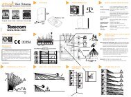
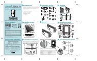
1 PHYSICAL<br />
2 ENVIRONMENTAL<br />
3 STANDARDS & APPROVALS<br />
Professional High Immunity PIR<br />
INSTALLATION INSTRUCTIONS<br />
40mm<br />
(1.6”)<br />
Detector Standard: Independently Certified to TS 50131-2-2 Grade 2<br />
Environmental Class II.<br />
System Standard: Suitable for use in a PD 6662/BS EN 50131-1 Grade<br />
2 system. Environmental Class II.<br />
EMC: Independently Certified to EN 50130-4 : 1996<br />
INS 252-4<br />
<strong>www</strong>.<strong>texe</strong>.<strong>com</strong><br />
Ask your distributor today for the Texe<strong>com</strong> full colour Product Guide.<br />
60mm<br />
(2.4”)<br />
112.25mm<br />
(4.4”)<br />
2.5mm (0.1”) ABS<br />
-35°C (-31°F) to +60°C (+140°F)<br />
150g (5oz) approx.<br />
-35°C (-31°F) to +55°C (+131°F)<br />
RF Immunity:<br />
No false alarms from 80MHz to 1GHz at 10V/m.<br />
Complies with BS EN 61000-4-3 : 2002.<br />
Electrostatic Discharge: No false alarms up to 8kV.<br />
Complies with BS EN 61000-4-2 : 1995.<br />
Fast Transient Immunity: No false alarms up to ±4kV.<br />
Complies with BS EN 61000-4-4 : 1995.<br />
High Energy<br />
No false alarms up to ±2kV.<br />
Transient Immunity: Complies with BS EN 61000-4-5 : 1995.<br />
Conducted RF<br />
No false alarms at 10Vrms.<br />
Susceptibility: Complies with BS EN 61000-4-6 : 1996.<br />
Conducted & Radiated Complies with EN 55022 Class B.<br />
Emissions:<br />
Product Identifier: IR<br />
QUALITY ASSURANCE<br />
4<br />
JP1<br />
✗<br />
LED OFF<br />
PULSE COUNT<br />
C e r t i f i c a t e N u m b e r : F M 3 5 2 8 5<br />
Made In England<br />
1<br />
JP1<br />
LED ON<br />
WARRANTY<br />
10 year replacement warranty.<br />
The Prestige IR is designed to detect the movement of an intruder and<br />
activate an alarm control panel. As the Prestige IR is not a <strong>com</strong>plete alarm<br />
system, but only a part thereof, Texe<strong>com</strong> cannot accept responsibility or liability<br />
for any damages whatsoever based on a claim that the Prestige IR failed to<br />
function correctly.<br />
Due to our policy of continuous improvement Texe<strong>com</strong> reserves the right to change<br />
specification without prior notice. All specifications are measured at 20ºC (68ºF).<br />
© 2003-2006 Texe<strong>com</strong> Ltd. Document Ref: PIR/EU/1.0-4<br />
The Prestige IR is protected by UK & International Registered Designs. Registered Design No’s: 3004997, 3004260,<br />
3004261 & 3008616. Prestige, CloakWise and PetWise are Trademarks of Texe<strong>com</strong> Ltd.<br />
DO NOT TOUCH<br />
✗<br />
EOL Resistor<br />
See Section 14<br />
2<br />
3<br />
0.3 - 3.0m/s<br />
1 - 10ft/s<br />
5 COVERAGE AND PICK-UP<br />
6 ANGLING THE DETECTOR<br />
7 MOUNTING HEIGHT AND<br />
SETTINGS<br />
8<br />
ALTERING COVERAGE AT 2m<br />
MOUNTING HEIGHT<br />
15m<br />
50’<br />
✓<br />
90º<br />
2m<br />
6'7"<br />
✓<br />
15m 50'<br />
2.5m/8’2”<br />
3.0m/9’10”<br />
2.0m/6’7”<br />
2m<br />
6'7"<br />
2m<br />
6'7"<br />
2m<br />
6'7"<br />
8m<br />
26'2"<br />
10m<br />
32'9"<br />
2m<br />
6'7"<br />
1.5m/4’11”<br />
2m<br />
6'7"<br />
15m<br />
50'<br />
15m<br />
50’<br />
4m<br />
13'1"<br />
15m<br />
50'
9 COVERAGE PATTERN<br />
Volumetric<br />
10 MOUNTING THE PRESTIGE IR<br />
For indoor use only<br />
11 MOUNTING THE PRESTIGE IR<br />
Mount on a stable surface<br />
12 WIRING<br />
Do not run cable parallel to mains wiring<br />
✗<br />
✓<br />
✗<br />
✓<br />
✓<br />
✓<br />
230V<br />
110V<br />
✗<br />
230V<br />
110V<br />
See Mounting Height Diagram (Section 7)<br />
13 CHOOSING A LOCATION<br />
Avoid <strong>com</strong>mon false alarm sources<br />
✗<br />
✗<br />
✗<br />
✗<br />
14 EOL RESISTOR JUMPER LINKS<br />
The jumper links JP3 and JP4 (see Section 4) are used to select resistances for<br />
End-of-Line (EOL) wiring applications.<br />
JP3 Selects the End-of-Line<br />
resistance. Equivalent to wiring<br />
a resistor of the selected value<br />
as shown.<br />
JP4 Selects the resistance<br />
across the alarm relay.<br />
Equivalent to wiring a resistor<br />
of the selected value as shown.<br />
EXAMPLES OF EOL JUMPER LINK USE<br />
TAMPER - JP3<br />
ALARM - JP4<br />
15 DETECTOR KNOCKOUTS<br />
✗<br />
✗<br />
✗<br />
✗<br />
If EOL wiring is not used, the headers should be left in the default (O/C) position.<br />
If the required resistance values are not available, leave the headers in the O/C position<br />
and wire in external resistors as normal.<br />
EOL Settings for Texe<strong>com</strong> Panels JP3 JP4<br />
Premier & Premier International 2k2 4k7Cexample<br />
Double Pole<br />
(jumper links not used)<br />
Dual End-of-Line<br />
(DEOL)<br />
16 CEILING MOUNT BRACKET<br />
1 2 3<br />
4<br />
✗<br />
5 8<br />
17 WALL MOUNT BRACKET<br />
6<br />
Seal all holes<br />
7<br />
✓<br />
1 2<br />
3 4 5<br />
INS 252-4