Overall dimensions - Castle Power Solutions
Overall dimensions - Castle Power Solutions
Overall dimensions - Castle Power Solutions

You also want an ePaper? Increase the reach of your titles
YUMPU automatically turns print PDFs into web optimized ePapers that Google loves.
Catalogue<br />
2009<br />
Super Solution<br />
Low voltage<br />
circuit breakers
The Challenges and Growth achieved by LG<br />
will continue with New Will of LS Industrial Systems.
New Name for LG Industrial Systems,<br />
New Take-off for LS Industrial Systems<br />
To advance to the next level,<br />
LG Industrial Systems is reborn as LS Industrial Systems.<br />
LS Industrial Systems will continue to lead the future<br />
of industrial electrics and automation by providing<br />
Total Solution, a core essential<br />
for competition in the 21 st century industrial era.
A brief company chronology<br />
Super Solution Molded Case Circuit Breakers<br />
2000’S<br />
1990’S<br />
Mar. 2005 <br />
Feb. 2004 <br />
Jan. 2004 <br />
Dec. 2001 <br />
Jun. 2001 <br />
Sept. 2000 <br />
Dec. 1999 <br />
Nov. 1999 <br />
Jun. 1997 <br />
Sept. 1995 <br />
Official Declaration of NEW Corporate Identification (LS)<br />
Signed investment agreement to build electricity/automation<br />
equipment factory in Usi City, Jangssu Province, China<br />
Opening U.A.E branch office<br />
Established trading company in Shanghai, China<br />
Unveiled a New Vision including Mid- and Long-Term Strategies<br />
Completion of <strong>Power</strong> Testing & Technology Institute<br />
Transfer of building equipment business to LG-OTIS<br />
Completion of electricity power plant in Vietnam<br />
Established joint venture in Vietnam<br />
LG Industrial Systems Co., Ltd. Goldstar Instrument & Electric Co., Ltd.<br />
and Goldstar Electric Machinery Co., Ltd. merged into one company.<br />
July. 1994 <br />
Completion of Dae-Ryun factory in China<br />
1980’S~<br />
1970’S<br />
July. 1984 <br />
July. 1974 <br />
LG Industrial Systems Co., Ltd. opened to public<br />
Established LG Industrial Systems Co., Ltd.<br />
1960’S~<br />
1950’S<br />
1 9 5 8 LGIS laid foundations for the Electric <strong>Power</strong> Industry<br />
~ 1 9 7 3 After Goldstar Co. was established in 1958, we started to<br />
produce WHM (Watt Hour Meter) units for the first time in<br />
Korea in 1964. We then proceeded to lay the foundation for<br />
the electric power and electronics industries, which were<br />
very important bases for industrial development of Korea.
R&D chronology<br />
2006 Developed Susol series MCCB & Contactor, TOR<br />
2002 Developed Meta-MEC 4 pole ELCB and Magnetic Contactor<br />
Developed UL MCCB up to 600A<br />
Developed the newest <strong>Power</strong> Equipment Diagnosis System<br />
Susol circuit breakers<br />
2001 Developed Meta-MEC series low AF MCCB and obtained KEMA<br />
certificate according to IEC60947 and marked CE<br />
Developed high voltage GIS 362kV, 63kA and 8000A<br />
2000 Developed Pro-MEC VCB and obtained international quality standard<br />
certificates (IEC 60056 & CESI)<br />
1999 Developed Meta-MEC series low AF Contactors & TOR and obtained<br />
KEMA certificate according to IEC60947 and marked CE<br />
Developed Korea's first DPR(Digital Protection Relay)<br />
Developed Meta-MEC series adjustable type MCCB and obtained CE<br />
certificate (IEC60947 & KEMA Mark)<br />
1998 Developed Meta-MEC series high AF MCCB & MS and obtained<br />
KEMA certificate according to IEC60947 and marked CE<br />
Developed Digital EMPR and obtained EMPR CE certificate<br />
META-MEC MCCB and ELCB<br />
(1996~ )<br />
MCB, BK type (1989~ )<br />
HiMEC MCCB and ELCB<br />
(1989~1998)<br />
1997 Obtained the CE certificate (IEC 60947, TUV certificate) on MCCB, MS<br />
1996 LGIS Cheongju Plant obtained the ISO14001<br />
1995 Developed Demand Controller<br />
Developed high-performance Hi-MEC series MCCB & ELCB<br />
1993 Obtained ISO9001<br />
Obtained ISO9002 for low voltage equipment<br />
Developed EMPR (Electronic Motor Protection Relay)<br />
Developed Korea's first GIMAC (Digital Integrated Meter)<br />
1992 Developed IMC (Intelligent Motor Controller)<br />
1990 Obtained U.S. ANSI Standard for vacuum circuit breakers<br />
1989 Developed Korea's first high-performance Hi-MEC series MCCB & ELCB<br />
1986 Broke the 10million units barrier in electric equipment<br />
Commenced the SCADA System Project<br />
Developed 154kV high-voltage GCB (Gas Circuit Breaker)<br />
Initiated the high-voltage GIS (Gas Insulated Switchgear) project<br />
1984 Obtained LR and KR certification for MCCB<br />
1977 Developed Earth Leakage Circuit Breakers<br />
1974 Developed Molded Case Circuit Breakers
Super Solution<br />
■Design for technical strong point: The Susol Design<br />
SuSol Series MCCB is available forworld best breaking capacity up to<br />
150kA, and MS is seal structure for hidden electricity Arc.<br />
SuSol product represents simultaneously simple and complicated<br />
design for using cut diamond motive to emphasis on the hardness of<br />
industrial product.<br />
And we applied the identity of product image by designing same concept<br />
MCCB and MS which is installed to cubicle.<br />
SuSol Series acquire the competitive power through getting the picking<br />
up GD product and wining IF Design Award.<br />
For power distribution<br />
▶ The highest breaking capacity<br />
▶ Optimum coordination technique (Cascading & discrimination)<br />
▶ <strong>Power</strong>ful engineering tools<br />
For protection of motor & its control device<br />
▶ Optimal overload protection<br />
▶ Guaranteed type-2 coordination between circuit breaker and<br />
contactor, relay<br />
For controlling and disconnecting circuits<br />
For extensive applications<br />
▶ Wide range of optimized auxiliaries and accessories
Global Leading Products<br />
Circuit breakers<br />
For protection of power distribution<br />
Circuit breakers<br />
For protection of motor &<br />
its control device<br />
Disconnecting switches<br />
For controlling and<br />
disconnecting circuits
Overview<br />
Susol TD and TS series<br />
Circuit breakers and Disconnecting switches<br />
Susol TD and TS circuit breakers provide<br />
superior performance in a compact<br />
package. They are used in cascade rated<br />
systems, allowing the use of lower<br />
interruption circuit breakers downstream,<br />
which lead to lower system cost.<br />
While meeting IEC60947-2 service and<br />
interrupting ratings, these breakers<br />
provide unmatched flexibility by employing<br />
a wide variety of trip units including fixed<br />
thermal & magnetic, adjustable thermalfixed<br />
magnetic, adjustable thermal<br />
adjustable magnetic, and electronic<br />
options.<br />
Susol TD circuit breaker is available in<br />
one frame size in ratings from 16 to 160<br />
amperes and TS circuit breakers are<br />
available in three frame sizes in ratings<br />
from 40 to 800 amperes and in interrupting<br />
capacities up to 150 kA at 415V AC.<br />
Standard calibration is at 40°C with<br />
optional 55°C factory calibration available<br />
for applications where higher ambient<br />
temperatures are encountered.<br />
8
Overview<br />
System overview<br />
<br />
<br />
<br />
<br />
<br />
Circuit breaker<br />
Plug-in base<br />
Insulation barrier<br />
Terminal cover (Short, Long)<br />
Connection terminals<br />
Motor operator<br />
Direct rotary handle<br />
Extended rotary handle<br />
Aux. handle<br />
Locking devices<br />
(Removable, Fixed)<br />
Mechanical interlock device<br />
Trip units<br />
Electrical auxiliaries<br />
Residual Current Devices<br />
<br />
<br />
<br />
<br />
<br />
<br />
<br />
<br />
<br />
<br />
<br />
<br />
9
Marking and configuration<br />
Rated frequency Standard Manufacturer Utilization category<br />
Symbol indicating<br />
suitability for isolation<br />
as defined by IEC 947-2<br />
10
Marking and configuration<br />
Model (Rating and breaking capacity)<br />
TS: Series<br />
250: Max. Ampere rating<br />
N: Normal (Standard)<br />
H: High<br />
L: Current limiting<br />
Standardized characteristics:<br />
Ui: Rated insulation voltage<br />
Uimp: Impulse withstand voltage<br />
Ue: Rated operational voltage<br />
Icu: Ultimate breaking capacity<br />
Ics: Service breaking capacity<br />
N<br />
-<br />
-<br />
H<br />
-<br />
-<br />
L<br />
-<br />
-<br />
160AF<br />
TD100N<br />
TD160N<br />
-<br />
TD100H<br />
TD160H<br />
-<br />
TD100L<br />
TD160L<br />
-<br />
250AF<br />
TS100N<br />
TS160N<br />
TS250N<br />
TS100H<br />
TS160H<br />
TS250H<br />
TS100L<br />
TS160L<br />
TS250L<br />
630AF<br />
TS400N<br />
TS630N<br />
-<br />
TS400H<br />
TS630H<br />
-<br />
TS400L<br />
TS630L<br />
-<br />
800AF<br />
TS800N<br />
-<br />
-<br />
TS800H<br />
-<br />
-<br />
TS800L<br />
-<br />
-<br />
N<br />
30kA(1P)<br />
50kA<br />
50kA<br />
65kA<br />
65kA<br />
H<br />
50kA(1P)<br />
85kA<br />
85kA<br />
85kA<br />
100kA<br />
L<br />
150kA<br />
150kA<br />
150kA<br />
150kA<br />
Product: Molded Case Circuit Breaker<br />
Upstream connections<br />
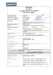
CB Test certificate by KEMA<br />
Ref. Certificate No.: NL-9937<br />
Standard No. IEC60947-2<br />
Fixing hole<br />
Certificate plate<br />
Indication of closed (I/ON) position<br />
Brand name<br />
Operating handle<br />
Indication of open (O/OFF) position<br />
Company logo<br />
"push to trip" button<br />
Rating of trip unit<br />
Trip unit<br />
Fixing hole<br />
Downstream connections<br />
11
Trip units<br />
On TS100 to TS800 circuit breakers, the thermal-magnetic and electronic trip units are interchangeable and may be<br />
rapidly fitted to the circuit breakers.<br />
It is therefore easy to change the protection of a given circuit following a modification in an installation. On TS400 and<br />
630 circuit breakers, the electronic trip units are interchangeable plug-in modules. Trip unit ETM offers a large number<br />
of protection settings.<br />
Each Trip devices has different types of protection depending on the associated trip unit:<br />
Standard protection<br />
Protection of networks supplied by line distribution<br />
Protection of long cables<br />
Protection of DC networks<br />
Protection of motor-starters<br />
Service connection circuit breaker (for special subscriber contracts)<br />
Susol TD100, TD160 circuit breakers may be equipped with either FTU or FMU.<br />
The trip units are not interchangeable types and can be supplied only after fixed with circuit breakers.<br />
MCCB frame type<br />
Rated current, In [A]<br />
Type of Thermal magnetic release Electronic release<br />
trip unit FTU FMU ATU MTU ETS ETM<br />
DSU<br />
TD100 Built in<br />
16, 20, 25, 32, 40, 16, 20, 25, 32, 40,<br />
50, 63, 80, 100 50, 63, 80, 100<br />
- - - - -<br />
TD160<br />
unit<br />
100, 125, 160 100, 125, 160 - - - - 160<br />
TS100<br />
40, 50, 63, 40, 50, 63,<br />
-<br />
1.6, 3.2, 6.3, 12,<br />
40, 80 - 100<br />
80, 100 80, 100 20, 32, 50, 63, 100<br />
TS160 Inter 100, 125, 160 100, 125, 160 100, 125, 160<br />
TS250<br />
changeable<br />
TS400<br />
trip unit<br />
Ampere ratings<br />
32, 50, 63,<br />
40, 80, 160 - 160<br />
100, 160<br />
125, 160, 200, 250 125, 160, 200, 250 125, 160, 200, 250 100, 160, 220 40, 80, 160, 250 - 250<br />
300, 400 300, 400 300, 400 320 160, 250, 400 160, 250, 400 400<br />
TS630 500, 630 500, 630 500, 630 500 160, 250, 400, 630 160, 250, 400, 630 630<br />
TS800 700, 800 800 800 630 630, 800 630, 800 800<br />
Types of trip units<br />
FTU<br />
FMU<br />
ATU<br />
MTU<br />
ETS<br />
ETM<br />
DSU<br />
Fixed thermal, Fixed magnetic<br />
Adjustable thermal, Fixed magnetic<br />
Adjustable thermal, Adjustable magnetic<br />
Magnetic only<br />
Electronic (LSI)<br />
Electronic (LSIG, Ammeter, Communication, Zone selective interlocking)<br />
Disconnecting switch<br />
12
Trip units<br />
FTU<br />
Fixed-thermal, fixed-magnetic<br />
TS250 FTU<br />
Im=2500A<br />
Ir<br />
Im<br />
Electronic<br />
trip unit<br />
FMU<br />
Adjustable-thermal, fixed-magnetic<br />
Thermal magnetic<br />
trip unit<br />
ATU<br />
Adjustable-thermal, adjustable-magnetic<br />
TS250 ATU<br />
0.9<br />
7 8<br />
Trip unit identification<br />
TS250<br />
FMU<br />
0.8<br />
1<br />
Ir<br />
Im<br />
6<br />
5<br />
9<br />
10<br />
MTU<br />
Magnetic only<br />
MCCB frame type<br />
Trip unit function<br />
TS250MTU<br />
Im<br />
1848 2112<br />
1584<br />
2376<br />
1320 2640<br />
220A<br />
3P<br />
DSU<br />
Disconnecting switch<br />
TS250 DSU<br />
3P<br />
ETS<br />
Electronic (LSI)<br />
FTU<br />
ATU<br />
ETM<br />
ETM<br />
Electronic (LSIG, multi-function unit)<br />
13
MCCBs for power distribution<br />
Electrical characteristics<br />
Frame size<br />
[AF]<br />
Rated current, In ♣<br />
[A]<br />
No. of poles<br />
Rated operational AC [V]<br />
voltage, Ue DC [V]<br />
Rated impulse withstand voltage, Uimp<br />
[kV]<br />
Rated insulation voltage, Ui [V]<br />
Rated ultimate short-circuit breaking capacity, Icu<br />
AC 50/60Hz<br />
220/240V [kA]<br />
380/415V [kA]<br />
440/460V [kA]<br />
480/500V [kA]<br />
660/690V [kA]<br />
DC<br />
250V<br />
[kA]<br />
500V(2poles in series) [kA]<br />
Rated service breaking capacity, Ics<br />
[%Icu]<br />
Rated short-circuit making capacity Icm<br />
AC 50/60Hz<br />
220/240V [kA]<br />
380/415V [kA]<br />
440/460V [kA]<br />
480/500V [kA]<br />
660/690V [kA]<br />
Category of utilization<br />
Isolation behavior<br />
Trip unit (release)<br />
Thermal-Magnetic<br />
●fixed-thermal, fixed-magnetic<br />
FTU<br />
●adjustable-thermal, fixed-magnetic<br />
FMU<br />
●adjustable-thermal, adjustable-magnetic ATU<br />
●magnetic only<br />
Electronic<br />
●LSI<br />
●LSI<br />
Option Earth-fault protection, Ig<br />
Zone selective interlocking, ZSI<br />
Ammeter<br />
Communication<br />
MTU ★★★<br />
ETS ★★★<br />
ETM ★★★<br />
Earth-leakage protection module ★★★★<br />
Connection fixed front-connection<br />
rear-connection<br />
plug-in front-connection<br />
rear-connection<br />
Mechanical life<br />
[operations]<br />
Electrical life @ 415 V AC<br />
[operations]<br />
Basic <strong>dimensions</strong>, W×H×D 1-pole [mm]<br />
(front connection) 3-pole [mm]<br />
4-pole<br />
[mm]<br />
Weight 1-pole [kg]<br />
(front connection) 3-pole [kg]<br />
4-pole<br />
[kg]<br />
Reference standard<br />
14<br />
TD100 TD160 TS100<br />
100 160 100<br />
1P: 16, 20, 25, 32, 40, 50,<br />
16, 20, 25, 32, 40,<br />
63, 80, 100, 125, 160<br />
50, 63, 80, 100<br />
2, 3P: 100, 125, 160<br />
40, 50, 63, 80, 100<br />
2 ★ , 3, 4 1, 2 ★ , 3, 4 2 ★ , 3, 4<br />
690 240(1P), 690 690<br />
500 250(1P), 500 500<br />
8 8 8<br />
750 750 750<br />
N H L N H L N H L<br />
30(1P) 50(1P)<br />
85 100 200<br />
85 100<br />
200 100 120 200<br />
50 85 150 50 85 150 50 85 150<br />
50 70 130 50 70 130 50 70 130<br />
30 50 65 30 50 65 42 65 85<br />
5 8 10 5 8 10 10 15 20<br />
16(1P) 25(1P)<br />
42 65 100<br />
42 65<br />
100 50 85 100<br />
42 65 100 42 65 100 50 85 100<br />
100% 100% 100% 100% 100% 100% 100% 100% 100%<br />
105(1P) 105(1P)<br />
187 220 440<br />
187 220<br />
440 220 264 440<br />
105 187 330 105 187 330 105 187 330<br />
105 154 286 105 154 286 105 154 286<br />
63 105 143 63 105 143 88 143 187<br />
8 14 17 8 14 17 17 30 40<br />
A A A<br />
● ● ●<br />
● ● ●<br />
● ● ★★★★★ ●<br />
- - -<br />
- - ●<br />
- - ●<br />
- - -<br />
- - -<br />
- - -<br />
- - -<br />
- - -<br />
- - -<br />
● ● ●<br />
● ● ★★★★★ ●<br />
● ● ★★★★★ ●<br />
● ● ★★★★★ ●<br />
25000 25000 25000<br />
10000 10000 10000<br />
- 35×140×86 -<br />
90×140×86 90×140×86 105×160×86<br />
120×140×86 120×140×86 140×160×86<br />
- 0.57 -<br />
1.5 1.5 2<br />
1.8 1.8 2.6<br />
IEC60947-2 IEC60947-2 IEC60947-2<br />
♣<br />
Applicable to MCCBs equipped with FTU, FMU, ATU<br />
★<br />
2 pole MCCB in 3pole frame size<br />
★★<br />
700A only available for TS800FTU<br />
★★★<br />
Available for 3pole circuit breakers<br />
★★★★<br />
Under development<br />
★★★★★<br />
Not applicable to 1pole
TS160 TS250 TS400 TS630<br />
TS800<br />
160 250 400 630 800<br />
(100) ※ , 125, 160 125, 160, 200, 250 300, 400 500, 630 700 ★★ , 800<br />
2 ★ , 3, 4 2 ★ , 3, 4 2 ★ , 3, 4 2 ★ , 3, 4 2 ★ , 3, 4<br />
690 690 690 690 690<br />
500 500 500 500 500<br />
8 8 8 8 8<br />
750 750 750 750 750<br />
N H L N H L N H L N H L N H L<br />
100 120 200 100 120 200 100 120 200 100 120 200 100 120 200<br />
50 85 150 50 85 150 65 85 150 65 85 150 65 100 150<br />
50 70 130 50 70 130 65 85 130 65 85 130 65 100 130<br />
42 65 85 42 65 85 42 65 85 42 65 85 42 85 100<br />
10 15 20 10 15 20 10 20 35 10 20 35 10 20 35<br />
50 85 100 50 85 100 50 85 100 50 85 100 50 85 100<br />
50 85 100 50 85 100 50 85 100 50 85 100 50 85 100<br />
100% 100% 100% 100% 100% 100% 100% 100% 100% 100% 100% 100% 100% 100% 100%<br />
220 264 440 220 264 440 220 264 440 220 264 440 220 264 440<br />
105 187 330 105 187 330 143 187 330 143 187 330 143 220 330<br />
105 154 286 105 154 286 143 187 286 143 187 286 143 220 286<br />
88 143 187 88 143 187 88 143 187 88 143 187 88 187 220<br />
17 30 40 17 30 40 17 40 74 17 40 74 17 40 74<br />
A A A A A<br />
● ● ● ● ●<br />
● ● ● ● ●<br />
● ● ● ● ●<br />
● ● ● ● ●<br />
● ● ● ● ●<br />
● ● ● ● ●<br />
- - ● ● ●<br />
- - ● ● ●<br />
- - ● ● ●<br />
- - ● ● ●<br />
- - ● ● ●<br />
- - ● ● ●<br />
● ● ● ● ●<br />
● ● ● ● ●<br />
● ● ● ● ●<br />
● ● ● ● ●<br />
25000 25000 20000 20000 10000<br />
10000 10000 6000 6000 3000<br />
- - - - -<br />
105×160×86 105×160×86 140×260×110 140×260×110 210×320×135<br />
140×160×86 140×160×86 186.5×260×110 186.5×260×110 280×320×135<br />
- - - - -<br />
2 2 5.4 5.4 15.1<br />
2.6 2.6 7.2 7.2 19.6<br />
IEC60947-2 IEC60947-2 IEC60947-2 IEC60947-2 IEC60947-2<br />
1. The breakers with electronic trip units are available only at 3-pole version. (Only for AC supply)<br />
※ The trip unit ATU is available from 125A<br />
15
MCCBs for power distribution<br />
Thermal magnetic trip units<br />
The new series of Susol TD & TS series molded case circuit breakers can be fitted with thermal magnetic trip units and<br />
are used in protection of AC and DC networks with a range of use from 16A to 800A. There are two kinds of trip units<br />
according to way of installation as follows.<br />
Built-in trip units for TD series upto 160A<br />
Interchangeable trip units for TS series upto 800A<br />
Function<br />
Protection of power distribution<br />
Overload protection: Thermal protection with a fixed or adjustable threshold<br />
Short-circuit protection: Magnetic protection with a fixed or adjustable pick-up<br />
Protection of the fourth pole<br />
4P3T type (neutral unprotected)<br />
4P4T type 50% (neutral protection at 0.5×In)<br />
4P4T type 100% (neutral protection at 1×In)<br />
Operation<br />
Trip bar<br />
ATU<br />
Thermal magnetic types<br />
Time-Delay operation<br />
An overcurrent heats and warps the bimetal to actuate the trip bar by<br />
the bimetal characteristic.<br />
Instantaneous operation<br />
If the overcurrent is excessive, the armature is attracted and the trip bar<br />
actuated by electromagnetic force.<br />
Bimetal<br />
Armature<br />
Ratings<br />
Ratings(A)<br />
at 40℃<br />
TD100<br />
TD160<br />
TS100<br />
TS160<br />
TS250<br />
TS400<br />
TS630<br />
TS800<br />
In<br />
Thermal magnetic trip units(FTU/FMU/ATU) TD100 to TS800<br />
16 20 25 32 40 50 63 80 100 125 160 200 250 300 400 500 630 800<br />
● ● ● ● ● ● ● ● ● - - - - - - - - -<br />
- - - - - - - - ● ● ● - - - - - - -<br />
- - - - ● ● ● ● ● - - - - - - - - -<br />
- - - - - - - - ● ● ● - - - - - - -<br />
- - - - - - - - - ● ● ● ● - - - - -<br />
- - - - - - - - - - - - - ● ● - - -<br />
- - - - - - - - - - - - - - - ● ● -<br />
- - - - - - - - - - - - - - - - - ●<br />
Note) Rated current 700A is available for TS800FTU.<br />
16
MCCBs for power distribution<br />
Thermal magnetic trip units<br />
Overview<br />
Characteristics<br />
Fixed thermal, fixed magnetic trip units<br />
FTU<br />
Fixed thermal<br />
16A ... 800A rated currents<br />
Fixed magnetic<br />
400A ... 8000A tripping currents<br />
Applicable to TD100 ... TS800 frames<br />
TS250 FTU<br />
Ir<br />
Im<br />
Im=2500A<br />
Adjustable thermal, fixed magnetic trip units<br />
FMU<br />
Adjustable thermal<br />
16A ... 800A rated currents<br />
Adjustable : 0.8~1×In<br />
Fixed magnetic<br />
400A ... 8000A tripping currents<br />
Applicable to TD100 ... TS800 frames<br />
Adjustable thermal, adjustable magnetic trip units<br />
ATU<br />
Adjustable thermal<br />
100A ... 800A rated currents<br />
Adjustable : 0.8~1×In<br />
Adjustable magnetic<br />
500A ... 8000A tripping currents<br />
Adjustable : 5~10×In<br />
Applicable to TS160 ... TS800 frames<br />
TS250 ATU<br />
0.8<br />
0.9<br />
1<br />
Ir<br />
Im<br />
7 8<br />
6<br />
9<br />
5 10<br />
17
MCCBs for power distribution<br />
Electronic trip units (Standard type)<br />
The new series of Susol TS series molded case circuit breakers for AC networks can be equipped with ETS23,<br />
ETS33 and ETS43. The trip units can be fitted with three (3) pole TS100 to TS800.<br />
The wide range of adjustments makes the trip units particularly suitable in all distribution applications where<br />
reliability and trip precision are required.<br />
Function<br />
Protection of power distribution<br />
Overload protection<br />
Short-circuit protection<br />
Ratings<br />
Trip units<br />
ETS23 ETS33 ETS43<br />
Rated 40<br />
current, 80<br />
In (A) 160<br />
250<br />
400<br />
630<br />
800<br />
Applicable to<br />
● ● ● - - -<br />
● ● ● - - -<br />
- ● ● ● ● -<br />
- - ● ● ● -<br />
- - - ● ● -<br />
- - - - ● ●<br />
- - - - - ●<br />
TS100 N/H/L TS160 N/H/L TS250 N/H/L TS400 N/H/L TS630 N/H/L TS800 N/H/L<br />
Current setting, Ir(A)<br />
ETS<br />
ETS23 for TS100N/H/L<br />
ETS23 for TS160N/H/L<br />
ETS23 for TS250N/H/L<br />
ETS33 for TS400N/H/L<br />
ETS33 for TS630N/H/L<br />
ETS43 for TS800N/H/L<br />
16 32 40 64 80 100 160 250 320 400 630 800<br />
Setting values<br />
Overload protection (long time)<br />
Setting current (A), Ir<br />
Tripping time (s)<br />
0.4, 0.45, 0.5, 0.55, 0.6, 0.65, 0.7, 0.75, 0.8, 0.85, 0.9, 0.95, 1.0×In,<br />
13 setting<br />
Fixed at 6×Ir , tolerance±20%<br />
Short-circuit protection (short time)<br />
Tripping threshold (A), 1.5, 2, 3, 4, 5, 6, 7, 8, 10×Ir<br />
(Isd) 9 settings, tolerance ±15%<br />
Time delay setting time (ms) 50 100 200 300<br />
(tsd) operation time (ms) 30t≤70 70t≤140 140t≤240 240t≤350<br />
4 settings<br />
Short circuit protection (Instantaneous)<br />
Tripping threshold (A), Ii<br />
Fixed at 11×In<br />
18
MCCBs for power distribution<br />
1 Adjustable rated current<br />
setting (Ir)<br />
2 Adjustable short time<br />
delay current setting (Isd)<br />
3 Adjustable time delay<br />
setting (tsd)<br />
4 Alarm LED<br />
90% Ir: ON,<br />
105% Ir or more: ON-OFF<br />
5 Test connector<br />
ETS23 for TS100/TS160/TS250<br />
1 2 4 3<br />
5<br />
t<br />
1<br />
ETS33 for TS400/TS630<br />
1 2 4<br />
tsd<br />
2<br />
3<br />
5<br />
.7<br />
.6 .8<br />
.5<br />
.9<br />
.4 1.0<br />
+ -<br />
TEST<br />
5<br />
4 6<br />
3<br />
7<br />
2<br />
8<br />
1.5 10<br />
.3<br />
.2<br />
.1<br />
.05 .3<br />
tsd<br />
alarm<br />
90%<br />
105%<br />
ETS33<br />
In 630A<br />
tr<br />
tsd<br />
Ir Isd Ii<br />
Ir Isd Ii I<br />
3<br />
ETS43 for TS800<br />
1 2 4<br />
.6<br />
.5<br />
.4<br />
.7<br />
.8<br />
.9<br />
1.0<br />
4<br />
3<br />
2<br />
1.5<br />
5<br />
6<br />
7<br />
8<br />
10<br />
alarm<br />
90%<br />
105%<br />
ETS43<br />
.3<br />
5<br />
+ -<br />
TEST<br />
.2<br />
.1<br />
.05 .3<br />
tsd<br />
In 800A<br />
3<br />
19
MCCBs for power distribution<br />
Electronic trip units (Multi-functional type)<br />
The new series of Susol TS series molded case circuit breakers for AC networks can be equipped with ETM33 and<br />
ETM43. The trip units can be fitted with three (3) pole TS400, TS630 and TS800.<br />
The more wide range of adjustments makes the trip units particularly suitable in all distribution applications where<br />
reliability and trip precision are required.<br />
Function<br />
Protection of power distribution<br />
Overload, Short-circuit protection, Instantaneous protection, Earth fault protection<br />
Ammeter<br />
Zone selective interlocking (ZSI)<br />
Communication (RS485-Modbus/RTU)<br />
Ratings<br />
Rated current, In(A)<br />
Rated current<br />
Trip unit<br />
In (A) ETM33 ETM43<br />
160 ● ● -<br />
250 ● ● ●<br />
400 ● ● ●<br />
630 - ● ●<br />
800 - - ●<br />
Circuit breakers TS400 N/H/L TS630 N/H/L TS800 N/H/L<br />
Setting values<br />
Overload protection (long time)<br />
Setting current (A), Ir<br />
Tripping time (s) at 6× Ir<br />
Adjustable 0.4 ~ 1.0×In, 30 settings<br />
Adjustable 2, 4, 6, 8,12 5 settings, tolerance±20%<br />
Short-circuit protection (short time)<br />
Tripping threshold (A), Isd Adjustable 1.5, 2, 3, 4, 5, 6, 7, 8, 10×Ir, 9 settings, tolerance ±15%<br />
Time delay setting time (ms) 50 100 200 300 4 settings<br />
(tsd) operation time (ms) 30t≤70 70t≤140 140t≤240 240t≤350 I 2 t is off<br />
Short-circuit protection (instantaneous)<br />
Tripping threshold (A), Ii<br />
Adjustable 1.5, 2, 4, 5, 6, 8, 10, 11×In, 9 settings<br />
Indication of tripping reason<br />
LED indication<br />
Ir, Isd, Ii, (Ig)<br />
Option for TS400ETM to TS800ETM<br />
Ammeter (A)<br />
Maximum load phase current and R,S,T,N phase current<br />
Adjustable tripping threshold (A), 0.2~1×In, 9 setting<br />
Earth fault protection (E) setting time (ms) 100 200 300 400 4 settings<br />
operation time (ms) 60t≤140 140t≤230 230t≤350 350t≤500 I 2 t is off<br />
Communication (C)<br />
ZSI (Z)<br />
Setting, R, S, T, N phase current, tripping reason<br />
ZSI input and output signal<br />
20
MCCBs for power distribution<br />
1 Adjustable rated current<br />
setting (Ir)<br />
ETM33 for TS400/TS630<br />
2 Adjustable long time<br />
setting (tr)<br />
1 3 6 13<br />
3 Adjustable short time<br />
current setting (Isd)<br />
4 Adjustable time delay<br />
setting (tsd)<br />
9<br />
5 Adjustable instantaneous<br />
current setting (Ii)<br />
6 Adjustable earth fault<br />
current setting (Ig)<br />
7 Adjustable earth fault<br />
delay setting (tg)<br />
8 Indication LED<br />
9 TR (trip reason) button<br />
10 Display LCD (Ammeter)<br />
11 Battery<br />
12 Test connector<br />
13 Alarm LED<br />
ETM43 for TS800<br />
12 2 5 4 7 8<br />
Ir = 625A<br />
It = 540A<br />
11<br />
10<br />
1 3 6 13<br />
t<br />
9<br />
tr<br />
Isd<br />
Ir = 760A<br />
It = 695A<br />
11<br />
10<br />
lg<br />
OFF<br />
ON<br />
tsd<br />
OFF<br />
ON<br />
ta<br />
li<br />
12 2 5 4 7 8<br />
21
MCCBs for motor protection<br />
Electrical characteristics<br />
Frame size<br />
[AF]<br />
Rated current, In<br />
[A]<br />
No. of poles<br />
Rated operational AC [V]<br />
voltage, Ue DC [V]<br />
Rated impulse withstand voltage, Uimp<br />
[kV]<br />
Rated insulation voltage, Ui<br />
[V]<br />
Rated ultimate short-circuit breaking capacity, Icu<br />
AC 50/60Hz 220/240V [kA]<br />
380/415V [kA]<br />
440/460V [kA]<br />
480/500V [kA]<br />
660/690V [kA]<br />
Rated service breaking capacity, Ics [%Icu]<br />
Rated short-circuit making capacity, Icm<br />
AC 50/60Hz 220/240V [kA]<br />
380/415V [kA]<br />
440/460V [kA]<br />
480/500V [kA]<br />
660/690V [kA]<br />
Category of utilization<br />
Isolation behavior<br />
Trip unit (release)<br />
●magnetic only<br />
MTU<br />
Connection fixed front-connection<br />
rear-connection<br />
plug-in front-connection<br />
rear-connection<br />
Mechanical life<br />
[operations]<br />
Electrical life @415 V AC<br />
[operations]<br />
Basic <strong>dimensions</strong>, W×H×D<br />
3-pole<br />
[mm]<br />
(front connection)<br />
Weight<br />
3-pole<br />
[kg]<br />
(front connection)<br />
Reference standard<br />
TS100 TS160 TS250<br />
100 160 250<br />
1.6, 3.2, 6.3, 12, 20, 32, 50, 63,<br />
100, 160, 220<br />
32, 50, 63, 100 100, 160<br />
3 3 3<br />
690 690 690<br />
500 500 500<br />
8 8 8<br />
750 750 750<br />
N H L N H L N H L<br />
100 120 200 100 120 200 100 120 200<br />
50 85 150 50 85 150 50 85 150<br />
50 70 130 50 70 130 50 70 130<br />
42 65 85 42 65 85 42 65 85<br />
10 15 20 10 15 20 10 15 20<br />
100% 100% 100% 100% 100% 100% 100% 100% 100%<br />
220 264 440 220 264 440 220 264 440<br />
105 187 330 105 187 330 105 187 330<br />
105 154 286 105 154 286 105 154 286<br />
88 143 187 88 143 187 88 143 187<br />
17 30 40 17 30 40 17 30 40<br />
A A A<br />
● ● ●<br />
● ● ●<br />
● ● ●<br />
● ● ●<br />
● ● ●<br />
● ● ●<br />
25000 25000 25000<br />
10000 10000 10000<br />
105×160×86 105×160×86 105×160×86<br />
2 2 2<br />
IEC60947-2 IEC60947-2 IEC60947-2<br />
22
MCCBs for motor protection<br />
TS400 TS630 TS800<br />
400 630 800<br />
320 500 630<br />
3 3 3<br />
690 690 690<br />
500 500 500<br />
8 8 8<br />
750 750 750<br />
N H L N H L N H L<br />
100 120 200 100 120 200 100 120 200<br />
65 85 150 65 85 150 65 100 150<br />
65 85 130 65 85 130 65 100 130<br />
42 65 85 42 65 85 42 85 100<br />
10 20 35 10 20 35 10 20 35<br />
100% 100% 100% 100% 100% 100% 100% 100% 100%<br />
220 264 440 220 264 440 220 264 440<br />
143 187 330 143 187 330 143 220 330<br />
143 187 286 143 187 286 143 220 286<br />
88 143 187 88 143 187 88 187 220<br />
17 40 74 17 40 74 17 40 74<br />
A A A<br />
● ● ●<br />
● ● ●<br />
● ● ●<br />
● ● ●<br />
● ● ●<br />
● ● ●<br />
20000 20000 10000<br />
6000 6000 3000<br />
140×260×110 140×260×110 210×320×135<br />
5.4 5.4 15.1<br />
IEC60947-2 IEC60947-2 IEC60947-2<br />
23
MCCBs for motor protection<br />
Magnetic only trip unit<br />
MTU for TS100, TS160, TS250, TS400, TS630, TS800<br />
L1<br />
L2<br />
L3<br />
1 3 5<br />
2 4 6<br />
1 3 5<br />
2 4 6<br />
Bre<br />
Con<br />
For the protection of motors from 1.6 to 250kW(400V), TS100 to<br />
TS800 circuit Breakers must be equipped with a special trip unit<br />
MTU adjustable thresholds.<br />
This assembly ensures: Short-circuit protection (magnetic trip unit<br />
with adjustable thresholds); Suitability for isolation. For the TS100<br />
to TS800 circuit breakers, trip unit MTU is interchangeable.<br />
The circuit breakers presented here: Provide protection against<br />
short-circuits; Are suitable for isolation as defined by IEC60947-2<br />
standard.<br />
O<br />
T1<br />
T2<br />
T3<br />
M<br />
Motor<br />
Magnetic only<br />
release<br />
Configuration<br />
Trip unit identification<br />
Trip unit rating, In<br />
and reference temperature<br />
Magnetic setting for short-circuit<br />
protection<br />
Catalogue numbering system<br />
TS250<br />
MTU<br />
Magnetic only release<br />
MCCB frame type<br />
- TS100: TS100N, TS100H, TS100L<br />
- TS160: TS160N, TS160H, TS160L<br />
- TS250: TS250N, TS250H, TS250L<br />
- TS400: TS400N, TS400H, TS400L<br />
- TS630: TS630N, TS630H, TS630L<br />
- TS800: TS800N, TS800H, TS800L<br />
24
MCCBs for motor protection<br />
Rating(A)<br />
N / H / L<br />
In<br />
TS100<br />
TS160<br />
TS250<br />
TS400<br />
TS630<br />
TS800<br />
Characteristics<br />
Magnetic trip units(MTU)<br />
TS100 to TS800<br />
1.6 3.2 6.3 12 20 32 50 63 100 160 220 320 500 630<br />
● ● ● ● ● ● ● ● ● - - - - -<br />
- - - - - ● ● ● ● ● - - - -<br />
- - - - - - - - ● ● ● - - -<br />
- - - - - - - - - - - ● - -<br />
- - - - - - - - - - - - ● -<br />
- - - - - - - - - - - - - ●<br />
Short - circuit protection(magnetic)<br />
Pick - up Im setting<br />
6..12×In (6 Point)<br />
Setting details<br />
MTU In 6×In .. .. .. .. 12×In<br />
1.6 10 12 14 16 18 20<br />
3.2 20 24 28 32 36 40<br />
6.3 40 48 56 64 72 80<br />
12 70 84 98 112 126 140<br />
20 120 144 168 192 216 240<br />
32 190 228 266 304 342 380<br />
50 300 360 420 480 540 600<br />
63 400 480 560 640 720 800<br />
MTU In 6×In .. .. .. .. 12×In<br />
100 600 720 840 960 1080 1200<br />
160 960 1152 1344 1536 1728 1920<br />
220 1320 1584 1848 2112 2376 2640<br />
320 1920 2304 2688 3072 3456 3840<br />
500 3000 3600 4200 4800 5400 6000<br />
630 3780 4536 5292 6048 6804 7560<br />
TS100MTU<br />
- Adjustable magnetic only unit<br />
TS100MTU<br />
Im<br />
560 640<br />
480<br />
400<br />
720<br />
800<br />
63A<br />
3P<br />
TS160MTU<br />
- Adjustable magnetic only unit<br />
TS160MTU<br />
Im<br />
1344 1536<br />
1152<br />
1728<br />
960 1920<br />
160A<br />
3P<br />
TS250MTU<br />
- Adjustable magnetic only unit<br />
TS250MTU<br />
Im<br />
1848 2112<br />
1584<br />
2376<br />
1320 2640<br />
220A<br />
3P<br />
t<br />
Im = 6...12×In<br />
14 16<br />
TS400 MTU, TS630MTU, TS800MTU<br />
- Adjustable magnetic only unit<br />
12<br />
10<br />
18<br />
20<br />
TS630MTU<br />
4600 5400<br />
3800<br />
6200<br />
500A<br />
Im<br />
3000<br />
7000<br />
0 Im<br />
I<br />
25
Switch-Disconnectors<br />
Electrical characteristics<br />
TD series<br />
Frame size<br />
[AF]<br />
Conventional thermal current, Ith [A]<br />
No. of poles<br />
Rated operational voltage, AC [V]<br />
Ue DC [V]<br />
Rated operational current, Ie<br />
Rated impulse withstand voltage,Uimp<br />
[kV]<br />
Rated insulation voltage, Ui<br />
[V]<br />
Rated short-circuit making capacity, Icm<br />
[kA peak]<br />
Rated short-time 1s [A rms]<br />
withstand current, Icw 3s [A rms]<br />
20s<br />
[A rms]<br />
Isolation behavior<br />
Trip unit (release)<br />
●disconnector unit<br />
DSU<br />
Connection fixed front-connection<br />
rear-connection<br />
plug-in front-connection<br />
rear-connection<br />
Mechanical life<br />
[operations]<br />
Electrical life @415 V AC<br />
[operations]<br />
Basic <strong>dimensions</strong>, W×H×D 3-pole [mm]<br />
(front connection) 4-pole [mm]<br />
Weight 3-pole [kg]<br />
(front connection) 4-pole [kg]<br />
Reference standard<br />
TD160NA TS100NA TS160NA<br />
160 100 160<br />
160 100 160<br />
2, 3, 4 2, 3, 4 2, 3, 4<br />
690 690 690<br />
500 500 500<br />
160 100 160<br />
8 8 8<br />
750 750 750<br />
3.1 2.8 3.6<br />
2200 2000 2500<br />
2200 2000 2500<br />
960 690 960<br />
● ● ●<br />
● ● ●<br />
● ● ●<br />
● ● ●<br />
● ● ●<br />
● ● ●<br />
25000 25000 25000<br />
10000 10000 10000<br />
90×140×86 105×160×86 105×160×86<br />
120×140×86 140×160×86 140×160×86<br />
1.5 2 2<br />
1.8 2.6 2.6<br />
IEC60947-3 IEC60947-3 IEC60947-3<br />
The switch-disconnectors are different from the circuit-breakers in the absence of the<br />
conventional protection unit. They keep the overall <strong>dimensions</strong>, connection systems and<br />
accessories unchanged from the corresponding circuit-breakers. Installation standards<br />
require upstream protection. However, thanks to their high-set magnetic release, TD160 ...<br />
TS800 DSU are self protected.<br />
26
Switch-Disconnectors<br />
TS series<br />
TS250NA TS400NA TS630NA<br />
TS800NA<br />
250 400 630 800<br />
250 400 630 800<br />
2, 3, 4 2, 3, 4 2, 3, 4 2, 3, 4<br />
690 690 690 690<br />
500 500 500 500<br />
250 400 630 800<br />
8 8 8 8<br />
750 750 750 750<br />
4.9 7.1 8.5 12<br />
3500 5000 6300 8000<br />
3500 5000 6300 8000<br />
1350 1930 2320 2560<br />
● ● ● ●<br />
● ● ● ●<br />
● ● ● ●<br />
● ● ● ●<br />
● ● ● ●<br />
● ● ● ●<br />
25000 20000 20000 10000<br />
10000 6000 6000 3000<br />
105×160×86 140×260×110 140×260×110 210×320×135<br />
140×160×86 186.5×260×110 186.5×260×110 280×320×135<br />
2 5.4 5.4 15.1<br />
2.6 7.2 7.2 19.6<br />
IEC60947-3 IEC60947-3 IEC60947-3 IEC60947-3<br />
Trip unit identification<br />
27
Accessories<br />
Electrical auxiliaries<br />
Auxiliary switch (AX)<br />
Auxiliary switch is for applications requiring remote “ON” and “OFF” indication.<br />
Each switch contains two contacts having a common connection.<br />
One is open and the other closed when the circuit breaker is open, and vice-versa.<br />
AX<br />
AL<br />
Alarm switch (AL)<br />
Alarm switches offer provisions for immediate audio or visual indication of a tripped breaker due to<br />
overload, short circuit, shunt trip, or undervoltage release conditions.<br />
They are particularly useful in automated plants where operators must be signaled about changes<br />
in the electrical distribution system. This switch features a closed contact when the circuit breaker<br />
is tripped automatically. In other words, this switch does not function when the breaker is operated<br />
manually. Its contact is open when the circuit breaker is reset.<br />
Fault alarm switch (FAL)<br />
FAL Indicates that the breaker has tripped due to overload or short circuit.<br />
And, it can be applied to only circuit breakers with electronic trip units.<br />
Undervoltage release, UVT<br />
The undervoltage release automatically opens a circuit breaker when voltage drops to a value<br />
ranging between 35% to 70% of the line voltage. The operation is instantaneous, and after tripping,<br />
the circuit breaker cannot be re-closed again until the voltage returns to 85% of line voltage.<br />
Continuously energized, the undervoltage release must be operating before the circuit breaker can<br />
be closed. The undervoltage release can be easily installed in the left accessory compartment of<br />
the Susol TD and TS circuit-breakers.<br />
UVT<br />
Range of tripping voltage: 0.35 ~ 0.7Vn<br />
MCCB making is possible voltage: 0.85Vn (exceed)<br />
Frequency (only AC): 45Hz ~ 65Hz<br />
Shunt release, SHT<br />
The shunt release opens the mechanism in response to an externally applied voltage signal. The<br />
releases include coil clearing contacts that automatically clear the signal circuit when the mechanism has tripped.<br />
The shunt release can be installed in the left accessory compartment of the Susol TD & TS circuit-breakers.<br />
Range of operational voltage: 0.7 ~ 1.1Vn<br />
Frequency (only AC): 45Hz ~ 65Hz<br />
TD160 TS250 TS630 TS800<br />
SHT<br />
AL<br />
AX AX<br />
AX<br />
AL<br />
*FAL<br />
AX<br />
SHT/<br />
UVT<br />
SHT/<br />
AX AX AX<br />
AL<br />
AX AX AX<br />
AL AL<br />
UVT<br />
*FAL<br />
*FAL<br />
SHT/<br />
UVT<br />
SHT/<br />
UVT<br />
28
Accessories<br />
Rotary handles<br />
The rotary handle operating mechanism is available in either the direct version or in the extended<br />
version on the compartment door.<br />
It is always fitted with a compartment door lock and on a request it can be supplied with a key lock<br />
in the open position.<br />
Direct rotary handles<br />
Direct rotary handles<br />
MCCB<br />
TD100,TD160<br />
TS100,TS160,TS250<br />
TS400,TS630<br />
TS800<br />
Rotary handle<br />
DH1<br />
DH2<br />
DH3<br />
DH4<br />
Direct rotary handles with a key lock<br />
MCCB Padlockable device Lock function<br />
TD100, TD160<br />
TS100, TS160, TS250<br />
TS400, TS630<br />
TS800<br />
DHK1<br />
DHK2<br />
DHK3<br />
DHK4<br />
Lock in On or Off position<br />
Direct rotary handles<br />
with a key lock<br />
Extended rotary handles<br />
Extended rotary handles<br />
MCCB<br />
TD100,TD160<br />
TS100,TS160,TS250<br />
TS400,TS630<br />
TS800<br />
Padlockable device<br />
EH1<br />
EH2<br />
EH3<br />
EH4<br />
Degree of protections<br />
Type<br />
Degree of protection<br />
IP<br />
Circuit breaker with<br />
cover frame and<br />
rotary direct handle<br />
Circuit breaker with cover frame and<br />
rotary direct handle<br />
The access probe of 1.0mm diameter<br />
shall not penetrate.<br />
IP40<br />
Circuit breaker with<br />
cover frame and<br />
rotary extended handle<br />
Circuit breaker with cover frame and<br />
rotary extended handle<br />
Totally protected<br />
against ingress of<br />
dust and water jets from any direction<br />
IP65<br />
29
Accessories<br />
Locking devices<br />
Removable locking device<br />
Removable locking device is available for all TD & TS circuit breakers.<br />
The locking device is designed to be easily attached to the circuit-breaker.<br />
5~8<br />
This device allows the handle to be locked in the “OFF” position.<br />
Locking in the OFF position guarantee isolation according to IEC 60947-2.<br />
The locking device for the toggle handle can be installed in 3-pole and 4-pole circuit-breakers.<br />
Maximum three (3) padlocks with shackle diameters ranging from 5 to 8mm may be used.<br />
(Padlocks are not supplied)<br />
30<br />
Padlock <strong>dimensions</strong><br />
MCCB Padlockable device Function<br />
TD100,TD160<br />
TS100,TS160,TS250<br />
TS400,TS630<br />
TS800<br />
PL1<br />
PL2<br />
PL3<br />
PL4<br />
“OFF” position<br />
Fixed locking device<br />
Fixed locking device is available for all TD & TS circuit breakers.<br />
This device allows the handle to be locked in the “ON” and “OFF” position.<br />
Locking in the OFF position guarantee isolation according to IEC 60947-2.<br />
The locking device for the toggle handle can be installed in 3-pole and 4-pole circuit-breakers.<br />
Maximum three (3) padlocks with shackle diameters ranging from 5 to 8mm may be used.<br />
(Padlocks are not supplied)<br />
MCCB Padlockable device Function<br />
TD100,TD160<br />
TS100,TS160,TS250<br />
TS400,TS630<br />
TS800<br />
PHL1<br />
PHL2<br />
PHL3<br />
PHL4<br />
Lock in Off or On position<br />
Locking by rotary handle with a key lock<br />
A locking can be done by using the rotary handle which has key lock device.<br />
The lock is used to lock the circuit-breaker in the OFF position.<br />
The key can only be removed when the circuit-breaker is in the OFF position.<br />
The key cannot be removed when the rotary handle is in the ON position.<br />
MCCB Padlockable device Function<br />
TD100,TD160<br />
TS100,TS160,TS250<br />
TS400,TS630<br />
TS800<br />
DHK1<br />
DHK2<br />
DHK3<br />
DHK4<br />
Lock in Off position<br />
30
Accessories<br />
Terminals<br />
Front connection<br />
Terminal mounter<br />
- It is supplied with Susol MCCBs as an standard part of circuit breaker.<br />
- Connecting part with terminal for bus bar, cable with lug<br />
MCCB<br />
Type<br />
TD100,TD160<br />
TM1<br />
TS100,TS160,TS250<br />
TM2<br />
TS400,TS630 -<br />
TS800 -<br />
L<br />
S<br />
1-cable connector<br />
2-cable connector<br />
3-cable connector<br />
L<br />
S<br />
Inner box terminal<br />
- Bare cable connectors for Susol TD and TS series circuit breakers<br />
- Can be used for both aluminum and copper cables<br />
Cable<br />
Applicable to Type Pole Set quantity connection Conductor size<br />
possibilities<br />
L(mm) 21<br />
TD100, 160<br />
SBT13 3 1 Set (3EA)<br />
1 S(mm 2 )Cu/Al 2.5~95<br />
SBT14 4 1 Set (4EA)<br />
Tightening torque (kgf∙cm) 120~147<br />
L(mm) 21<br />
TS100, 160, 250<br />
SBT23 3 1 Set (3EA)<br />
1 S(mm 2 )Cu/Al 10~150<br />
SBT24 4 1 Set (4EA)<br />
Tightening torque (kgf∙cm) 120~147<br />
Note1)<br />
L(mm) 30<br />
TS400, 630<br />
IBT33 3 1 Set (3EA)<br />
1 S(mm 2 )Cu/Al 70~300<br />
IBT34 4 1 Set (4EA)<br />
Tightening torque (kgf∙cm) 367~428<br />
Note2)<br />
L(mm) 18<br />
PB12, 13<br />
IBT13 3 1 Set (3EA)<br />
1 S(mm 2 )Cu/Al 2.5~95<br />
IBT14 4 1 Set (4EA)<br />
Tightening torque (kgf∙cm) 306<br />
Note2)<br />
L(mm) 21<br />
PB22, 23<br />
IBT23 3 1 Set (3EA)<br />
1 S(mm 2 )Cu/Al 10~150<br />
IBT24 4 1 Set (4EA)<br />
Tightening torque (kgf∙cm) 306<br />
Note) 1. IBT3 for TS630 can be applied in case that rate current is upto 400A.<br />
2. IBT13, 14 and IBT23, 24 are for Plug-in base.<br />
Extended box terminals (Copper cables/bars and aluminum cables)<br />
- The extended box terminals for TD and TS circuit breakers can be used for cooper cables/bars and aluminum cables.<br />
There are four (4) kinds of terminals.<br />
Cable<br />
Applicable to Type Pole Set quantity connection Conductor size<br />
possibilities<br />
L(mm) 20<br />
TD100, 160<br />
EBT13 3 1 Set (3EA)<br />
1 S(mm 2 )Cu/Al 2.5~95<br />
EBT14 4 1 Set (4EA)<br />
Tightening torque (kgf∙cm) 306<br />
L(mm) 24<br />
TS100, 160, 250<br />
EBT23 3 1 Set (3EA)<br />
1 S(mm 2 )Cu/Al 10~150<br />
EBT24 4 1 Set (4EA)<br />
Tightening torque (kgf∙cm) 306<br />
L(mm) 33 or 62<br />
TS400, 630<br />
EBT33 3 1 Set (3EA)<br />
2 S(mm 2 )Cu/Al 2×85 to 2×240<br />
EBT34 4 1 Set (4EA)<br />
Tightening torque (kgf∙cm) 367~428<br />
L(mm) 25~48<br />
TS800<br />
EBT43 3 1 Set (3EA)<br />
3 S(mm 2 )Cu/Al 3×85 to 3×240<br />
EBT44 4 1 Set (4EA)<br />
Tightening torque (kgf∙cm) 367~428<br />
31
Accessories<br />
Terminals<br />
Front connection<br />
Spreaders<br />
- As an optional part of circuit breaker<br />
- Can increase the pitch of the terminals<br />
Size(mm)<br />
MCCB Pole Type 1 2 Feature<br />
a type<br />
b type<br />
TD100<br />
TD160<br />
2P SP12a SP12b<br />
3P SP13a SP13b 35.0 45.0 33.0<br />
4P SP14a SP14b<br />
TS100 2P SP22a SP22b<br />
TS160 3P SP23a SP23b 45.0 52.5 31.0<br />
TS250 4P SP24a SP24b<br />
2P SP32a SP32b<br />
3P SP33a SP33b 52.5 70.0 41.0 54.0<br />
TS400 4P SP34a SP34b<br />
TS630 2P SPS32a<br />
3P SPS33a 46.5 41.0<br />
4P<br />
2P<br />
SPS34a<br />
SPS42a<br />
TS800 3P SPS43a 70.0 81.5<br />
4P<br />
SPS44a<br />
Rear connection<br />
Rear connection terminals are used to adapt Susol TD and TS circuit breakers to switchboards or<br />
other applications that require rear connection.<br />
These can be connected directly to circuit breakers without any modification<br />
There are two kinds of rear connection terminals.<br />
- Flat type<br />
- Round type<br />
Flat vertical terminals<br />
4-pole<br />
2,3-pole<br />
MCCB 2-pole 3-pole 4-pole<br />
TD100,TD160 RTB12 RTB13 RTB14<br />
TS100,TS160,TS250 RTB22 RTB23 RTB24<br />
TS400,TS630 RTB32 RTB33 RTB34<br />
Flat type<br />
TS800 RTB42 RTB43 RTB44<br />
Round threaded terminals<br />
MCCB 2-pole 3-pole 4-pole<br />
4-pole<br />
2,3-pole<br />
TD100,TD160 RTR12 RTR13 RTR14<br />
TS100,TS160,TS250 RTR22 RTR23 RTR24<br />
TS400,TS630 - - -<br />
TS800 - - -<br />
Round type<br />
32
Accessories<br />
Plug-in device<br />
Plug-in device<br />
The plug-in base is the fixed part of the plug-in version of the circuit-breaker.<br />
It will be installed directly on the back plate of panel.<br />
The circuit-breaker is racked out by unscrewing the top and bottom fixing screws.<br />
Plug-in base makes it possible to extract and/or rapidly replace the circuit breaker<br />
without having to touch connections for ship and important installations.<br />
MCCB Pole Arrangement Type Means<br />
2 Single line PB12<br />
TD100, TD160<br />
3 Single line PB13<br />
2 Double line PB12D2 For distribution board<br />
3 Double line PB13D2 For distribution board<br />
TS100, TS160, TS250<br />
TS400, TS600<br />
TS800<br />
2 Single line PB22<br />
3 Single line PB23<br />
2 Single line PB32<br />
3 Single line PB33<br />
2 Single line PB42<br />
3 Single line PB43<br />
Front connection<br />
DIN-rail<br />
Back cover<br />
Rear connection<br />
33
Accessories<br />
Insulation<br />
Insulation by barrier<br />
These allow the insulation characteristics between the phases at the connections to be increased.<br />
They are mounted from the front, even with the circuit-breaker already installed, inserting them into<br />
the corresponding slots.<br />
They are incompatible with both the insulating terminal covers.<br />
It is possible to mount the phase separating partitions between two circuit-breakers side by side.<br />
Type Applied MCCB Set quantity<br />
B-23C<br />
TD100, TD160<br />
TS100, TS160, TS250<br />
4pcs<br />
4pcs<br />
B-33C TS400, TS630 4pcs<br />
B-43C TS800 4pcs<br />
Insulation by terminal cover<br />
Insulation terminal cover<br />
The terminal covers are applied to the circuit-breaker to prevent accidental contact with<br />
live parts and thereby guarantee protection against direct contacts.<br />
Short type covers<br />
Two types by length are available:<br />
Short type covers, ITS<br />
IP40 degree of protection<br />
For fixed circuit-breakers with rear terminals and for moving parts of plug-in<br />
Long type covers, ITL<br />
IP40 degree of protection<br />
For fixed circuit-breakers with front, front extended, front for cables terminals.<br />
MCCB<br />
Terminal cover<br />
Frame type Pole Long type Short type<br />
Long type covers<br />
TD100,TD160<br />
TS100,TS160,TS250<br />
TS400,TS630<br />
TS800<br />
Note) (1) 2P in 3pole mold case<br />
2P (1) , 3-pole ITL13 ITS13<br />
4-pole ITL14 ITS14<br />
2P (1) , 3-pole ITL23 ITS23<br />
4-pole ITL24 ITS24<br />
2P (1) , 3-pole ITL33 ITS33<br />
4-pole ITL34 ITS34<br />
2P (1) , 3-pole ITL43 ITS43<br />
4-pole ITL44 ITS44<br />
34
Accessories<br />
Interlock<br />
Mechanical interlocking device<br />
The mechanical interlock (MIT) can be applied on the front of two breakers mounted side by side,<br />
in either the 3-pole or 4-pole version and prevents simultaneous closing of the two breakers.<br />
Fixing is carried out directly on the cover of the breakers.<br />
The front interlocking plate allows installation of a padlock in order to fix the position. (possibility of<br />
locking in the O-O position as well)<br />
Mechanical Interlock<br />
(Padlocks are not<br />
supplied)<br />
Interlock handle<br />
Interlock bar<br />
This mechanical interlocking device is very useful and simple for consisting of manual sourcechangeover<br />
system.<br />
Frame type<br />
TD100,TD160<br />
TS100,TS160,TS250<br />
TS400,TS630<br />
TS800<br />
MCCB<br />
Pole<br />
3-pole<br />
4-pole<br />
3-pole<br />
4-pole<br />
3-pole<br />
4-pole<br />
3-pole<br />
4-pole<br />
Interlock<br />
MIT13<br />
MIT14<br />
MIT23<br />
MIT24<br />
MIT33<br />
MIT34<br />
MIT43<br />
MIT44<br />
Remote operation<br />
Motor operator<br />
Motor operators can also be operated by manual.The motor drives a mechanism which switches<br />
TD & TS toggle handle to the “ON” and “OFF/RESET” positions.<br />
The manual actuator handle is located on the front of the cover.<br />
Manual or Automatic operation can be selected.<br />
The motor operator is an essential device for constructing a remote operated automatic source-changeover<br />
system to ensure a continuous supply of electrical power at following certain installations:<br />
Commercial sector: Hospital, Tall building, Bank, Insurance companies, Shopping centers<br />
Industry: Ships, Assembly lines at plant, Military sites, Port and Railway installation<br />
Susol TS250N with<br />
motor operator Actuation Response time<br />
Mechanical No. of<br />
Consumption<br />
MCCB Type Control voltage current (ms)<br />
service life operations<br />
(W)<br />
(A) Closing Opening (operations) per hour<br />
1 DC 24V<br />
≤2.5A<br />
TD100, TD160 MOP1 2 AC 100~240V/ (DC 24V) 310 200 14 25,000 120<br />
DC 100~220V<br />
≤0.5A (AC)<br />
TS100, 160, 250 MOP2 1 DC 24V<br />
350 230 14 25,000 120<br />
≤5A<br />
2 AC 100~110V/<br />
(DC 24V)<br />
TS400, 630 MOP3 DC 110V<br />
500 350 35 20,000 60<br />
≤2A<br />
3 AC 230/<br />
(AC)<br />
TS800<br />
MOP4 DC 220V<br />
700 420 35 10,000 20<br />
35
Accessories<br />
Residual Current Devices (RCD)<br />
Apart from the protection against overloads typical of automatic circuit breakers, the residual current circuit breaker<br />
derived from them also guarantee protection of people against earth leakage currents, thereby ensuring protection<br />
against direct contacts, indirect contacts and fire hazards.-(ELCB)<br />
The RCD unit has numerous current and time settings and an override blocking the time settings when set to 30mA.<br />
The earth leakage test button tests the electrical and mechanical operation of the device. In order to allow for a<br />
dielectric test of the breaker and RCD combination without damaging the electronics, the dielectric plug is placed within<br />
the setting area.<br />
The RCD unit may be equipped with an alarm switch (FAL) to remotely indicate tripping due to an earth leakage<br />
current.<br />
Ratings and Selection<br />
RCD type RTU23 RTU33 RTU43<br />
Number of poles 3* 3* 3*<br />
TS100<br />
<br />
TS160<br />
<br />
Applicable TS250 <br />
circuit breaker TS400 <br />
TS630<br />
<br />
TS800<br />
Protection charicteristics<br />
<br />
Sensitivity<br />
I△n(A)<br />
(adjustable) (adjustable) (adjustable)<br />
0.03-0.3-1-3-10 0.03-0.3-1-3-10 0.03-0.3-1-3-10<br />
Time delay **<br />
Intentional time (adjustable) (adjustable) (adjustable)<br />
delay(ms) 0-60-150-300-600 0-60-150-300-600 0-60-150-300-600<br />
Max. breaking (adjustable) (adjustable) (adjustable)<br />
time(ms) 40-140-240-450-880 40-140-240-450-880 40-140-240-450-880<br />
Rated voltage AC 50/60 Hz 220~460V / 460~690V 220~460V / 460~690V 220~460V / 460~690V<br />
* 3P modules may also be used on 2P circuit breakers.<br />
** If the sensitivity is set to 30mA, the time delay setting is reduced to zero.<br />
Combination<br />
The addition of the RCD unit does not affect circuit breaker characteristics.<br />
- Conformity with standards<br />
- Protection degrees, class II insulation front face<br />
- Suitability for isolation as defined by IEC 60947-2<br />
- Electrical characteristics<br />
- Trip unit characteristics<br />
- Installation and connection methods<br />
- Indication, measurement and control accessories<br />
- Installation and connection accessories<br />
RTU23 RTU33 RTU43<br />
MCCB 105×160×86 140×260×110 210×320×135<br />
MCCB+RCD L×H×D(mm) 105×240×86 140×370×110 210×450×135<br />
RCD 105×80×86 140×110×110 210×130×135<br />
MCCB+RCD<br />
2.7 8.08 16.28<br />
Weight(kg)<br />
RCD 0.96 2.52 4.6<br />
Type<br />
Bottom<br />
Accessory<br />
FAL(fault alram switch)<br />
36
Characteristics curves<br />
TD100<br />
FTU<br />
FMU<br />
16~100A<br />
Circuit breakers with thermal-magnetic trip units<br />
TD160<br />
FTU<br />
FMU<br />
100~160A<br />
37
Characteristics curves<br />
Circuit breakers with thermal-magnetic trip units<br />
TS100<br />
FTU<br />
FMU<br />
40~100A<br />
Minute<br />
120<br />
100<br />
50<br />
10<br />
7<br />
10000<br />
5000<br />
2000<br />
1000<br />
700<br />
400<br />
FTU: Ir= 1×In<br />
FMU: Ir= 0.8~1×In<br />
3<br />
200<br />
100<br />
150<br />
1<br />
60<br />
Operating time<br />
Second<br />
10<br />
1<br />
Rated current<br />
compensation ratio(%)<br />
100<br />
50<br />
0 10 20 30 40 50<br />
Ambient temperature(40℃)<br />
0.1<br />
FTU/FMU: Im= 10×In<br />
150<br />
0.01<br />
0.001<br />
0.5 0.8 1 2 3 4 5 6 7 8 10 20 30 40 50 70 100 200 300<br />
×Normal current In (I/Ir)<br />
Pressure tripping<br />
Rated current<br />
compensation ratio(%)<br />
100<br />
50<br />
10<br />
0 30<br />
20 40 50 60<br />
Ambient temperature(55℃)<br />
Circuit breakers with magnetic only trip units<br />
TS100<br />
10000<br />
Magnetic only<br />
MTU<br />
1.6~100A<br />
TS160<br />
Magnetic only<br />
MTU<br />
32~160A<br />
Minute<br />
120<br />
100<br />
50<br />
10<br />
7<br />
3<br />
1<br />
5000<br />
2000<br />
1000<br />
700<br />
400<br />
200<br />
100<br />
60<br />
Thermal withstand<br />
10<br />
Operating time<br />
Second<br />
1<br />
0.1<br />
MTU: Im= 6~12×In<br />
0.01<br />
Pressure tripping<br />
0.001<br />
0.5 0.8 1 2 3 4 5 6 7 8 10 20 30 40 50 70 100 200 300<br />
×Normal current In (I/Ir)<br />
38
Characteristics curves<br />
Circuit breakers with thermal-magnetic trip units<br />
TS160<br />
10000<br />
FTU<br />
FMU<br />
100, 125, 160A<br />
Minute<br />
120<br />
100<br />
50<br />
10<br />
7<br />
5000<br />
2000<br />
1000<br />
700<br />
400<br />
FTU: Ir= 1×In<br />
FMU: Ir= 0.8~1×In<br />
3<br />
200<br />
100<br />
150<br />
1<br />
60<br />
Operating time<br />
Second<br />
10<br />
1<br />
Rated current<br />
compensation ratio(%)<br />
100<br />
50<br />
0 10 20 30 40 50<br />
Ambient temperature(40℃)<br />
0.1<br />
FTU/FMU: Im= 10×In<br />
150<br />
0.01<br />
0.001<br />
0.5 0.8 1 2 3 4 5 6 7 8 10 20 30 40 50 70 100 200 300<br />
×Normal current In (I/Ir)<br />
Pressure tripping<br />
Rated current<br />
compensation ratio(%)<br />
100<br />
50<br />
10<br />
0 30<br />
20 40 50 60<br />
Ambient temperature(55℃)<br />
TS160<br />
ATU<br />
100, 125, 160A<br />
120<br />
100<br />
50<br />
10000<br />
5000<br />
2000<br />
Minute<br />
10<br />
7<br />
1000<br />
700<br />
400<br />
ATU: Ir= 0.8~1×In<br />
3<br />
200<br />
100<br />
150<br />
1<br />
60<br />
Operating time<br />
Second<br />
10<br />
1<br />
Rated current<br />
compensation ratio(%)<br />
100<br />
50<br />
0 10 20 30 40 50<br />
Ambient temperature(40℃)<br />
0.1<br />
ATU: Im= 5~10×In<br />
150<br />
0.01<br />
0.001<br />
0.8 1 2 3 4 5 6 7 8 10 20 30 40 50 70 100 200 300<br />
×Normal current In (I/Ir)<br />
Pressure tripping<br />
Rated current<br />
compensation ratio(%)<br />
100<br />
50<br />
10<br />
0 30<br />
20 40 50 60<br />
Ambient temperature(55℃)<br />
39
Characteristics curves<br />
Circuit breakers with thermal-magnetic trip units<br />
TS250<br />
10000<br />
FTU<br />
FMU<br />
125~250A<br />
Minute<br />
120<br />
100<br />
50<br />
10<br />
7<br />
5000<br />
2000<br />
1000<br />
700<br />
400<br />
FTU: Ir= 1×In<br />
FMU: Ir= 0.8~1×In<br />
3<br />
200<br />
100<br />
150<br />
1<br />
60<br />
Operating time<br />
Second<br />
10<br />
1<br />
Rated current<br />
compensation ratio(%)<br />
100<br />
50<br />
0 10 20 30 40 50<br />
Ambient temperature(40℃)<br />
0.1<br />
FTU/FMU: Im= 10×In<br />
150<br />
0.01<br />
0.001<br />
0.5 0.8 1 2 3 4 5 6 7 8 10 20 30 40 50 70 100 200 300<br />
×Normal current In (I/Ir)<br />
Pressure tripping<br />
Rated current<br />
compensation ratio(%)<br />
100<br />
50<br />
10<br />
0 30<br />
20 40 50 60<br />
Ambient temperature(55℃)<br />
TS250<br />
ATU<br />
125~250A<br />
120<br />
100<br />
50<br />
10000<br />
5000<br />
2000<br />
Minute<br />
10<br />
7<br />
1000<br />
700<br />
400<br />
ATU: Ir= 0.8~1×In<br />
3<br />
200<br />
100<br />
150<br />
1<br />
60<br />
Operating time<br />
Second<br />
10<br />
1<br />
Rated current<br />
compensation ratio(%)<br />
100<br />
50<br />
0 10 20 30 40 50<br />
Ambient temperature(40℃)<br />
0.1<br />
ATU: Im= 5~10×In<br />
150<br />
0.01<br />
0.001<br />
0.8 1 2 3 4 5 6 7 8 10 20 30 40 50 70 100 200 300<br />
×Normal current In (I/Ir)<br />
Pressure tripping<br />
Rated current<br />
compensation ratio(%)<br />
100<br />
50<br />
10<br />
0 30<br />
20 40 50 60<br />
Ambient temperature(55℃)<br />
40
Characteristics curves<br />
Circuit breakers with magnetic only trip units<br />
TS250<br />
10000<br />
Magnetic only<br />
MTU<br />
100, 160, 220A<br />
Minute<br />
120<br />
100<br />
50<br />
10<br />
7<br />
5000<br />
2000<br />
1000<br />
700<br />
400<br />
Thermal withstand<br />
3<br />
200<br />
100<br />
1<br />
60<br />
10<br />
Operating time<br />
Second<br />
1<br />
0.1<br />
MTU: Im= 6~12×In<br />
0.01<br />
Pressure tripping<br />
0.001<br />
0.5 0.8 1 2 3 4 5 6 7 8 10 20 30 40 50 70 100 200 300<br />
×Normal current<br />
In (I/Ir)<br />
Circuit breakers with thermal-magnetic trip units<br />
TS400<br />
10000<br />
FTU<br />
FMU<br />
300, 400A<br />
Minute<br />
120<br />
100<br />
50<br />
10<br />
7<br />
5000<br />
2000<br />
1000<br />
700<br />
400<br />
FTU: Ir= 1×In<br />
FMU: Ir= 0.8~1×In<br />
3<br />
200<br />
100<br />
150<br />
1<br />
60<br />
Operating time<br />
Second<br />
10<br />
1<br />
Rated current<br />
compensation ratio(%)<br />
100<br />
50<br />
0 10 20 30 40 50<br />
Ambient temperature(40℃)<br />
0.1<br />
FTU/FMU: Im= 10×In<br />
150<br />
0.01<br />
0.001<br />
0.5 0.8 1 2 3 4 5 6 7 8 10 20 30 40 50 70 100 200 300<br />
×Normal current<br />
In (I/Ir)<br />
Pressure tripping<br />
Rated current<br />
compensation ratio(%)<br />
100<br />
50<br />
10<br />
0 30<br />
20 40 50 60<br />
Ambient temperature(55℃)<br />
41
Characteristics curves<br />
Circuit breakers with thermal-magnetic trip units<br />
TS400<br />
ATU<br />
300, 400A<br />
120<br />
100<br />
50<br />
10000<br />
5000<br />
2000<br />
Minute<br />
10<br />
7<br />
1000<br />
700<br />
400<br />
ATU: Ir= 0.8~1×In<br />
3<br />
200<br />
100<br />
150<br />
1<br />
60<br />
Operating time<br />
Second<br />
10<br />
1<br />
Rated current<br />
compensation ratio(%)<br />
100<br />
50<br />
0 10 20 30 40 50<br />
Ambient temperature(40℃)<br />
0.1<br />
ATU: Im= 5~10×In<br />
150<br />
0.01<br />
0.001<br />
0.5 0.8 1 2 3 4 5 6 7 8 10 20 30 40 50 70 100 200 300<br />
×Normal current<br />
In (I/Ir)<br />
Pressure tripping<br />
Rated current<br />
compensation ratio(%)<br />
100<br />
50<br />
10<br />
0 30<br />
20 40 50 60<br />
Ambient temperature(55℃)<br />
Circuit breakers with magnetic only trip units<br />
TS400<br />
MTU<br />
320A<br />
120<br />
100<br />
50<br />
10000<br />
5000<br />
2000<br />
Minute<br />
10<br />
7<br />
1000<br />
700<br />
400<br />
Thermal withstand<br />
3<br />
200<br />
100<br />
1<br />
60<br />
10<br />
Operating time<br />
Second<br />
1<br />
0.1<br />
MTU: Im= 6~12×In<br />
0.01<br />
Pressure tripping<br />
0.001<br />
0.5 0.8 1 2 3 4 5 6 7 8 10 20 30 40 50 70 100 200 300<br />
×Normal current<br />
In (I/Ir)<br />
42
Characteristics curves<br />
Circuit breakers with thermal-magnetic trip units<br />
TS630<br />
10000<br />
FTU<br />
FMU<br />
500, 630A<br />
Minute<br />
120<br />
100<br />
50<br />
10<br />
7<br />
5000<br />
2000<br />
1000<br />
700<br />
400<br />
FTU: Ir= 1×In<br />
FMU: Ir= 0.8~1×In<br />
3<br />
200<br />
100<br />
150<br />
1<br />
60<br />
Operating time<br />
Second<br />
10<br />
1<br />
Rated current<br />
compensation ratio(%)<br />
100<br />
50<br />
0 10 20 30 40 50<br />
Ambient temperature(40℃)<br />
0.1<br />
FTU/FMU: Im= 10×In<br />
150<br />
0.01<br />
0.001<br />
0.5 0.8 1 2 3 4 5 6 7 8 10 20 30 40 50 70 100 200 300<br />
×Normal current<br />
In (I/Ir)<br />
Pressure tripping<br />
Rated current<br />
compensation ratio(%)<br />
100<br />
50<br />
10<br />
0 30<br />
20 40 50 60<br />
Ambient temperature(55℃)<br />
TS630<br />
ATU<br />
500, 630A<br />
120<br />
100<br />
50<br />
10000<br />
5000<br />
2000<br />
Minute<br />
10<br />
7<br />
1000<br />
700<br />
400<br />
ATU: Ir= 0.8~1×In<br />
3<br />
200<br />
100<br />
150<br />
1<br />
60<br />
Operating time<br />
Second<br />
10<br />
1<br />
Rated current<br />
compensation ratio(%)<br />
100<br />
50<br />
0 10 20 30 40 50<br />
Ambient temperature(40℃)<br />
0.1<br />
ATU: Im= 5~10×In<br />
150<br />
0.01<br />
0.001<br />
0.5 0.8 1 2 3 4 5 6 7 8 10 20 30 40 50 70 100 200 300<br />
×Normal current<br />
In (I/Ir)<br />
Pressure tripping<br />
Rated current<br />
compensation ratio(%)<br />
100<br />
50<br />
10<br />
0 30<br />
20 40 50 60<br />
Ambient temperature(55℃)<br />
43
Characteristics curves<br />
Circuit breakers with magnetic only trip units<br />
TS630<br />
MTU<br />
500A<br />
120<br />
100<br />
50<br />
10000<br />
5000<br />
2000<br />
Minute<br />
10<br />
7<br />
1000<br />
700<br />
400<br />
Thermal withstand<br />
3<br />
200<br />
100<br />
1<br />
60<br />
10<br />
Operating time<br />
Second<br />
1<br />
0.1<br />
MTU: Im= 6~12×In<br />
0.01<br />
Pressure tripping<br />
0.001<br />
0.5 0.8 1 2 3 4 5 6 7 8 10 20 30 40 50 70 100 200 300<br />
×Normal current<br />
In (I/Ir)<br />
Circuit breakers with thermal-magnetic trip units<br />
TS800<br />
FTU<br />
700, 800A<br />
120<br />
100<br />
50<br />
10000<br />
5000<br />
2000<br />
FMU<br />
800A<br />
Minute<br />
10<br />
7<br />
3<br />
1000<br />
700<br />
400<br />
200<br />
FTU: Ir= 1×In<br />
FMU: Ir= 0.8~1×In<br />
100<br />
150<br />
1<br />
60<br />
Operating time<br />
Second<br />
10<br />
1<br />
Rated current<br />
compensation ratio(%)<br />
100<br />
50<br />
0 10 20 30 40 50<br />
Ambient temperature(℃)<br />
0.1<br />
FTU/FMU: Im= 10×In<br />
150<br />
0.01<br />
0.001<br />
0.5 0.8 1 2 3 4 5 6 7 8 10 20 30 40 50 70 100 200 300<br />
×Normal current<br />
In (I/Ir)<br />
Pressure tripping<br />
Rated current<br />
compensation ratio(%)<br />
100<br />
50<br />
10<br />
0 30<br />
20 40 50 60<br />
Ambient temperature(55℃)<br />
44
Characteristics curves<br />
Circuit breakers with thermal-magnetic trip units<br />
TS800<br />
ATU<br />
800A<br />
120<br />
100<br />
50<br />
10000<br />
5000<br />
2000<br />
Minute<br />
10<br />
7<br />
1000<br />
700<br />
400<br />
ATU: Ir= 0.8~1×In<br />
3<br />
200<br />
100<br />
150<br />
1<br />
60<br />
Operating time<br />
Second<br />
10<br />
1<br />
Rated current<br />
compensation ratio(%)<br />
100<br />
50<br />
0 10 20 30 40 50<br />
Ambient temperature(40℃)<br />
0.1<br />
ATU: Im= 5~10×In<br />
150<br />
0.01<br />
0.001<br />
0.5 0.8 1 2 3 4 5 6 7 8 10 20 30 40 50 70 100 200 300<br />
×Normal current<br />
In (I/Ir)<br />
Pressure tripping<br />
Rated current<br />
compensation ratio(%)<br />
100<br />
50<br />
10<br />
0 30<br />
20 40 50 60<br />
Ambient temperature(55℃)<br />
Circuit breakers with magnetic only trip units<br />
TS800<br />
MTU<br />
630A<br />
120<br />
100<br />
50<br />
10000<br />
5000<br />
2000<br />
Minute<br />
10<br />
7<br />
1000<br />
700<br />
400<br />
Thermal withstand<br />
3<br />
200<br />
100<br />
1<br />
60<br />
10<br />
Operating time<br />
Second<br />
1<br />
0.1<br />
MTU: Im= 6~12×In<br />
0.01<br />
Pressure tripping<br />
0.001<br />
0.5 0.8 1 2 3 4 5 6 7 8 10 20 30 40 50 70 100 200 300<br />
×Normal current<br />
In (I/Ir)<br />
45
Characteristics curves<br />
Circuit breakers with electronic trip unit (ETS)<br />
TS100 to TS800<br />
ETS23<br />
ETS33<br />
ETS43<br />
Minute Hour<br />
4<br />
3<br />
2<br />
1<br />
50<br />
40<br />
30<br />
20<br />
10<br />
8<br />
6<br />
5<br />
4<br />
Ir= 0.4,...,1.0×In<br />
3<br />
2<br />
1<br />
50<br />
40<br />
30<br />
Operating time<br />
20<br />
10<br />
8<br />
6<br />
5<br />
4<br />
3<br />
2<br />
Second<br />
1<br />
0.8<br />
0.6<br />
0.5<br />
0.4<br />
0.3<br />
0.2<br />
Isd= 1.5,...,10×Ir<br />
Ii= 11×In(Fixed)<br />
0.3s<br />
0.2s<br />
0.1<br />
0.08<br />
0.1s<br />
0.06<br />
0.05<br />
0.04<br />
0.05s<br />
0.03<br />
0.02<br />
0.01<br />
0.008<br />
Reflex tripping<br />
t10ms<br />
0.006<br />
0.005<br />
0.5 0.7 1.0 1.5 2.0 3.0 4.0 5.0 7.0 10.0 15.0 20.0 30 40 50 70 80 100 150 200 300<br />
Multiple of rated current<br />
×Ir<br />
Circuit breakers with electronic trip unit (ETM)<br />
TS400<br />
TS630<br />
TS800<br />
ETM33<br />
ETM43<br />
Minute Hour<br />
4<br />
3<br />
2<br />
1<br />
50<br />
40<br />
30<br />
20<br />
10<br />
8<br />
6<br />
5<br />
4<br />
Ir= 0.4,...,1.0×In<br />
Tr= 2,4,6,8,12s at 6×Ir<br />
3<br />
2<br />
1<br />
50<br />
40<br />
30<br />
Operating time<br />
20<br />
10<br />
8<br />
6<br />
5<br />
4<br />
3<br />
2<br />
I 2 t ON<br />
Isd= 1.5,...,10×Ir<br />
Second<br />
1<br />
0.8<br />
0.6<br />
0.5<br />
0.4<br />
0.3<br />
0.2<br />
0.1<br />
0.08<br />
I 2 t OFF<br />
Ii= 1.5,...,11×In<br />
0.3s<br />
0.2s<br />
0.1s<br />
0.06<br />
0.05<br />
0.04<br />
0.05s<br />
0.03<br />
0.02<br />
Reflex tripping<br />
t10ms<br />
0.01<br />
0.008<br />
0.006<br />
0.005<br />
0.5 0.7 1.0 1.5 2.0 3.0 4.0 5.0 7.0 10.0 15.0 20.0 30 40 50 70 80 100 150 200 300<br />
Multiple of rated current<br />
×Ir<br />
46
Characteristics curves<br />
Specific let-through energy curves<br />
220/240V<br />
Thermal stress<br />
2<br />
10 7<br />
5<br />
L<br />
3<br />
H<br />
N<br />
TS800<br />
Maximum let-through I 2 t (A 2 s)<br />
2<br />
10 6<br />
5<br />
3<br />
2<br />
10 5<br />
N<br />
H<br />
N<br />
H<br />
H<br />
N<br />
L<br />
TS630<br />
L<br />
TS250<br />
TD160<br />
L<br />
5<br />
3<br />
2<br />
2 3 4 6 10 20 30 40 60 100 200 300<br />
Available short circuit current (kArms)<br />
380/415V<br />
Thermal stress<br />
2<br />
10 7<br />
5<br />
N<br />
H<br />
L<br />
TS800<br />
3<br />
TS630<br />
2<br />
N<br />
H<br />
L<br />
Maximum let-through I 2 t (A 2 s)<br />
10 6<br />
5<br />
3<br />
2<br />
10 5<br />
N<br />
N<br />
H<br />
H<br />
L<br />
TS250<br />
TD160<br />
L<br />
5<br />
3<br />
2<br />
2 3 4 6 10 20 30 40 60 100 200 300<br />
Available short circuit current (kArms)<br />
47
Characteristics curves<br />
Specific let-through energy curves<br />
480/500V<br />
Thermal stress<br />
2<br />
10 7<br />
5<br />
N<br />
H<br />
L<br />
TS800<br />
3<br />
2<br />
N<br />
H<br />
TS630<br />
L<br />
Maximum let-through I 2 t (A 2 s)<br />
10 6<br />
5<br />
3<br />
2<br />
10 5<br />
N<br />
N<br />
H<br />
H L<br />
TS250<br />
TD160<br />
L<br />
5<br />
3<br />
2<br />
2 3 4 6 10 20 30 40 60 100 200 300<br />
Available short circuit current (kArms)<br />
48
Characteristics curves<br />
Current-limiting curves<br />
220/240V<br />
Peak current<br />
200<br />
100<br />
80<br />
70<br />
Maximum peak let-through current (kA)<br />
60<br />
50<br />
30<br />
30<br />
20<br />
N<br />
H<br />
H<br />
N<br />
H<br />
N<br />
H<br />
N<br />
L<br />
TS800<br />
TS630<br />
L<br />
L<br />
TS250<br />
TD160<br />
L<br />
10<br />
8<br />
7<br />
6<br />
5<br />
4<br />
2<br />
3 4 6 10 20 30 40 60 100 200 300<br />
Available short circuit current (kArms)<br />
380/415V<br />
Peak current<br />
200<br />
100<br />
80<br />
70<br />
H<br />
L<br />
TS800<br />
Maximum peak let-through current (kA)<br />
60<br />
50<br />
30<br />
30<br />
20<br />
N<br />
N<br />
N<br />
N<br />
H<br />
H<br />
H<br />
TS630<br />
L<br />
L<br />
TS250<br />
TD160<br />
L<br />
10<br />
8<br />
7<br />
6<br />
5<br />
4<br />
2 3 4 6 10 20 30 40 60 100 200 300<br />
Available short circuit current (kArms)<br />
49
Characteristics curves<br />
Current-limiting curves<br />
480/500V<br />
Peak current<br />
200<br />
100<br />
80<br />
70<br />
60<br />
H<br />
L<br />
TS800<br />
Maximum peak let-through current (kA)<br />
50<br />
30<br />
30<br />
20<br />
N<br />
N<br />
N<br />
N<br />
H<br />
TS630<br />
L<br />
H<br />
L<br />
H TS250<br />
TD160<br />
L<br />
10<br />
8<br />
7<br />
6<br />
5<br />
4<br />
2 3 4 6 10 20 30 40 60 100 200 300<br />
Available short circuit current (kArms)<br />
50
<strong>Overall</strong> <strong>dimensions</strong><br />
TD160<br />
[mm]<br />
27<br />
14.5<br />
140<br />
122<br />
107.5<br />
86<br />
C L<br />
8<br />
22<br />
60<br />
81<br />
77<br />
81<br />
86<br />
92<br />
106.9<br />
1P<br />
Terminal section<br />
Conductor<br />
M8×20 10<br />
∅9<br />
18<br />
20<br />
8<br />
28<br />
35<br />
23 21.5<br />
Panel drilling<br />
Front panel cutting<br />
M3 or ∅4<br />
C L C<br />
C L<br />
L<br />
C L<br />
C L C L<br />
107.5<br />
83<br />
62<br />
29<br />
28<br />
37<br />
1P<br />
1P<br />
51
<strong>Overall</strong> <strong>dimensions</strong><br />
TD100/160<br />
75<br />
[mm]<br />
B-23C<br />
50.2<br />
Insulation barrier<br />
∅4.5<br />
69<br />
27<br />
14.5<br />
140<br />
122<br />
109.6<br />
107<br />
LC<br />
77<br />
81<br />
86<br />
92<br />
106.9<br />
M8×20<br />
18<br />
20<br />
22<br />
∅8<br />
Mounting hole<br />
8<br />
60<br />
81<br />
LC<br />
Trip button<br />
B-23C<br />
60<br />
30<br />
60<br />
90<br />
120<br />
2, 3P 4P<br />
Terminal section<br />
Spreader<br />
35 or 45 35 or 45 35 or 45<br />
8<br />
35 or 45 35 or 45<br />
23<br />
21.5<br />
30<br />
30<br />
30 30 30<br />
Conductor<br />
∅8.2<br />
10<br />
∅9<br />
102.5<br />
∅8.2<br />
22<br />
22<br />
33<br />
33<br />
102.5<br />
Panel drilling<br />
Front panel cutting<br />
M4 or ∅5<br />
M4 or ∅5<br />
C L C L C L C L<br />
C L C L C L C L<br />
107<br />
107<br />
83<br />
83<br />
30<br />
30<br />
30<br />
92<br />
122<br />
2, 3P 4P 2, 3P 4P<br />
52
<strong>Overall</strong> <strong>dimensions</strong><br />
TS100/160/250<br />
75<br />
[mm]<br />
B-23C<br />
47.7<br />
Insulation barrier<br />
∅5<br />
69<br />
27<br />
15<br />
CL<br />
160<br />
140<br />
125<br />
CL<br />
11<br />
60<br />
CL<br />
22<br />
75<br />
81<br />
86<br />
93<br />
109.7<br />
70<br />
105<br />
35<br />
140<br />
2, 3P 4P<br />
70<br />
Terminal section<br />
M8×20<br />
20<br />
28<br />
21.5<br />
Conductor<br />
10<br />
25<br />
∅8<br />
Mounting hole<br />
100<br />
Trip button<br />
B-23C<br />
Spreader<br />
45 or 52.5<br />
45 or 52.5<br />
45 or 52.5 45 or 52.5 45 or 52.5<br />
35<br />
35<br />
35 35 35<br />
∅9<br />
100<br />
∅8.2<br />
100<br />
∅8.2<br />
20<br />
31<br />
20<br />
31<br />
Panel drilling<br />
Front panel cutting<br />
M4 or ∅5<br />
M4 or ∅5<br />
C L C L C L C L<br />
C L C L C L C L<br />
125<br />
125<br />
102<br />
102<br />
35<br />
35 35<br />
107 142<br />
2, 3P 4P 2, 3P 4P<br />
53
<strong>Overall</strong> <strong>dimensions</strong><br />
TS400/630<br />
93.5<br />
75<br />
42.1<br />
8<br />
116<br />
52.5<br />
46.5<br />
52.5<br />
46.5<br />
∅13<br />
52.5 52.5 52.5<br />
[mm]<br />
B-33C<br />
41<br />
25<br />
Mounting hole<br />
27<br />
260<br />
31 71<br />
34.5<br />
CL<br />
7<br />
∅6<br />
∅10<br />
LC<br />
260<br />
230<br />
202<br />
200<br />
166<br />
LC<br />
26.5<br />
Trip button<br />
B-33C<br />
97.5<br />
105<br />
110<br />
123<br />
157<br />
27<br />
30<br />
46.5<br />
59<br />
140<br />
46.5<br />
46.5<br />
186.5<br />
2, 3P 4P<br />
46.5<br />
Terminal section<br />
30 M10×L30<br />
26.1<br />
Spreader<br />
15<br />
Conductor<br />
15<br />
∅13<br />
30<br />
Type A B<br />
SP32a, 33a, 34a 52.5 41.0<br />
SP32b, 33b, 34b 70.0 54.0<br />
SPS32, 33, 34 46.5 41.0<br />
Panel drilling<br />
Front panel cutting<br />
C L C L<br />
M5 or ∅6<br />
M5 or ∅6<br />
C L C L<br />
C L C L C L C L<br />
200<br />
200<br />
168<br />
168<br />
45<br />
46.5 45<br />
142<br />
188.5<br />
2, 3P 4P 2, 3P 4P<br />
54
<strong>Overall</strong> <strong>dimensions</strong><br />
TS800<br />
89<br />
42<br />
10<br />
70 70<br />
70<br />
70 70<br />
[mm]<br />
B-43C<br />
∅7<br />
∅13.4<br />
81.5 115<br />
37 16<br />
8<br />
Mounting hole<br />
320<br />
33.3<br />
LC<br />
320<br />
287<br />
278<br />
254.6<br />
198.6<br />
LC<br />
35<br />
26.7 82.8<br />
37.3<br />
M12×35<br />
16.5<br />
33<br />
51<br />
32<br />
50<br />
9<br />
LC<br />
Trip button<br />
B-43C<br />
119<br />
128<br />
135<br />
148.5<br />
198<br />
49<br />
70<br />
80<br />
210<br />
280<br />
2, 3P 4P<br />
Terminal section<br />
Spreader<br />
70 70 70 70 70<br />
Conductor<br />
15.5<br />
∅14<br />
Panel drilling<br />
Front panel cutting<br />
C L C<br />
M6 or ∅7<br />
L C L C L<br />
C L C L C L C L<br />
278<br />
278<br />
200.6<br />
200.6<br />
70<br />
70 70<br />
2, 3P 4P<br />
212<br />
282<br />
2, 3P 4P<br />
55
<strong>Overall</strong> <strong>dimensions</strong><br />
Direct rotary handles<br />
DH1 & DHK1 for TD100/160<br />
[mm]<br />
t1.2~3.2<br />
90<br />
60<br />
71.8<br />
81.3<br />
13.5<br />
77<br />
117<br />
81<br />
Panel drilling<br />
Way of installation<br />
Over 20mm<br />
4-∅5<br />
Trip<br />
Panel shaft<br />
84<br />
96.3<br />
Trip<br />
93<br />
105<br />
56
<strong>Overall</strong> <strong>dimensions</strong><br />
Direct rotary handles<br />
DH2 & DHK2 for TS100/160/250<br />
[mm]<br />
t=1.2~3.2<br />
105<br />
60<br />
78.5<br />
91.8<br />
10.7<br />
75<br />
96<br />
122<br />
Panel drilling<br />
Way of installation<br />
Panner shaft<br />
Over 20mm<br />
4-∅5<br />
83<br />
95<br />
Trip<br />
108<br />
121<br />
Trip<br />
57
<strong>Overall</strong> <strong>dimensions</strong><br />
Direct rotary handles<br />
DH3 & DHK3 for TS400/630<br />
[mm]<br />
t1.2~3.2<br />
140<br />
93<br />
18.75<br />
131<br />
147.5<br />
97.5<br />
170.5<br />
129<br />
Panel drilling<br />
Way of installation<br />
Over 20mm<br />
4-∅7<br />
Trip<br />
Panel shaft<br />
133<br />
149<br />
Trip<br />
143<br />
159<br />
58
<strong>Overall</strong> <strong>dimensions</strong><br />
Direct rotary handles<br />
DH4 & DHK4 for TS800<br />
[mm]<br />
t=1.2~3.2<br />
210<br />
140<br />
165.4<br />
186.6<br />
23<br />
119<br />
213<br />
192.5<br />
Panel drilling<br />
Way of installation<br />
Over 20mm<br />
4-∅7<br />
Trip<br />
Panner shaft<br />
162<br />
173<br />
MCCB<br />
Trip<br />
213<br />
225<br />
59
<strong>Overall</strong> <strong>dimensions</strong><br />
Direct rotary handles<br />
Dimension table for D-handles<br />
t1.2~3.2<br />
TD100/TS250<br />
D<br />
E<br />
TS630/TS800<br />
D<br />
E<br />
[mm]<br />
B<br />
C<br />
B<br />
C<br />
A<br />
F<br />
F<br />
Applicable to TD160 TS250 TS630 TS800<br />
A (mm) 117 119 170.5 210<br />
B (mm) 71.8 78.5 131 165.4<br />
C (mm) 81.3 91.8 147.5 186.6<br />
D (mm) 90 105 140 210<br />
E (mm) 60 60 93 140<br />
F (mm) 81 96 129 192.5<br />
60
<strong>Overall</strong> <strong>dimensions</strong><br />
Extended rotary handles<br />
EH1 for TD100/160<br />
[mm]<br />
t1.2~3.2<br />
90<br />
60<br />
71.8<br />
81.3<br />
13.5<br />
Min. 163<br />
Max. 585 (Shaft 469mm)<br />
81<br />
Panel drilling<br />
Way of installation<br />
2-∅6<br />
∅53<br />
OFF<br />
47<br />
OFF<br />
47<br />
61
<strong>Overall</strong> <strong>dimensions</strong><br />
Extended rotary handles<br />
EH2 for TS100/160/250<br />
[mm]<br />
t=1.2~3.2<br />
105<br />
60<br />
78.5<br />
91.8<br />
10.7<br />
96<br />
Min. 163<br />
Max. 585 (Shaft 469mm)<br />
Panel drilling<br />
Way of installation<br />
2-∅6<br />
∅53<br />
OFF<br />
47<br />
OFF<br />
47<br />
62
<strong>Overall</strong> <strong>dimensions</strong><br />
Extended rotary handles<br />
EH3 for TS400/630<br />
[mm]<br />
t1.2~3.2<br />
140<br />
93<br />
131<br />
147.5<br />
18.75<br />
Min. 228<br />
Max. 645 (Shaft 469mm)<br />
129<br />
Panel drilling<br />
Way of installation<br />
4-∅6<br />
∅78<br />
OFF<br />
108<br />
OFF<br />
108<br />
63
<strong>Overall</strong> <strong>dimensions</strong><br />
Extended rotary handles<br />
EH4 for TS800<br />
[mm]<br />
t=1.2~3.2<br />
210<br />
140<br />
165.4<br />
186.6<br />
23<br />
Min. 275<br />
Max. 687 (Shaft 469mm)<br />
192.5<br />
Panel drilling<br />
Way of installation<br />
4-∅6<br />
∅78<br />
OFF<br />
108<br />
OFF<br />
108<br />
64
<strong>Overall</strong> <strong>dimensions</strong><br />
Extended rotary handles<br />
Dimension table for E-handles<br />
t1.2~3.2<br />
TD100/TS250<br />
F<br />
C<br />
TS630/TS800<br />
F<br />
C<br />
[mm]<br />
B<br />
E<br />
B<br />
E<br />
D<br />
A<br />
D<br />
Model EH1 EH2 EH3 EH4<br />
Applicable to TD160 TS250 TS630 TS800<br />
A (mm)<br />
Min. 163 Min. 163 Min. 228 Min. 275<br />
Max. 585 Max. 585 Max. 645 Max. 687<br />
B (mm) 71.8 78.5 131 165.4<br />
C (mm) 60 60 93 140<br />
D (mm) 81 96 129 192.5<br />
E (mm) 81.3 91.8 147.5 186.6<br />
F (mm) 90 105 140 210<br />
Shaft (mm) 469 469 469 469<br />
65
<strong>Overall</strong> <strong>dimensions</strong><br />
Mechanical interlocking device<br />
MIT13, MIT23, MIT33, MIT43<br />
B<br />
[mm]<br />
A<br />
Dimension of lock<br />
5~8<br />
30<br />
A (mm)<br />
B (mm)<br />
TD160 83 86<br />
TS250 102 86<br />
TS630 168 110<br />
TS800 201 135<br />
Mounting dimension for MIT<br />
E D E<br />
C<br />
C<br />
2, 3Pole MCCBs C(mm) D(mm) E(mm)<br />
TD100/160 107 90 30<br />
TS100/160/250 125 105 35<br />
TS400/630 200 139.5 46.5<br />
TS800 278 210 70<br />
4Pole MCCBs C(mm) D(mm) E(mm)<br />
TD100/160 107 90 60<br />
TS100/160/250 125 105 70<br />
TS400/630 200 139.5 93<br />
TS800 278 210 140<br />
66
<strong>Overall</strong> <strong>dimensions</strong><br />
Plug-in device<br />
Plug-in device for TD100/160<br />
[mm]<br />
TD100/160<br />
A(mm) 90<br />
B(mm) 92<br />
B<br />
C<br />
D<br />
C(mm) 122<br />
D(mm) 189.2<br />
E(mm) 32.5<br />
F(mm) 47<br />
G(mm) 75<br />
A<br />
G<br />
E<br />
F<br />
TD100/160<br />
Plug-in devices for TS100/160/250/400/630/800<br />
F<br />
G<br />
E<br />
F<br />
E<br />
TS100/160/250/400/630<br />
TS800<br />
TS100/160/250 TS400/630 TS800<br />
A(mm) 105 140 210<br />
B(mm) 103.5 186.4 220<br />
C(mm) 140 230 287<br />
D(mm) 220 335.2 451<br />
E(mm) 48.2 73 110<br />
F(mm) 66 94.2 140<br />
G(mm) 73 102 -<br />
67
<strong>Overall</strong> <strong>dimensions</strong><br />
Plug-in device<br />
Mounting to front plate<br />
B<br />
A<br />
E<br />
[mm]<br />
Front plate<br />
C<br />
D<br />
Applicable to TD100/160 TS100/160/250 TS400/630 TS800<br />
A (mm) 30 35 46.5 70<br />
B (mm) 90 105 140 210<br />
C (mm) 160 182 290 387<br />
D (mm) 174 202 314 422<br />
E (mm) M4 or ∅5 M4 or ∅5 M5 or ∅6 M6 or ∅7<br />
Rail mounting<br />
D<br />
A<br />
B<br />
C<br />
Rail<br />
Applicable to TD100/160 TS100/160/250 TS400/630 TS800<br />
A (mm) 30 70 100 156<br />
B (mm) 76 77.8 101.6 104.2<br />
C (mm) 14 28 32 43<br />
D (mm) M4 or ∅5 M6 or ∅7 M6 or ∅7 M8 or ∅9<br />
68
<strong>Overall</strong> <strong>dimensions</strong><br />
Plug-in device<br />
Mounting to rear plate with cover back<br />
Rear plate<br />
B<br />
A<br />
[mm]<br />
C<br />
Cover back<br />
Applicable to TD100/160 TS100/160/250 TS400/630 TS800<br />
A (mm) 30 35 46.5 70<br />
B (mm) 140 154 216 343<br />
C (mm) M4 or ∅5 M4 or ∅5 M5 or ∅6 M6 or ∅7<br />
Mounting<br />
[mm]<br />
69
<strong>Overall</strong> <strong>dimensions</strong><br />
Terminal cover<br />
ITS and ITL<br />
[mm]<br />
A<br />
B<br />
C(C')<br />
D(D')<br />
A<br />
C(C')<br />
B<br />
Applicable to Type Dimension(mm)<br />
Frame type<br />
TD100, TD160<br />
TS100, TS160, TS250<br />
TS400, TS630<br />
TS800<br />
Pole<br />
Long Short<br />
A B<br />
C C、 C D、<br />
type type (Long type) (Short type) (Long type) (Short type)<br />
2P, 3P ITL13 ITS13 90 80.8 48.5 30.5<br />
196 160<br />
4P ITL14 ITS14 120 80.8 32 25<br />
2P, 3P ITL23 ITS23 105 80.8 102 36.3<br />
321.4 190<br />
4P ITL24 ITS24 140 80.8 98 32.3<br />
2P, 3P ITL33 ITS33 140 105 144.5 54.8<br />
479.4 300<br />
4P ITL34 ITS34 186 105 138.5 48.8<br />
2P, 3P ITL43 ITS43 210 127.8 181.5 61.5<br />
600 360<br />
4P ITL44 ITS44 280 127.8 172.5 52.5<br />
70
<strong>Overall</strong> <strong>dimensions</strong><br />
Circuit breaker with motor operator<br />
MOP1, MOP2, MOP3, MOP4<br />
TD100N/H/L<br />
TD160N/H/L<br />
Circuit breaker with MOP1<br />
[mm]<br />
TS100N/H/L<br />
TS160N/H/L<br />
TS250N/H/L<br />
Circuit breaker with MOP2<br />
88<br />
61.2<br />
90<br />
105<br />
45<br />
195<br />
81<br />
140<br />
45<br />
52.5<br />
TS400N/H/L<br />
TS630N/H/L<br />
Circuit breaker with MOP3<br />
140<br />
93.5<br />
130<br />
140<br />
65<br />
268.5<br />
105<br />
186.5<br />
65<br />
TS800N/H/L<br />
Circuit breaker with MOP4<br />
140<br />
103.7<br />
130<br />
210<br />
308<br />
128<br />
280<br />
65<br />
105<br />
71
Wiring diagram<br />
Motor operator<br />
Standard connection<br />
Circuit breaker On and Off controlled by remote operation and manual operation<br />
P1<br />
P2<br />
S1<br />
S2<br />
S4<br />
1. 2Nm<br />
<strong>Power</strong><br />
Ue<br />
E E<br />
ON OFF<br />
Connection with alarm switch (AL)<br />
1) The below connection diagram is the method of using a alarm switch (AL) without shunt or undervoltage trip.<br />
2) After clearing the fault surely, manual reset is mandatory in case of tripping due to an electrical fault.<br />
Connection with FAL (only for the breakers with electronic trip unit ETS or ETM)<br />
1) The below connection diagram is the method of using a FAL for circuit breakers with electronic trip unit.<br />
2) After clearing the fault surely, manual reset is mandatory in case of tripping due to an electrical fault.<br />
P1<br />
P2<br />
S1 S2 S4<br />
<strong>Power</strong><br />
Ue<br />
E<br />
ALb<br />
E<br />
ALa<br />
ALc<br />
ON<br />
OFF<br />
72
Wiring diagram<br />
ETS23/ETS33/ETS43<br />
The diagram is shown in the following conditions:<br />
Fixed version circuit-breaker (depending on type of circuit-breaker)<br />
Circuit breakers open.<br />
Releases not tripped<br />
N L1 L2 L3<br />
N L1 L2 L3<br />
Upstream<br />
Circuit Breaker<br />
Downstream<br />
Circuit Breaker<br />
OZ1<br />
OZ2<br />
IZ1<br />
IZ2<br />
OZ1<br />
OZ2<br />
IZ1<br />
OZ2<br />
OZ1<br />
OZ2<br />
IZ1<br />
IZ2<br />
ETS23<br />
ETS33<br />
ETS43<br />
P1 G1<br />
P2 G2<br />
ETM33<br />
ETM43<br />
C1<br />
C2<br />
P1 +<br />
P2 -<br />
DC24V<br />
COMMUNICATION<br />
RS485 Modbus-RTU<br />
Three-pole circuit-breaker with<br />
ETS23/ETS33/ETS43 electronic release<br />
Three-pole circuit-breaker with<br />
ETM33/ETM43 electronic release<br />
(External natural current transformer)<br />
73
Service condition<br />
Conditions for transport and storage<br />
Transport<br />
Do not drop the packing.<br />
Don’t bring the MCCB up<br />
with holding the wires for<br />
carrying.<br />
Don’t bring the MCCB in a<br />
reverse state for carrying<br />
after installing on din rail.<br />
Storage<br />
Avoid corrosive gas.<br />
Keep the MCCB in state of<br />
Off or Trip position for<br />
storage.<br />
Avoid humid air.<br />
Relative humidity: Max.85%<br />
Installation<br />
Avoid direct exposure to<br />
rain,oil, dust and powder<br />
etc.<br />
Don’t block up the exhaust<br />
port.<br />
Avoid direct sunlight.<br />
Do not remove the<br />
insulation plate at the back<br />
of MCCB.<br />
Remove lubricating oil.<br />
Hold the conductors firmly<br />
keeping the poles parallel<br />
with each other.<br />
Don’t deform the studs.<br />
Fasten the conductors of rear<br />
connection type without deforming<br />
the stud.<br />
74
Operating condition<br />
Installation recommendations<br />
Susol TD and TS circuit breakers equipped with thermal magnetic trip units may be used between -25°C<br />
and +70°C. For temperature higher than 40°C, the circuit breakers should be derated. And, altitude does<br />
not significantly affect circuit breaker characteristics up to 2000m.<br />
Please do not install the circuit breakers in place of environment with shock, high temperature, humidity,<br />
dust, corrosive gases, excessive vibration, etc. to prevent fire accidents and malfunction of the device.<br />
1) Operating Ambient Temperature: -5 to 40°C<br />
2) Permissible storage-temperature: - 40°C to 85°C<br />
3) Relative Humidity: 45~85%<br />
4) Altitude: less than 2,000m<br />
Circuit breakers equipped with thermal magnetic trip units<br />
For temperature higher than 40°C, the circuit breakers should be<br />
derated. But, on a request, we can supply Susol TD and TS circuit<br />
breakers which are particularly designed to hold 100% rated current (In)<br />
at 55°C without tripping in normal condition.<br />
Circuit breakers equipped with electronic trip units<br />
Susol TS circuit breakers equipped with electronic trip units may be<br />
used between -20°C and +70°C. For temperature higher than 40°C,<br />
the circuit breakers should be derated.<br />
Susol TD and TS circuit breakers equipped with thermal magnetic trip<br />
units are designed to enable power supply, switching and short circuit<br />
breaking by -25°C. And, the permissible storage temperature range in<br />
the original packing is -40°C to + 85°C.<br />
For the use of where dust or vapour is much contained, it is strongly<br />
recommended to put it into enclosure of dustproof or waterproof.<br />
Excessive vibration may cause tripping, breaks in connections or damage<br />
to mechanical parts.<br />
In the environment containing corrosive gas, it is recommended to use<br />
MCCB of added corrosion resistive enclosure or in any enclosure of<br />
protective structure.<br />
75
Ordering information<br />
MCCB c/w trip unit<br />
Series<br />
AF<br />
Rated ultimate short-circuit<br />
breaking capacity at 415VAC<br />
Type of<br />
trip unit<br />
Rated current<br />
No of pole<br />
Ambient<br />
temperature<br />
TD<br />
TD<br />
TD<br />
160<br />
100<br />
160<br />
N<br />
H<br />
L<br />
N<br />
H<br />
L<br />
NA<br />
N<br />
50kA<br />
85kA<br />
150kA<br />
50kA<br />
85kA<br />
150kA<br />
- (only for DSU)<br />
FMU<br />
FTU<br />
FMU<br />
FTU<br />
FMU<br />
DSU<br />
160A<br />
16, 20, 25, 32, 40, 50, 63, 80, 100A<br />
16, 20, 25, 32, 40, 50, 63, 80, 100A<br />
100, 125, 160A<br />
100, 125, 160A<br />
160A<br />
2P<br />
3P<br />
4P<br />
3P<br />
3P2T<br />
3P3T<br />
4P3T<br />
4P4T<br />
4P3T+N/2<br />
40°C<br />
55°C<br />
TS<br />
TS<br />
TS<br />
TS<br />
TS<br />
TS<br />
TS<br />
250<br />
100<br />
160<br />
250<br />
400<br />
630<br />
800<br />
N<br />
H<br />
L<br />
NA<br />
N<br />
H<br />
L<br />
NA<br />
N<br />
H<br />
L<br />
NA<br />
N<br />
H<br />
L<br />
NA<br />
N<br />
H<br />
L<br />
NA<br />
N<br />
H<br />
L<br />
NA<br />
N<br />
50kA<br />
85kA<br />
150kA<br />
- (only for DSU)<br />
50kA<br />
85kA<br />
150kA<br />
- (only for DSU)<br />
50kA<br />
85kA<br />
150kA<br />
- (only for DSU)<br />
65kA<br />
85kA<br />
150kA<br />
- (only for DSU)<br />
65kA<br />
85kA<br />
150kA<br />
- (only for DSU)<br />
65kA<br />
100kA<br />
150kA<br />
- (only for DSU)<br />
ATU<br />
FTU<br />
FMU<br />
MTU<br />
ETS23<br />
DSU<br />
FTU<br />
FMU<br />
ATU<br />
MTU<br />
ETS23<br />
DSU<br />
FTU<br />
FMU<br />
ATU<br />
MTU<br />
ETS23<br />
DSU<br />
FTU<br />
FMU<br />
ATU<br />
MTU<br />
ETS33<br />
ETM33<br />
DSU<br />
FTU<br />
FMU<br />
ATU<br />
MTU<br />
ETS33<br />
ETM33<br />
DSU<br />
FTU<br />
FMU<br />
ATU<br />
MTU<br />
ETS43<br />
ETM43<br />
DSU<br />
250A<br />
40, 50, 63, 80, 100A<br />
40, 50, 63, 80, 100A<br />
1.6, 3.2, 6.3, 12, 20, 32, 50, 63, 100A<br />
40, 80A<br />
100A<br />
100, 125, 160A<br />
100, 125, 160A<br />
125, 160A<br />
32, 50, 63, 100, 160A<br />
40, 80, 160A<br />
160A<br />
125, 160, 200, 250A<br />
125, 160, 200, 250A<br />
125, 160, 200, 250A<br />
100, 160, 220A<br />
40, 80, 160, 250A<br />
250A<br />
300, 400A<br />
300, 400A<br />
300, 400A<br />
320A<br />
160, 250, 400A<br />
160, 250, 400A<br />
400A<br />
500, 630A<br />
500, 630A<br />
500, 630A<br />
500A<br />
160, 250, 400, 630A<br />
160, 250, 400, 630A<br />
630A<br />
700, 800A<br />
800A<br />
800A<br />
630A<br />
630, 800A<br />
630, 800A<br />
800A<br />
2P<br />
3P<br />
4P<br />
3P<br />
3P2T<br />
3P3T<br />
4P3T<br />
4P4T<br />
4P3T+N/2<br />
40°C<br />
55°C<br />
Example) 1. TD100N FTU100A 3P2T<br />
2. TS160N FMU160A 3P3T<br />
3. TS250N ATU250A 4P3T<br />
4. TS800L ETS43 800A 3P3T<br />
76<br />
Note) 1. Type of trip units<br />
(1) FTU Fixed thermal, fixed magnetic<br />
(2) FMU Adjustable thermal, fixed magnetic<br />
(3) ATU Adjustable thermal, adjustable magnetic<br />
(4) MTU Magnetic only Trip Unit<br />
(5) ETS Electronic Trip Unit, Standard<br />
(6) ETM Electronic Trip Unit, Multifunction (11 options)<br />
(7) DSU Disconnecting Switch Unit<br />
2. Electronic type and MTU type MCCBs are only available in 3 pole.<br />
3. Option for ETM33 (Please refer to page number 20 ~ 21 for more details.)<br />
(1) ETM33 A (4) ETM33 AC (7) ETM33 ZA (10) ETM33 ZAC<br />
(2) ETM33 E (5) ETM33 AEC (8) ETM33 ZE (11) ETM33 ZAEC<br />
(3) ETM33 AE (6) ETM33 Z (9) ETM33 ZAE<br />
4. Option for ETM43 (Please refer to page number 20 ~ 21 for more details.)<br />
(1) ETM43 A (4) ETM43 AC (7) ETM43 ZA (10) ETM43 ZAC<br />
(2) ETM43 E (5) ETM43 AEC (8) ETM43 ZE (11) ETM43 ZAEC<br />
(3) ETM43 AE (6) ETM43 Z (9) ETM43 ZAE
Electronic catalogue<br />
This electronic catalogue enables the customer to search a product by function, range or product type.<br />
It contains all catalogues for Susol series circuit breakers, contactors, overload relays.<br />
KEMA CB certification and full type test reports are also available.<br />
To obtain the electronic catalogue, please ask our authorized distributor in your country.<br />
Or it is available on the Internet (www.lsis.biz).<br />
Should you require further information, please visit our English website (www.lsis.biz).<br />
You will find everything you need to know about products, systems and services.<br />
77
Global Networks<br />
LS Industrial System’s global<br />
network provides the highest quality<br />
of products and services<br />
Tokyo, Japan<br />
LS Industrial Systems Tokyo Office<br />
Dalian, China<br />
Dalian LS Industrial Systems Co.,Ltd<br />
Beijing, China<br />
LS Industrial Systems Beijing Office<br />
Qingdao, China<br />
LS Industrial Systems Qingdao Office<br />
Dubai, U.A.E.<br />
LS Industrial Systems Dubai Rep. Office<br />
Chengdu, China<br />
LS Industrial Systems Chengdu Office<br />
Hanoi, Vietnam<br />
LS-VINA Industrial Systems Co.,Ltd<br />
LS Industrial Systems Hanoi Office<br />
LS Industrial Systems (Middle East) FZE >> Dubai, U.A.E.<br />
Address: P.O.Box-114216, API World Tower, 303B, Sheikhe Zayed Road, Dubai, U.A.E.<br />
Tel: 971-4-332-8289 Fax: 971-4-332-9444 e-mail: hwyim@lsis.biz<br />
Dalian LS Industrial Systems Co., Ltd. >> Dalian, China<br />
Address: No.15, Liaohexi 3-Road, Economic and Technical Development zone, Dalian<br />
116600, China<br />
Tel: 86-411-8273-7777 Fax: 86-411-8730-7560 e-mail: lixk@lsis.com.cn<br />
LS Industrial Systems (Wuxi) Co., Ltd. >> Wuxi, china<br />
Address: 102-A , National High & New Tech Industrial Development Area, Wuxi,<br />
Jiangsu,214028, P.R.China<br />
Tel: 86-510-8534-6666 Fax: 86-510-522-4078 e-mail: xuhg@lsis.com.cn<br />
LS-VINA Industrial Systems Co., Ltd. >> Hanoi, Vietnam<br />
Address: Nguyen Khe - Dong Anh - Ha Noi - Viet Nam<br />
Tel: 84-4-882-0222 Fax: 84-4-882-0220 e-mail: srjo@lsisvina.com<br />
LS Industrial Systems Tokyo Office >> Tokyo, Japan<br />
Address: 16FL, Higashi-Kan, Akasaka Twin Tower 17-22, 2-chome, Akasaka, Minato-ku<br />
Tokyo 107-8470, Japan<br />
Tel: 81-3-3582-9128 Fax: 81-3-3582-2667 e-mail: jschuna@lsis.biz
Head Office (Seoul, Korea)<br />
Wuxi, China<br />
LS Industrial Systems (Wuxi) Co., Ltd.<br />
Shanghai, China<br />
LS Industrial Trading (Shanghai) Co., Ltd<br />
LS Industrial Systems Shanghai Office<br />
Guangzhou, China<br />
LS Industrial Systems Guangzhou Office<br />
LS Industrial Systems Shanghai Office >> Shanghai, China<br />
Address: Room E-G, 12th Floor Huamin Empire Plaza, No.726, West Yan'an Road Shanghai 200050, P.R. China<br />
Tel: 86-21-5237-9977 (609) Fax: 89-21-5237-7191 e-mail: jinhk@lsis.com.cn<br />
LS Industrial Systems Beijing Office >> Beijing, China<br />
Address: B-Tower 17FL.Beijing Global Trade Center B/D. No.36, BeiSanHuanDong-Lu, DongCheng-District,<br />
Beijing 100013, P.R. China<br />
Tel: 86-10-5825-6025,7 Fax: 86-10-5825-6026 e-mail: cuixiaorong@lsis.com.cn<br />
LS Industrial Systems Guangzhou Office >> Guangzhou, China<br />
Address: Room 1403,14F,New Poly Tower,2 Zhongshan Liu Road,Guangzhou, P.R. China<br />
Tel: 86-20-8326-6764 Fax: 86-20-8326-6287 e-mail: linsz@lsis.com.cn<br />
LS Industrial Systems Chengdu Office >> Chengdu, China<br />
Address: 12Floor, Guodong Buiding, No52 Jindun Road Chengdu, 610041, P.R. China<br />
Tel: 86-28-8612-9151 Fax: 86-28-8612-9236 e-mail: yangcf@lsis.com.cn<br />
LS Industrial Systems Qingdao Office >> Qingdao, China<br />
Address: 7B40,Haixin Guangchang Shenye Building B, No.9, Shandong Road Qingdao 26600, P.R. China<br />
Tel: 86-532-8501-6568 Fax: 86-532-583-3793 e-mail: lirj@lsis.com.cn
Super Solution<br />
Leader in Electrics & Automation<br />
HEAD OFFICE<br />
LS Tower 1026-6, Hogye-dong, Dongan-gu,<br />
Anyang-si, Gyeonggi-do 431-848, Korea<br />
Tel. (82-2)2034-4870 Fax. (82-2)2034-4713 http://www.lsis.biz<br />
Cheong-Ju Plant<br />
Cheong-Ju Plant #1, Song Jung Dong, Hung Duk Ku,<br />
Cheong Ju, 361-720, Korea<br />
Tel. (82-43)261-6001 Fax. (82-43)261-6410<br />
Specifications in this catalog are subject to change without notice due to<br />
continuous products development and improvement.<br />
090108 / STAFF<br />
c 2006.1 LS Industrial Systems Co.,Ltd. All rights reserved.