Adaptive Shadow Maps - Cornell Program of Computer Graphics
Adaptive Shadow Maps - Cornell Program of Computer Graphics
Adaptive Shadow Maps - Cornell Program of Computer Graphics
Create successful ePaper yourself
Turn your PDF publications into a flip-book with our unique Google optimized e-Paper software.
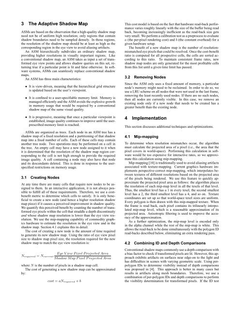
3 The <strong>Adaptive</strong> <strong>Shadow</strong> Map<br />
ASMs are based on the observation that a high-quality shadow map<br />
need not be <strong>of</strong> uniform high resolution; only regions that contain<br />
shadow boundaries need to be sampled densely. In those regions,<br />
the resolution <strong>of</strong> the shadow map should be at least as high as the<br />
corresponding region in the eye view to avoid aliasing artifacts.<br />
An ASM hierarchically subdivides an ordinary shadow map,<br />
providing higher resolutions in visually important regions. Like<br />
a conventional shadow map, an ASM takes as input a set <strong>of</strong> transformed<br />
eye view points and allows shadow queries on this set, returning<br />
true if a particular point is lit and false otherwise. In s<strong>of</strong>tware<br />
systems, ASMs can seamlessly replace conventional shadow<br />
maps.<br />
An ASM has three main characteristics:<br />
• It is view-driven, meaning that the hierarchical grid structure<br />
is updated based on the user’s viewpoint.<br />
• It is confined to a user-specifiable memory limit. Memory is<br />
managed efficiently and the ASM avoids the explosive growth<br />
in memory usage that would be required by a conventional<br />
shadow map <strong>of</strong> the same visual quality.<br />
• It is progressive, meaning that once a particular viewpoint is<br />
established, image quality continues to improve until the userprescribed<br />
memory limit is reached.<br />
ASMs are organized as trees. Each node in an ASM tree has a<br />
shadow map <strong>of</strong> a fixed resolution and a partitioning <strong>of</strong> that shadow<br />
map into a fixed number <strong>of</strong> cells. Each <strong>of</strong> these cells may contain<br />
another tree node. Two operations may be performed on a cell in<br />
the tree. An empty cell may have a new node assigned to it when<br />
it is determined that the resolution <strong>of</strong> the shadow map region corresponding<br />
to the cell is not high enough to provide the required<br />
image quality. A cell containing a node may also have that node<br />
and its descendants deleted. This is done in response to the userspecified<br />
restrictions on memory usage.<br />
3.1 Creating Nodes<br />
At any time there are many cells that require new nodes to be assigned<br />
to them. In an interactive application, it is not always possible<br />
to fulfill all <strong>of</strong> these requirements. Therefore, we use a costbenefit<br />
metric to determine which cells to satisfy. It is only beneficial<br />
to create a new node (and hence a higher resolution shadow<br />
map piece) if it causes a perceived improvement in shadow quality.<br />
We quantify this perceived benefit by counting the number <strong>of</strong> transformed<br />
eye pixels within the cell that straddle a depth discontinuity<br />
and whose shadow map resolution is lower than the eye view resolution.<br />
We use the mip-mapping capability <strong>of</strong> commodity graphics<br />
hardware to estimate the resolution in the eye view and in the<br />
shadow map. Section 4.1 explains this in detail.<br />
The cost <strong>of</strong> creating a new node is the amount <strong>of</strong> time required<br />
to generate its new shadow map. Using the ratio <strong>of</strong> eye view pixel<br />
size to shadow map pixel size, the resolution required for the new<br />
shadow map to match the eye view resolution is:<br />
Eye V iew P ixel P rojected Area<br />
N required = N current<br />
<strong>Shadow</strong> Map P ixel P rojected Area<br />
where N is the number <strong>of</strong> pixels in a shadow map cell.<br />
The cost <strong>of</strong> generating a new shadow map can be approximated<br />
by:<br />
cost = aN required + b<br />
This cost model is based on the fact that hardware read-back performance<br />
varies roughly linearly with the size <strong>of</strong> the buffer being read<br />
back, becoming increasingly inefficient as the read-back size gets<br />
very small. We perform a calibration test as a preprocess to evaluate<br />
a (the per-pixel rendering cost) and b (the constant overhead) for a<br />
given hardware setup.<br />
The benefit <strong>of</strong> a new shadow map is the number <strong>of</strong> resolutionmismatched<br />
eye pixels that could be resolved. Once the cost-benefit<br />
ratio is computed for all prospective cells, the cells are sorted according<br />
to this ratio. To maintain consistent frame rates, new<br />
shadow map nodes are only generated for the most pr<strong>of</strong>itable cells<br />
from this list until a given time limit has passed.<br />
3.2 Removing Nodes<br />
Since the ASM only uses a fixed amount <strong>of</strong> memory, a particular<br />
node’s memory might need to be reclaimed. In order to do so, we<br />
use a LRU scheme on all nodes that were not used in the last frame,<br />
removing the least recently used nodes. If there are no such nodes,<br />
then all nodes are currently visible. In this case, we remove an<br />
existing node only if a new node that needs to be created has a<br />
greater benefit than the existing node.<br />
4 Implementation<br />
This section discusses additional techniques and optimizations.<br />
4.1 Mip-mapping<br />
To determine when resolution mismatches occur, the algorithm<br />
must calculate the projected area <strong>of</strong> a pixel (i.e., the area that the<br />
pixel covers in world-space). Performing this calculation in s<strong>of</strong>tware<br />
would be too expensive for interactive rates, so we approximate<br />
this calculation using mip-mapping.<br />
Mip-mapping [10] is traditionally used to avoid aliasing artifacts<br />
associated with texture-mapping. Current graphics hardware implements<br />
perspective-correct mip-mapping, which interpolates between<br />
textures <strong>of</strong> different resolutions based on the projected area<br />
<strong>of</strong> the pixels being rendered. We use this feature to quickly approximate<br />
the projected pixel area as follows: the algorithm places<br />
the resolution <strong>of</strong> each mip-map level in all the texels <strong>of</strong> that level.<br />
Thus, the smallest level has a 1 in every texel, the second smallest<br />
level has a 2, the third smallest level has a 4, and so on. Texture<br />
coordinates are set up so that world-space texel sizes are uniform.<br />
Every polygon is then drawn with this mip-mapped texture. When<br />
the frame is read back, each pixel contains its trilinearly interpolated<br />
mip-map level, which is a reasonable approximation <strong>of</strong> its<br />
projected area. Anisotropic filtering is used to improve the accuracy<br />
<strong>of</strong> the approximation.<br />
As a further optimization, the mip-map level is encoded only<br />
in the alpha channel while the rest <strong>of</strong> the mip-map is white. This<br />
allows the read-back to be done simultaneously with the polygon ID<br />
read-backs described below, eliminating an extra rendering pass.<br />
4.2 Combining ID and Depth Comparisons<br />
Conventional shadow maps commonly use a depth comparison with<br />
a bias factor to check if transformed pixels are lit. However, this approach<br />
exhibits artifacts on surfaces near edge-on to the light and<br />
has difficulties in scenes with varying geometric scale. Using perpolygon<br />
IDs to determine visibility instead <strong>of</strong> depth comparisons<br />
was proposed in [4]. This approach is better in many cases but<br />
results in artifacts along mesh boundaries. Therefore, we use a<br />
combination <strong>of</strong> per-polygon IDs and depth comparisons to perform<br />
the visibility determination for transformed pixels. If the ID test


