Pile Design with Negative Skin Friction
Pile Design with Negative Skin Friction
Pile Design with Negative Skin Friction

Create successful ePaper yourself
Turn your PDF publications into a flip-book with our unique Google optimized e-Paper software.
Tripartite Meeting and Technical Courses - Geotechnical Engineering<br />
Course Title : <strong>Pile</strong> <strong>Design</strong> <strong>with</strong> <strong>Negative</strong> <strong>Skin</strong> <strong>Friction</strong> by Ir. Liew Shaw Shong<br />
27 June 2002, Puteri Pan Pacific Hotel, Johore<br />
1.0 INTRODUCTION<br />
The phenomenon of negative downdrag has progressively gained attentions from<br />
the engineering profession after many foundation failures due to excessive<br />
downdrag. Failures in either serviceability or ultimate limits or both of structures<br />
are expected if downdrag is not considered in the foundation design, particularly<br />
in settling subsoil.<br />
This note reviews the available design concepts pertaining to this subject,<br />
presents a case history on instrumented piles showing negative skin friction and<br />
finally demonstrates a simplified design approach using the common commercial<br />
spreadsheet, Microsoft Excel. Discussions will be addressed on the load transfer<br />
mechanism at the pile/soil interface, determination of maximum pile axial stress<br />
and depth of neutral plane, performance of the pile subject to downdrag and<br />
parametric study. Methods of reducing downdrag load on piles, like applying slip<br />
coat material on piles, providing pile sleeves and other methods will be<br />
highlighted.<br />
2.0 NEGATIVE SKIN FRICTION & CAUSES<br />
<strong>Negative</strong> skin friction (NSF) is in fact a downward friction imposed on foundation<br />
piles as a result of subsoil settlement. NSF is usually mobilized to ultimate stress<br />
limit in most cases except at very close proximity to the neutral plane as<br />
discussed later. It needs only few millimeters of relative displacement between<br />
the settling subsoil and the pile shaft surface, which is not uncommon to have<br />
relative displacement at the pile-soil interface more than these values in normal<br />
subsoil settlement problem, to fully mobilise the shaft resistance in either upward<br />
or downward directions.<br />
There are five probable, but not limited to, reasons of existence of NSF, namely,<br />
a. Self-weight of unconsolidated recent fill,<br />
b. Surcharge-induced consolidation settlement<br />
c. Consolidation settlement after dissipation of excess pore pressure<br />
induced by pile driving,<br />
d. Lowering of groundwater level,<br />
e. Collapse settlements due to wetting of unsaturated fill, and<br />
f. Crushing of crushable subsoil under sustained loading, causing subsoil<br />
settlement.<br />
Page 1 of 22
Tripartite Meeting and Technical Courses - Geotechnical Engineering<br />
Course Title : <strong>Pile</strong> <strong>Design</strong> <strong>with</strong> <strong>Negative</strong> <strong>Skin</strong> <strong>Friction</strong> by Ir. Liew Shaw Shong<br />
27 June 2002, Puteri Pan Pacific Hotel, Johore<br />
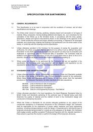
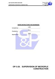
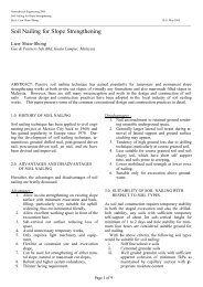
Figure 1 Schematic Diagram of <strong>Pile</strong> <strong>with</strong> NSF<br />
3. ANALYTICAL METHODS<br />
There are several ways in assessing pile subjected to negative skin friction. This<br />
will, or course, involves in determining the dragload and also the location of the<br />
neutral plane in order to assess the pile top movement. Neutral plane represents<br />
the mid point of a transition zone or point (depending on pile-soil interface model)<br />
where the pile shaft friction gradually changing from negative to positive along<br />
the pile shaft. It is also a location on the pile shaft where there is no relative<br />
displacement between the pile shaft and the settling subsoil at that point.<br />
The followings are the conventional engineering solutions in tackling the<br />
analyses of NFS:<br />
a. Closed Form Equations : These approaches normally involves locating<br />
the neutral plane for computation of dragload <strong>with</strong> balancing the<br />
downward loading and the upward resistance. The closed form<br />
solutions based on simplified assumptions offer equations to compute<br />
the dragload and the position of neutral plane. All the physical load<br />
transfer behavours at the pile-soil interface are modelled by simple<br />
equations and therefore can be easily processed using mathematical<br />
operations. Sometimes, engineer will resort to some numerical<br />
iterative computational processes to determine the neutral plane <strong>with</strong><br />
force equilibrium and therefore the dragload. Such approach is more<br />
versatile in dealing <strong>with</strong> heterogeneous subsoil stratum, varying pile<br />
properties and possibility of modeling of slippage and non-linear load<br />
transfer behaviour at the pile-soil interface. For the load transfer<br />
Page 2 of 22
Tripartite Meeting and Technical Courses - Geotechnical Engineering<br />
Course Title : <strong>Pile</strong> <strong>Design</strong> <strong>with</strong> <strong>Negative</strong> <strong>Skin</strong> <strong>Friction</strong> by Ir. Liew Shaw Shong<br />
27 June 2002, Puteri Pan Pacific Hotel, Johore<br />
behaviour, the commonly used models are rigid-plastic model, elastic–<br />
plastic model and hyperbolic model.<br />
b. Continuum Approaches : This usually can only offer solution to very<br />
ideal subsoil condition. For practical use, simplification of the input<br />
parameters are required.<br />
The magnitude of NSF is a function of the ultimate resistance and the relative<br />
displacement between soil and pile shaft interface, and also the pile toe stiffness.<br />
To accurately compute NSF, the subsoil displacement profile, structural pile shaft<br />
stiffness and the pile toe stiffness are required to determine the neutral plane.<br />
The cumulative pile shaft resistance above the neutral plane is a dragload<br />
whereas positive resistance is found below the neutral plane to resist the total<br />
downward loads from NSF and the imposed load at pile top. Maximum pile axial<br />
compression is located at the neutral plane. The conventional rigid-plastic model<br />
tends to over-predict NSF as it does not consider load transfer behaviour and<br />
structural stiffness or compressibility of pile element. The derivation for<br />
computation of dragload and the location of neutral plane based on the rigidplastic<br />
soil model is given in Appendix 1. Figure 1 shows the schematic diagram<br />
of the pile subjected to NSF.<br />
Displacement profile of the compressible or settling subsoil shall be determined<br />
in order to compute the relative displacement between the pile shaft and the<br />
embedded subsoil and therefore the degree of mobilization of the unit shaft<br />
friction for force equilibrium. Despite it is less sensitive in the dragload<br />
computation, the pile settlement behaviour are very sensitive to subsoil<br />
displacement profile. In normal cases, the displacement profile of consolidating<br />
subsoil shows a concave profile, which is fairly different to the linear profile as<br />
assumed in most closed form solutions or continuum approaches.<br />
Shaft Resistance (R su )<br />
The following four methods are usually used to determine the ultimate shaft<br />
resistance:<br />
a. Total Stress Approach (α-Method) : τ ult = α × C u<br />
b. Effective Stress Approach (β-Method) : τ ult = K × σ v ’× Tanδ’= β×σ v ’<br />
c. In-Situ Test Results (SPT-N or CPT) : τ ult = X × SPT-N or f(q u , f s )<br />
d. High Strain Dynamic <strong>Pile</strong> Test : τ mob derived from wave analyses<br />
In normal case, the β-method is the more relevant approach as effective stress<br />
approach is often associated <strong>with</strong> consolidation process of the subsoil.<br />
There are always disputable arguments on whether the unit shaft resistance is<br />
the same for both the upward and downward resistance at the same depth.<br />
Some researchers advocate that the confining stiffness in the embedded subsoil<br />
Page 3 of 22
Tripartite Meeting and Technical Courses - Geotechnical Engineering<br />
Course Title : <strong>Pile</strong> <strong>Design</strong> <strong>with</strong> <strong>Negative</strong> <strong>Skin</strong> <strong>Friction</strong> by Ir. Liew Shaw Shong<br />
27 June 2002, Puteri Pan Pacific Hotel, Johore<br />
and the vertical effective stress will be reduced in the event of upward resistance<br />
from the pile to the soil and therefore reducing the unit shaft resistance. From<br />
the logical point of view, such arguments have the supporting evidence from the<br />
model tests. In the pile group model test in consolidating subsoil, the “hanging<br />
effect” of the centre pile due to the support from the perimeter piles is obvious.<br />
Therefore, the normal way of computing the unit shaft resistance based on the<br />
effective overburden stress <strong>with</strong> the lateral earth pressure coefficient is not<br />
appropriate for the centre pile. Nevertheless, the assumption of same positive<br />
and negative resistance is a conservative approach and will not lead to a unsafe<br />
pile design.<br />
Toe Resistance (R tu )<br />
The following four methods are usually used to determine the ultimate toe<br />
resistance:<br />
a. Total Stress Approach : R tu = A t × Xα × C u<br />
b. Effective Stress Approach : R tu = A t × N t × σ z=D ’<br />
c. In-Situ Test Results (SPT-N or CPT) : R tu = A t × X × SPT-N or f(q u , f s )<br />
d. High Strain Dynamic <strong>Pile</strong> Test : R tu derived from wave analyses<br />
4.0 LOADING NATURE & TIMING OF IMPOSED LOAD<br />
The nature and timing of the imposed loading at pile top will also affect the<br />
magnitude of NSF. Subsequent imposed loads after development of NSF will<br />
further penetrate the pile into the soil and therefore reduce or even eliminate the<br />
NSF developed earlier. This will also result in higher neutral plane, which<br />
corresponds to less NSF but more settlement on pile. Live load, transient load<br />
and cyclic load fall into this category of load, which reduces the NSF developed<br />
after exertion of dead load or sustained load on pile. Due consideration should<br />
be given to this aspect to avoid over-conservatism in pile design.<br />
5.0 SAFETY FACTOR & SERVICEABILITY LIMIT<br />
In the pile design <strong>with</strong> NSF, the maximum pile axial compression (allowable pile<br />
top load plus NSF) should not exceed the allowable structural capacity of the<br />
pile. There are two design considerations where safety factor is applied in a<br />
different way. If the pile is physically sleeved from NSF, than safety factor of two<br />
against ultimate upward resistance from the pile shaft below neutral plane is<br />
normally applied, which is similar to the normal pile design. This proposed safety<br />
factor is to have some control on the serviceability limit of the pile. If the pile is<br />
slip coated, then constant NSF of very much reduced magnitude should be taken<br />
as part of the imposed load in additional to the pile top load and the same safety<br />
factor can be applied.<br />
Page 4 of 22
Tripartite Meeting and Technical Courses - Geotechnical Engineering<br />
Course Title : <strong>Pile</strong> <strong>Design</strong> <strong>with</strong> <strong>Negative</strong> <strong>Skin</strong> <strong>Friction</strong> by Ir. Liew Shaw Shong<br />
27 June 2002, Puteri Pan Pacific Hotel, Johore<br />
In term of safety of factor on geotechnical pile capacity, full shaft resistance along<br />
the entire pile penetration length should be used to compute the ultimate<br />
geotechnical pile capacity. The reason being is that the prerequisite of a pile<br />
achieving the ultimate condition in term of geotechnical capacity is to continue<br />
settling at a limiting load. In such event, the negative skin friction will no more<br />
exist, but <strong>with</strong> the price of larger or even excessive settlement. Therefore,<br />
negative skin friction shall not be considered concurrently <strong>with</strong> the ultimate limit<br />
state of the pile.<br />
6.0 DESIGN CONDITIONS<br />
Due to different subsoil conditions, there are two major pile design conditions as<br />
follows:<br />
a. <strong>Friction</strong>al <strong>Pile</strong> - Higher neutral plane<br />
- Lesser dragload on piles<br />
- Larger foundation settlement (Serviceability to be<br />
checked)<br />
b. End-Bearing <strong>Pile</strong> - Lower neutral plane<br />
- Larger dragload on piles<br />
- Lesser foundation settlement (Safety factor on pile<br />
structure to be checked)<br />
7.0 SINGLE PILE & GROUP PILES<br />
There are fundamental differences of pile design <strong>with</strong> NSF in the conditions of<br />
single pile and group piles. In single pile situation, the dragload is primarily<br />
controlled by the free field subsoil settlement profile and the degree of<br />
mobilisation of the pile shaft resistance to its ultimate limit. Whereas, in the<br />
situation of group piles, the stiffer group piles will disturb the free field settlement<br />
profile and there will be a “hang-up” effect (interior piles will have less NSF and<br />
external piles will have relative more NSF as a single pile). Table 1 shows the<br />
summary of useful expressions for computing NSF at various locations of group<br />
piles. In any cases, the total NSF imposed on the pile or group piles should not<br />
be greater than the total imposed fill weight inducing the subsoil settlement <strong>with</strong>in<br />
the effective coverage of the pile or group piles.<br />
Page 5 of 22
Tripartite Meeting and Technical Courses - Geotechnical Engineering<br />
Course Title : <strong>Pile</strong> <strong>Design</strong> <strong>with</strong> <strong>Negative</strong> <strong>Skin</strong> <strong>Friction</strong> by Ir. Liew Shaw Shong<br />
27 June 2002, Puteri Pan Pacific Hotel, Johore<br />
Table 1 Summary of NSF of Group <strong>Pile</strong>s<br />
<strong>Pile</strong> Briaud et al<br />
Location (1991)<br />
Broms (1976) Combarieu (1974)<br />
Corner ¾ × F n(∞) S×L×S u +<br />
q×(S×L/4+L 2 /16)<br />
7/12× F n(S) +5/12×<br />
F n(∞)<br />
Edge ½ × F n(∞) S×L×S u + q×S×L/4 5/6× F n(S) +1/6× F n(∞)<br />
Interior q×S 2 q×S 2 F n(b)<br />
Notes: S : <strong>Pile</strong> Spacing L : Depth of Neutral Plane<br />
q : Increase of Vertical Effective Stress in Subsoil<br />
S u : Undrained Shear Strength<br />
F n(∞) : NSF in Single <strong>Pile</strong> (needs separate analysis)<br />
: NSF for <strong>Pile</strong> <strong>with</strong> spacing of S (needs separate analysis)<br />
F n(S)<br />
8.0 PILE TESTING REQUIREMENTS<br />
In the testing of pile <strong>with</strong> NSF, there are some special requirements in order to<br />
properly verify the design:<br />
a. Sleeve the pile shaft above predetermined neutral plane to verify the<br />
positive contribution to the pile capacity.<br />
b. Increase test load to two times of the total estimated downward<br />
imposed loads (allowable pile top load plus NSF). This test load is to<br />
overcome the positive shaft resistance above the neutral plane during<br />
testing and simulate NSF in service condition, and then test the<br />
positive resistance of the test pile below the neutral plane <strong>with</strong> safety<br />
factor of two.<br />
c. Instrumented test pile or use of high strain dynamic pile test to monitor<br />
both the load-transfer behaviour along the pile shaft and at the pile toe.<br />
9.0 PREVENTIVE MEASURES<br />
Some preventive measures can be considered to overcome the engineering<br />
problems generated by NSF. There are:<br />
a. Preload the subsoil to reduce or eliminate subsoil settlement by<br />
surcharge before pile installation.<br />
b. Sleeve or isolate the pile shaft from the surrounding settling soil<br />
throughout the portion where the NSF exists or to the depth of the<br />
estimated neutral plane.<br />
c. Application of slip coating (creeping interface medium) on pile shaft.<br />
d. Reserve structural pile capacity for NSF by downgrading the pile top<br />
load.<br />
e. Adopt frictional piles <strong>with</strong> recognition of larges settlement in both the<br />
foundation and superstructure designs.<br />
Page 6 of 22
Tripartite Meeting and Technical Courses - Geotechnical Engineering<br />
Course Title : <strong>Pile</strong> <strong>Design</strong> <strong>with</strong> <strong>Negative</strong> <strong>Skin</strong> <strong>Friction</strong> by Ir. Liew Shaw Shong<br />
27 June 2002, Puteri Pan Pacific Hotel, Johore<br />
The following design considerations shall be taken in designing of slip coating<br />
using bitumen or other creeping interface materials, which will significantly affect<br />
its effectiveness :<br />
a. Thickness of the slip coating material,<br />
b. Rate of Shearing or rate of consolidation settlement,<br />
c. Viscosity of the coating materials<br />
d. Ambient temperature of subsoil.<br />
e. Protection of the coating materials during handling and installation.<br />
10.0 CASE STUDY<br />
A case study of two numbers of 35m long instrumented abutment piles (φ500mm)<br />
installed in granitic residual soil (SPT-N = 5 to 35) was presented. In this case<br />
history, the neutral planes are located at the depth of about 7m to 10m. The<br />
measured NSF ranges from 920kN (middle piles) to 1100kN (edge pile) even in a<br />
reasonably good residual soil <strong>with</strong> 65mm surface settlement under the<br />
embankment loading of 8m high. The details of thus case history can be referred<br />
in a technical paper as attached in Appendix 2.<br />
Findings and Conclusions<br />
The following summarised highlights can be drawn:<br />
a. NSF does exist in reasonably good residual soil even there is only slight<br />
subsoil settlement under loading.<br />
b. Conventional rigid-plastic soil model tends to over-predict NSF, whereas<br />
the elastic-plastic soil model is an improved methodology over rigid-plastic<br />
model. If load transfer behaviour and stiffness of pile element are<br />
considered using numerical iterative process, the NSF prediction will be<br />
more accurate.<br />
c. <strong>Pile</strong> group effect in NSF design is significant and should not be neglected<br />
for an optimised design.<br />
d. Due allowance on pile capacity downgrading or measures to reduce NSF<br />
should be considered.<br />
e. More researches on NSF are needed, particularly for the group piles.<br />
11.0 REFERENCES<br />
Fellenius, B. H. (1998). Recent Advatages in the <strong>Design</strong> of <strong>Pile</strong>s for Axial Loads,<br />
Dragloads, Downdrag, and Settlement. ASCE and Port of NY & NJ Seminar.<br />
22-23 April 1998.<br />
Fellenius, B. H. (1984), <strong>Negative</strong> <strong>Skin</strong> <strong>Friction</strong> and Settlement on piles. 2 nd Int.<br />
Geot. Seminar. November 1984<br />
Page 7 of 22
Tripartite Meeting and Technical Courses - Geotechnical Engineering<br />
Course Title : <strong>Pile</strong> <strong>Design</strong> <strong>with</strong> <strong>Negative</strong> <strong>Skin</strong> <strong>Friction</strong> by Ir. Liew Shaw Shong<br />
27 June 2002, Puteri Pan Pacific Hotel, Johore<br />
Rao, S. N. & Krishnamurthy, N. R. (1982) Studies of <strong>Negative</strong> <strong>Skin</strong> <strong>Friction</strong> in<br />
Model <strong>Pile</strong>s. Technical Note 2, Geotechnical Engineering, Vol. 13: 83-91.<br />
Leifer, S. A. (1994). The Effect of Live Load on Downdrag Forces. ASCE GSP<br />
40:949-961.<br />
Acar, Y. B., Avent, R. R. & Taha, M. R. (1994). Down Drag on <strong>Friction</strong> <strong>Pile</strong>: A<br />
Case History. ASCE GSP 40:986-999.<br />
Bush, R. K. & Briaud J. L. (1994). Measured Downdrag on Seven Coated and<br />
Uncoated <strong>Pile</strong>s in New Orleans. ASCE GSP 40:1010-1027.<br />
Jeong, S. & Briaud J. L (1994). Nonlinear Three Dimensional Analysis of<br />
Downdrag on <strong>Pile</strong> Group. ASCE GSP 40:1366-1384.<br />
Little, J. A. (1994). Downdrag on <strong>Pile</strong>s: Review and Recent Experimentation.<br />
ASCE GSP 40:1805-1826.<br />
Indraratna, B., Balasubramaniam, A. S., Phamvan, P. & Wong, Y. K. (1992).<br />
Development of <strong>Negative</strong> <strong>Skin</strong> <strong>Friction</strong> on Driven <strong>Pile</strong>s in Soft Bangkok Clay.<br />
Canadian Geotechnical Journal. 29: 393-404.<br />
Kuwabara, F. & Poulos, H. G. (1989). Downdrag Forces in Group of piles.<br />
Journal of Geotechnical Engineering, ASCE, Vol 115, No. 6: 806-818.<br />
Wong, K. S. & Teh, C. I. (1995). <strong>Negative</strong> <strong>Skin</strong> <strong>Friction</strong> on <strong>Pile</strong>s in Layered Soil<br />
Deposits. Journal of Geotechnical Engineering, ASCE, Vol 121, No. 6: 457-<br />
465.<br />
Briaud, J. L., Jeong, S. & Bush, R. (1991). Group Effect in the Case of<br />
Downdrag. ASCE GSP 27: 505-518.<br />
Matyas, E. L. & Santamarina, J. C. (1994). <strong>Negative</strong> <strong>Skin</strong> <strong>Friction</strong> and the Neutral<br />
Plane. Canadian Geotechnical Journal. 31: 591-597.<br />
Karasudhi, P. & Poonsawat, P. (1994) Land Subsidence and <strong>Negative</strong> <strong>Skin</strong><br />
<strong>Friction</strong> in <strong>Pile</strong>s. Geotechnical Engineering, Vol.25(2): 21-36.<br />
Kog, Y. C., Karunaratne, G. P. & Lee, S. L. (1986) Effects of <strong>Negative</strong> <strong>Skin</strong><br />
<strong>Friction</strong> on <strong>Pile</strong>s in Layered Soil. Geotechnical Engineering, Vol. 17: 211-234.<br />
Lee, C. Y. (1993). <strong>Pile</strong> Group Under <strong>Negative</strong> <strong>Skin</strong> <strong>Friction</strong>. Journal of<br />
Geotechnical Engineering, ASCE, Vol 119, No. 10: 1587-1600.<br />
Ergun, M. U. & Sonmez, D. (1995). <strong>Negative</strong> <strong>Skin</strong> <strong>Friction</strong> from Surface<br />
Settlement Measurements in Model Group Tests. Canadian Geotechnical<br />
Journal, Vol 32: 1075-1079.<br />
Teh, C. I. & Wong, K. S. (1995). Analysis of downdrag on <strong>Pile</strong> Group.<br />
Geotechnique, Vol 45, No.26: 191-207<br />
Briaud, J. L. (1997). Bitumen Selection for Reduction of Downdrag on <strong>Pile</strong>s.<br />
Journal of Geotechnical and Geoenvironmental Engineering, ASCE, Vol 123,<br />
No. 12: 1127-1134.<br />
Claessen, A. I. M. & Horvat, E. (1974). Reducing <strong>Negative</strong> <strong>Friction</strong> <strong>with</strong> Bitumen<br />
Slip Layers. Journal of the Geotechnical Engineering Division, ASCE, Vol 100,<br />
No. GT8: 925-944.<br />
Page 8 of 22
Tripartite Meeting and Technical Courses - Geotechnical Engineering<br />
Course Title : <strong>Pile</strong> <strong>Design</strong> <strong>with</strong> <strong>Negative</strong> <strong>Skin</strong> <strong>Friction</strong> by Ir. Liew Shaw Shong<br />
27 June 2002, Puteri Pan Pacific Hotel, Johore<br />
APPENDIX 1<br />
ANALYTICAL MODELLING OF NEGATIVE SKIN FRICTION<br />
Page 9 of 22
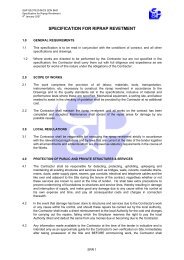
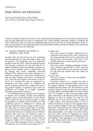
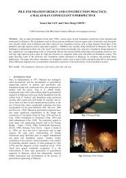
A. Rigid-Plastic Soil Model :<br />
Assumptions :<br />
Tripartite Meeting and Technical Courses - Geotechnical Engineering<br />
Course Title : <strong>Pile</strong> <strong>Design</strong> <strong>with</strong> <strong>Negative</strong> <strong>Skin</strong> <strong>Friction</strong> by Ir. Liew Shaw Shong<br />
27 June 2002, Puteri Pan Pacific Hotel, Johore<br />
a. <strong>Negative</strong>, positive shaft resistances and toe resistance are all fully mobilised<br />
to ultimate condition.<br />
b. The unit shaft and toe resistances are linearly increased <strong>with</strong> depth.<br />
c. Positive (r s ) and negative (q n ) unit shaft friction is the same at the same<br />
depth, i.e. q n = az = r s =bz;<br />
A<br />
Q n =<br />
R su =<br />
A s<br />
⋅ a ⋅<br />
2<br />
⋅a<br />
⋅ D<br />
2<br />
2<br />
s<br />
Z NP<br />
2<br />
----- Eq. (1)<br />
----- Eq. (2)<br />
Q d<br />
q n<br />
r s<br />
Q d<br />
Q u<br />
Q z<br />
Q n<br />
q n = az<br />
r s = bz<br />
Q n<br />
D Z NP<br />
Q NP<br />
R tu<br />
R su<br />
R tu<br />
R u = Q u<br />
z<br />
z<br />
(a)<br />
(b)<br />
(c)<br />
Figure 1 : (a) Single pile subjected to <strong>Negative</strong> <strong>Skin</strong> <strong>Friction</strong>. (b) <strong>Pile</strong> axial load<br />
distribution. (c) Distribution of positive and negative unit shaft resistance, r s and<br />
q n respectively on pile shaft.<br />
Page 10 of 22
Tripartite Meeting and Technical Courses - Geotechnical Engineering<br />
Course Title : <strong>Pile</strong> <strong>Design</strong> <strong>with</strong> <strong>Negative</strong> <strong>Skin</strong> <strong>Friction</strong> by Ir. Liew Shaw Shong<br />
27 June 2002, Puteri Pan Pacific Hotel, Johore<br />
Definitions:<br />
D<br />
B<br />
Z NP<br />
q n<br />
r s<br />
Q d<br />
Q n<br />
Q NP<br />
R tu<br />
R su<br />
Q u<br />
= <strong>Pile</strong> Penetration Length<br />
= <strong>Pile</strong> Diameter<br />
= Depth of Neutral Plane<br />
= <strong>Negative</strong> Unit Shaft Resistance = az (Linearly increasing <strong>with</strong> depth)<br />
= Positive Unit Shaft Resistance = bz (Linearly increasing <strong>with</strong> depth)<br />
= Imposed Load at <strong>Pile</strong> Top<br />
= <strong>Negative</strong> <strong>Skin</strong> <strong>Friction</strong> on <strong>Pile</strong> above Neutral Plane<br />
Z NP<br />
Z NP<br />
= ∫ As<br />
β<br />
nσ<br />
z<br />
' dz = As<br />
K<br />
sn z<br />
⋅ dz<br />
0 ∫ σ ' tanδ<br />
(β refers to Table 1)<br />
0<br />
= <strong>Pile</strong> Axial Load at Neutral Plane<br />
= Ultimate <strong>Pile</strong> Toe Resistance<br />
= '<br />
A c N + σ ' N (N c & N q refers to<br />
A N t t z=<br />
D<br />
σ (N t refers to Table 1) or { }<br />
t<br />
' c z = D<br />
NAVFAC, 1982)<br />
= Ultimate <strong>Pile</strong> Shaft Resistance over Whole Shaft Length<br />
D<br />
D<br />
= ∫ As<br />
β<br />
pσ<br />
z<br />
' dz = As<br />
K<br />
sp z<br />
⋅ dz<br />
0 ∫ σ ' tanδ<br />
(β refers to Table 1)<br />
0<br />
= R u = Ultimate <strong>Pile</strong> Capacity = R tu + R su<br />
q<br />
Table 1 Ranges of φ, β and N t values<br />
Soil Type φ (Degree) β N t<br />
Clay 25 ~ 30 0.25 ~ 0.35 3 ~ 30<br />
Silt 28 ~ 34 0.27 ~ 0.50 20 ~ 40<br />
Sand 32 ~ 40 0.30 ~ 0.60 30 ~ 150<br />
Gravel 35 ~ 45 0.35 ~ 0.80 60 ~ 300<br />
Note : Ontario Highway Bridge <strong>Design</strong> Code (1992)<br />
Two dimensionless parameters are introduced as follows:<br />
a. Ratio of Ultimate <strong>Pile</strong> Capacity to Ultimate Shaft Resistance, α :<br />
Ru<br />
α =<br />
Rsu<br />
b. Factor of Safety on <strong>Pile</strong> Capacity against Ultimate <strong>Pile</strong> Capacity, F s :<br />
Ru<br />
F<br />
s<br />
=<br />
Q<br />
d<br />
Normalised Depth of Neutral Plane to <strong>Pile</strong> Penetration Length using equilibrium<br />
equation, Eq. (3) below for the forces exerted on pile shaft above and below the<br />
Neutral Plane and also the pile toe:<br />
Q<br />
NP<br />
= Q<br />
d<br />
ZNP<br />
+ ∫ Asqndz<br />
= Rtu<br />
+ ∫<br />
0<br />
D<br />
Z NP<br />
A r dz<br />
s<br />
s<br />
------ Eq. (3)<br />
Page 11 of 22
Tripartite Meeting and Technical Courses - Geotechnical Engineering<br />
Course Title : <strong>Pile</strong> <strong>Design</strong> <strong>with</strong> <strong>Negative</strong> <strong>Skin</strong> <strong>Friction</strong> by Ir. Liew Shaw Shong<br />
27 June 2002, Puteri Pan Pacific Hotel, Johore<br />
⇒ Q<br />
d<br />
Z<br />
⇒<br />
D<br />
NP<br />
+ A<br />
s<br />
=<br />
s<br />
2<br />
z<br />
⋅ a ⋅<br />
2<br />
Z NP<br />
= R<br />
tu<br />
⎡<br />
⎢1<br />
( Qd<br />
− R<br />
⎢ −<br />
2<br />
⎢2<br />
D ⋅ A<br />
2 ⋅<br />
⎢⎣<br />
2<br />
tu<br />
s<br />
+ A<br />
2<br />
As<br />
⋅ a ⋅ Z<br />
NP<br />
A<br />
⇔ Qd<br />
+ = Rtu<br />
+<br />
2<br />
2( Qd<br />
− Rtu<br />
) 2 2<br />
⇔<br />
= D − 2Z<br />
NP<br />
A ⋅ a<br />
0<br />
s<br />
s<br />
⎤<br />
) ⎥<br />
⎥ =<br />
⋅ a ⎥<br />
⎥⎦<br />
2<br />
z<br />
⋅ a ⋅<br />
2<br />
2<br />
⋅ a ⋅ ( D<br />
2<br />
D<br />
Z NP<br />
− 2Z<br />
⎡1<br />
( Qd<br />
⎢ −<br />
⎣2<br />
2<br />
⎡ ⎛ Ru<br />
⎞⎤<br />
⎢ ⎜ Ru<br />
− ⎟<br />
Z<br />
⎥<br />
⎡ ⎤<br />
NP<br />
⎢<br />
1 ⎜ Fs<br />
⎟⎥<br />
α 1<br />
⇔ =<br />
= ⎢1<br />
− ⎥<br />
D ⎢2<br />
⎜ R ⎟<br />
su ⎥ 2 ⎣ FS<br />
⎦<br />
⎢ ⎜ ⎟⎥<br />
⎣ ⎝ ⎠⎦<br />
2<br />
NP<br />
)<br />
−<br />
⋅ R<br />
R<br />
su<br />
tu<br />
) ⎤<br />
⎥<br />
⎦<br />
=<br />
⎡1<br />
⎛ Rsu<br />
− Qd<br />
+ R<br />
⎢<br />
⎜<br />
⎣2<br />
⎝ Rsu<br />
tu<br />
⎞⎤<br />
⎟⎥<br />
⎠⎦<br />
------ Eq. (4)<br />
Normalised Dragload at Neutral Plane to Ultimate <strong>Pile</strong> Capacity using Eq. (3) :<br />
Q<br />
NP<br />
= Q<br />
d<br />
+<br />
As<br />
⋅ a ⋅ Z<br />
2<br />
2<br />
NP<br />
=<br />
R<br />
F<br />
u<br />
s<br />
+<br />
2<br />
2<br />
⎛ Z<br />
A ⋅ ⋅ ⋅<br />
⎜<br />
s<br />
a D<br />
⎝ D<br />
2<br />
NP<br />
2<br />
⎞<br />
⎟<br />
⎠<br />
=<br />
R<br />
F<br />
u<br />
s<br />
+ R<br />
su<br />
α ⎡ 1 ⋅ ⋅ ⎢1<br />
−<br />
2 ⎣ Fs<br />
⎤<br />
⎥<br />
⎦<br />
=<br />
R<br />
F<br />
u<br />
s<br />
+<br />
Ru<br />
2<br />
⎡<br />
⎢1<br />
−<br />
⎣<br />
1<br />
F<br />
s<br />
⎤<br />
⎥<br />
⎦<br />
Q ⎛ ⇒<br />
NP 1 1 =<br />
⎜1<br />
+<br />
Ru<br />
2 ⎝ Fs<br />
⎞<br />
⎟<br />
⎠<br />
------ Eq. (5)<br />
Page 12 of 22
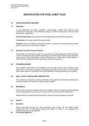
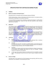
B. Elastic-Plastic Soil Model :<br />
Assumptions:<br />
Tripartite Meeting and Technical Courses - Geotechnical Engineering<br />
Course Title : <strong>Pile</strong> <strong>Design</strong> <strong>with</strong> <strong>Negative</strong> <strong>Skin</strong> <strong>Friction</strong> by Ir. Liew Shaw Shong<br />
27 June 2002, Puteri Pan Pacific Hotel, Johore<br />
a. The pile is rigid and incompressible.<br />
b. The subsoil settlement profile is linear <strong>with</strong> maximum at the ground surface<br />
and decreasing <strong>with</strong> depth.<br />
c. <strong>Negative</strong> and positive shaft resistances are all fully mobilised to ultimate<br />
condition except at the transition zone at the neutral plane.<br />
Absolute<br />
Displacement<br />
δ h<br />
q n<br />
r s<br />
Q d<br />
Q u<br />
Q z<br />
Z NP<br />
(λ- ω)D<br />
λ D<br />
(λ+ω)D<br />
δ sy<br />
Subsoil<br />
Settlement<br />
Profile<br />
Transition<br />
Zone<br />
q n = az<br />
r s = bz<br />
D<br />
Z NP<br />
Q n<br />
Q NP<br />
δ sy<br />
<strong>Pile</strong><br />
Settlement<br />
D<br />
δ t<br />
S<br />
D<br />
R tm<br />
R tu<br />
R su<br />
R u = Q u<br />
z<br />
(a)<br />
z<br />
(b)<br />
z<br />
(c)<br />
q n , r s<br />
( λ z)<br />
⎧<br />
q<br />
nzm<br />
qny<br />
⋅ , q<br />
⎩ ω<br />
ny<br />
⎬<br />
⎭<br />
q ny , r sy<br />
δ sy δ t<br />
( z − λD)<br />
⎧<br />
r<br />
szm<br />
Min⎨rsy<br />
⋅ , r<br />
⎩ ωD<br />
=<br />
sy<br />
⎫<br />
⎬<br />
⎭<br />
R tu<br />
R t<br />
⎪⎧<br />
δ<br />
t<br />
R<br />
tm<br />
Min⎨Rtu<br />
⋅ , R<br />
⎪⎩ δ ty<br />
=<br />
tu<br />
⎪⎫<br />
⎬<br />
⎪⎭<br />
(d)<br />
δ s<br />
Figure 2 : (a) Relative Displacement Profiles. (b) Distribution of positive and<br />
negative unit shaft resistance, r s and q n respectively on pile shaft. (c) <strong>Pile</strong> axial<br />
load distribution. (d) Mobilised Shaft Resistance. (e) Mobilised Toe Resistance.<br />
δ ty<br />
(e)<br />
Page 13 of 22
Tripartite Meeting and Technical Courses - Geotechnical Engineering<br />
Course Title : <strong>Pile</strong> <strong>Design</strong> <strong>with</strong> <strong>Negative</strong> <strong>Skin</strong> <strong>Friction</strong> by Ir. Liew Shaw Shong<br />
27 June 2002, Puteri Pan Pacific Hotel, Johore<br />
Three dimensionless parameters are introduced as follows:<br />
δty<br />
Ψ = S<br />
δ<br />
sy<br />
ω = S<br />
where δ ty is the relative displacement between the pile toe<br />
and the soil at the pile toe that is required to yield the toe<br />
resistance.<br />
where δ sy is the relative displacement between the pile and<br />
the soil around the pile shaft that is required to yield the shaft<br />
resistance.<br />
δ<br />
h<br />
Z<br />
λ = = NP where δh is the relative settlement between the pile head and<br />
S D<br />
the settled ground surface.<br />
Subscripts s, t, y and m denote the shaft, toe, yield and mobilised<br />
respectively.<br />
S denotes the total compression of the subsoil <strong>with</strong>in the pile penetration<br />
length, D by integrating the vertical strain in the said subsoil strata. In this<br />
model, the vertical strain is identical at every level <strong>with</strong>in the subsoil.<br />
δ t is the relative settlement between the pile toe and the settled subsoil at<br />
the pile toe.<br />
Normalised Depth of Neutral Plane to <strong>Pile</strong> Penetration Length using equilibrium<br />
equation, Eq. (6), below for the forces exerted on pile shaft above and below the<br />
Neutral Plane and also the pile toe:<br />
( λ −ω<br />
) D<br />
λD<br />
( λ + ω ) D<br />
D<br />
= NP<br />
Qd<br />
+ ∫ Asqny<br />
dz + ∫ Asq<br />
nzm<br />
dz = ∫ Asrszm<br />
dz + ∫ Asrsy<br />
0 ( λ −ω<br />
) D<br />
λD<br />
( λ + ω ) D<br />
Q dz + R<br />
⇒ Q<br />
=<br />
⇔<br />
+<br />
⇔<br />
∫<br />
( λ + ω ) D<br />
λD<br />
A<br />
Q<br />
s<br />
Q<br />
d<br />
d<br />
d<br />
+<br />
+<br />
∫<br />
( λ −ω<br />
) D<br />
0<br />
A<br />
A<br />
s<br />
s<br />
2<br />
z<br />
⋅ a ⋅<br />
2<br />
= − A<br />
D<br />
( λ + ω ) D<br />
s<br />
A<br />
s<br />
2<br />
z<br />
⋅ a ⋅<br />
2<br />
2<br />
z<br />
⋅ a ⋅<br />
2<br />
⋅ a ⋅ z ⋅ dz +<br />
( λ −ω<br />
) D<br />
0<br />
+ R<br />
tu<br />
( λ −ω<br />
) D<br />
0<br />
t<br />
ty<br />
A<br />
s<br />
A<br />
λD<br />
( λ −ω<br />
) D<br />
( z − λD<br />
)<br />
⋅ a ⋅ z ⋅ ⋅ dz +<br />
ωD<br />
+<br />
δ<br />
⋅<br />
δ<br />
+<br />
∫<br />
s<br />
∫<br />
D<br />
A<br />
s<br />
( λ + ω ) D<br />
2<br />
⎛ λz<br />
⋅ a ⋅<br />
⎜<br />
⎝ 2ω<br />
( λD<br />
− z)<br />
⋅ a ⋅ z ⋅ ⋅ dz<br />
ωD<br />
δ<br />
As<br />
⋅ a ⋅ z ⋅dz<br />
+ Rtu<br />
⋅<br />
δ<br />
3<br />
z ⎞<br />
−<br />
ωD<br />
⎟<br />
3 ⎠<br />
λD<br />
3<br />
2<br />
⎛ z λz<br />
⎞<br />
⋅ a ⋅<br />
⎜ −<br />
ωD<br />
ω<br />
⎟<br />
⎝ 3 2 ⎠<br />
( λ −ω<br />
) D<br />
=<br />
( λ + ω ) D<br />
( λ −ω<br />
) D<br />
+<br />
A<br />
s<br />
A<br />
s<br />
t<br />
ty<br />
2<br />
z<br />
⋅ a ⋅<br />
2<br />
tm<br />
3<br />
2<br />
⎛ z λz<br />
⎞<br />
⋅ a ⋅<br />
⎜ −<br />
ωD<br />
ω<br />
⎟<br />
⎝ 3 2 ⎠<br />
D<br />
( λ + ω ) D<br />
------ Eq. (6)<br />
+ R<br />
( λ + ω ) D<br />
λD<br />
tu<br />
δ<br />
⋅<br />
δ<br />
t<br />
ty<br />
Page 14 of 22
Tripartite Meeting and Technical Courses - Geotechnical Engineering<br />
Course Title : <strong>Pile</strong> <strong>Design</strong> <strong>with</strong> <strong>Negative</strong> <strong>Skin</strong> <strong>Friction</strong> by Ir. Liew Shaw Shong<br />
27 June 2002, Puteri Pan Pacific Hotel, Johore<br />
⇔<br />
+<br />
⇔<br />
+<br />
⇔<br />
⇔<br />
⇒<br />
=<br />
Q<br />
s<br />
R<br />
( λ − ω )<br />
[ ( ) ] ( ) ( δ )<br />
2<br />
S −<br />
h<br />
1 − λ + ω ⋅ R + R − R ⋅<br />
R<br />
α<br />
F<br />
⇔ 2ψλ<br />
λ<br />
F<br />
F<br />
d<br />
u<br />
s<br />
u<br />
s<br />
s<br />
=<br />
= −<br />
A a(<br />
D<br />
− ( λ + ω )<br />
2<br />
⎛<br />
= ⎜ − 2λ<br />
⎝<br />
⎛<br />
= ⎜ − 2λ<br />
⎝<br />
2<br />
2<br />
= −<br />
Z<br />
+<br />
NP<br />
D<br />
As<br />
a(<br />
λ − ω )<br />
2<br />
2<br />
2<br />
2<br />
2<br />
3<br />
ω<br />
+ 1 −<br />
2<br />
3<br />
⎛ 2<br />
+ ⎜<br />
⎝<br />
⎞<br />
+ 1⎟<br />
⋅ R<br />
⎠<br />
ω<br />
)<br />
+ R<br />
( α − 1) λ − ( α − 1)<br />
=<br />
−<br />
−<br />
su<br />
2<br />
⋅ R<br />
2<br />
D<br />
su<br />
2<br />
D<br />
2<br />
u<br />
2<br />
2<br />
⎞<br />
⎟<br />
⎠<br />
+<br />
3 2<br />
3 2<br />
2 2<br />
( λ + ω ) D − ( λ − ω ) D λ ( λ + ω ) D − λ ( λ − ω )<br />
3<br />
3<br />
2<br />
( λ + ω ) − ( λ − ω ) ) λ ( λ + ω ) − λ ( λ − ω )<br />
+<br />
su<br />
( ) ( S − λS<br />
R − R ⋅<br />
)<br />
( ) ( 1 − λ<br />
α − 1 ⋅<br />
)<br />
⎛<br />
− ψ<br />
⎜1<br />
−<br />
⎝<br />
2<br />
( α − 1) ± ( α − 1) − 4 ⋅ 2ψ<br />
⋅ ⎜ − ( α − 1)<br />
⎛<br />
⎜<br />
⎝<br />
4ψ<br />
⎛<br />
⋅ a ⋅ ⎜<br />
⎝<br />
δ<br />
⋅<br />
δ<br />
⎛<br />
⎜<br />
⎝<br />
2 ⋅ 2ψ<br />
2<br />
2<br />
2<br />
( α − 1) + 8ψ<br />
( α − 1) + 8ψ<br />
⎜1<br />
− ω − ⎟ − ( α − 1)<br />
A<br />
tu<br />
s<br />
su<br />
+<br />
t<br />
ty<br />
2<br />
3<br />
δ<br />
3ω<br />
ty<br />
u<br />
2<br />
3<br />
ω<br />
ψ<br />
2<br />
su<br />
α<br />
−<br />
F<br />
α<br />
F<br />
s<br />
s<br />
⎞<br />
⎟<br />
⎠<br />
3ω<br />
−<br />
ψ S<br />
⎞<br />
⎟ = 0<br />
⎠<br />
⎛<br />
−ψ<br />
⎜1<br />
−<br />
⎝<br />
ω<br />
2<br />
3<br />
−<br />
ω<br />
2<br />
α<br />
−<br />
F<br />
s<br />
2<br />
⎞ ⎞<br />
⎟<br />
⎟<br />
⎠ ⎠<br />
⎞<br />
⎟<br />
⋅ R<br />
⎠<br />
2ω<br />
su<br />
2<br />
D<br />
2<br />
⎞<br />
⎟<br />
⎠<br />
⇒<br />
λ<br />
=<br />
Z<br />
NP<br />
D<br />
=<br />
⎛<br />
⎜<br />
⎝<br />
4ψ<br />
2<br />
2<br />
2<br />
( α − 1) + 8ψ<br />
( α − 1) + 8ψ<br />
⎜1<br />
− ω − ⎟ − ( α − 1)<br />
2<br />
3<br />
α<br />
F<br />
s<br />
⎞<br />
⎟<br />
⎠<br />
------ Eq. (7)<br />
Normalised Dragload at Neutral Plane to Ultimate <strong>Pile</strong> Capacity using Eq. (6) :<br />
Q<br />
NP<br />
= Q<br />
= Q<br />
= Q<br />
d<br />
d<br />
d<br />
= Q<br />
∫<br />
d<br />
+<br />
0<br />
+ A<br />
+<br />
( λ −ω<br />
) D<br />
s<br />
( λ −ω<br />
) D<br />
∫<br />
0<br />
A<br />
2<br />
z<br />
⋅ a ⋅<br />
2<br />
A q<br />
dz +<br />
⋅ a ⋅ z ⋅ dz +<br />
( λ −ω<br />
) D<br />
0<br />
2<br />
Asa(<br />
λ − ω ) D<br />
+<br />
2<br />
s<br />
s<br />
ny<br />
2<br />
+<br />
+<br />
λD<br />
∫<br />
s<br />
( λ −ω<br />
) D<br />
A<br />
s<br />
∫<br />
A q<br />
λD<br />
nzm<br />
( λ −ω<br />
) D<br />
A<br />
dz<br />
2<br />
⎛ λz<br />
⋅ a ⋅<br />
⎜<br />
⎝ 2ω<br />
3<br />
⎛ λ D<br />
A ⋅ ⋅ ⎜<br />
s<br />
a<br />
⎝<br />
s<br />
( λD<br />
− z)<br />
⋅ a ⋅ z ⋅ ⋅ dz<br />
ωD<br />
3<br />
z ⎞<br />
−<br />
⎟<br />
3ω<br />
D ⎠<br />
2<br />
− λ<br />
2ω<br />
λD<br />
( λ −ω<br />
) D<br />
( λ − ω )<br />
2<br />
D<br />
2<br />
−<br />
λ<br />
3<br />
D<br />
2<br />
− ( λ − ω )<br />
3ω<br />
3<br />
D<br />
2<br />
⎞<br />
⎟<br />
⎠<br />
Page 15 of 22
=<br />
=<br />
=<br />
=<br />
=<br />
R<br />
F<br />
u<br />
s<br />
R<br />
F<br />
u<br />
s<br />
R<br />
F<br />
u<br />
s<br />
R<br />
F<br />
u<br />
s<br />
R<br />
F<br />
u<br />
s<br />
+<br />
+<br />
+<br />
+<br />
+<br />
R<br />
R<br />
R<br />
R<br />
R<br />
su<br />
su<br />
su<br />
su<br />
su<br />
⎡<br />
⋅ ⎢<br />
⎢⎣<br />
⎡<br />
⋅ ⎢λ<br />
⎢⎣<br />
⎡<br />
⋅ ⎢λ<br />
⎣<br />
⎡<br />
⋅ ⎢λ<br />
⎣<br />
⎡<br />
⋅ ⎢λ<br />
⎣<br />
( λ − ω )<br />
2<br />
2<br />
2<br />
2<br />
2<br />
− 2ωλ<br />
− 2ωλ<br />
− 2ωλ<br />
− ωλ<br />
⎛ λ<br />
+ ⎜<br />
⎝<br />
+ ω<br />
+ ω<br />
+ ω<br />
ω<br />
+<br />
3<br />
2<br />
Tripartite Meeting and Technical Courses - Geotechnical Engineering<br />
Course Title : <strong>Pile</strong> <strong>Design</strong> <strong>with</strong> <strong>Negative</strong> <strong>Skin</strong> <strong>Friction</strong> by Ir. Liew Shaw Shong<br />
27 June 2002, Puteri Pan Pacific Hotel, Johore<br />
3<br />
2<br />
2<br />
2<br />
⎤<br />
⎥<br />
⎦<br />
− λ<br />
ω<br />
⎛ λ<br />
+ ⎜<br />
⎝<br />
⎛<br />
+<br />
⎜ 2λ<br />
⎝<br />
3<br />
( )<br />
2 3<br />
( λ − ω ) 2 λ − ( λ − ω )<br />
3<br />
− λ<br />
2<br />
⎛<br />
+<br />
⎜ωλ<br />
−<br />
⎝<br />
2<br />
2<br />
3<br />
3<br />
( λ − 2ωλ<br />
+ ω ) 2( λ − ( λ − ω ) )<br />
− ωλ<br />
2ω<br />
3<br />
−<br />
2<br />
ω<br />
− 2λ<br />
⎞⎤<br />
⎟⎥<br />
⎠⎦<br />
2<br />
3ω<br />
+ 2ωλ<br />
−<br />
2ω<br />
−<br />
3<br />
⎞⎤<br />
⎟<br />
⎥<br />
⎠⎥⎦<br />
2<br />
⎞⎤<br />
⎟⎥<br />
⎠⎦<br />
3ω<br />
⎞⎤<br />
⎟<br />
⎥<br />
⎠⎥⎦<br />
Q<br />
⇒<br />
R<br />
NP<br />
u<br />
=<br />
1<br />
F<br />
s<br />
1<br />
+<br />
α<br />
⎛<br />
⋅<br />
⎜λ<br />
⎝<br />
− ωλ +<br />
2 ω<br />
2<br />
⎞<br />
⎟<br />
3 ⎠<br />
------ Eq. (8)<br />
As shown in Figure 2, the thickness of the transition zone is :<br />
t<br />
trans<br />
=<br />
sy<br />
( λ − ω) D − ( λ + ω) D = 2 ωD<br />
= 2 D<br />
δ<br />
S<br />
The above expression implies that the thickness of the transition zone, t trans<br />
, will<br />
reduce when the stiffness of the shaft resistance increases (δ sy reduces) and/or<br />
compressibility of the soil increases (S increases).<br />
Eq. (7) and (8) will only be valid when the following conditions are satisfied;<br />
a. Transition zone is fully contained <strong>with</strong>in the length, D, of the pile<br />
penetration inclusively.<br />
Upper limit : (λ - ω) D ≥ 0 ⇒ (λ - ω) ≥ 0<br />
Lower limit : (λ + ω) D ≤ D ⇒ (λ + ω) ≤ 1<br />
b. For the valid expression of mobilised toe resistance,<br />
δ<br />
R tm<br />
R tu<br />
δ<br />
t<br />
= , toe<br />
ty<br />
movement, δ t , shall be <strong>with</strong>in the movement, δ ty . i.e. δ t ≤ δ ty<br />
S = δ<br />
Qδ<br />
t<br />
t<br />
+ δ<br />
≤ δ<br />
ty<br />
h<br />
⇔ δ<br />
⇒ S − δ<br />
t<br />
= S − δ<br />
h<br />
≤ δ<br />
ty<br />
h<br />
δ<br />
h<br />
⇔<br />
S<br />
δ<br />
+<br />
S<br />
ty<br />
≥ 1 ⇔ λ + ψ ≥ 1<br />
Page 16 of 22
Tripartite Meeting and Technical Courses - Geotechnical Engineering<br />
Course Title : <strong>Pile</strong> <strong>Design</strong> <strong>with</strong> <strong>Negative</strong> <strong>Skin</strong> <strong>Friction</strong> by Ir. Liew Shaw Shong<br />
27 June 2002, Puteri Pan Pacific Hotel, Johore<br />
Rigid-Plastic Soil Model is a special case of Elastic-Plastic Soil Model, in which if<br />
the following conditions are satisfied, then Eq. (7) and (8) in the Elastic-Plastic<br />
Soil Model will become Eq. (4) and (5) in the Rigid-Plastic Soil Model.<br />
a. Full toe resistance is mobilised <strong>with</strong> the toe movement reaching yield<br />
toe resistance.<br />
δ<br />
t<br />
= δ ty<br />
and S δ<br />
t<br />
+ δ<br />
h<br />
= ⇔ λ + ψ = 1<br />
b. When the stiffness of the shaft resistance becomes infinite,<br />
δ sy<br />
= 0 ⇒ ω = 0<br />
Page 17 of 22
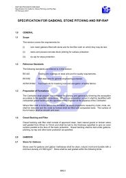
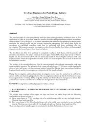
C. Numerical Iterative Approach<br />
Hyperbolic Soil Model<br />
Tripartite Meeting and Technical Courses - Geotechnical Engineering<br />
Course Title : <strong>Pile</strong> <strong>Design</strong> <strong>with</strong> <strong>Negative</strong> <strong>Skin</strong> <strong>Friction</strong> by Ir. Liew Shaw Shong<br />
27 June 2002, Puteri Pan Pacific Hotel, Johore<br />
w pi<br />
P si<br />
w si<br />
Q P si , P ti<br />
n<br />
R tu<br />
(a)<br />
w pi<br />
Hyperbolic Function<br />
P<br />
P<br />
si<br />
ti<br />
=<br />
=<br />
wi<br />
⎛ 1 w ⎞<br />
i<br />
⎜ + R<br />
⎟<br />
sf<br />
⎝ k<br />
si<br />
Psui<br />
⎠<br />
wi<br />
⎛ 1 w ⎞<br />
i<br />
⎜ + R<br />
⎟<br />
tf<br />
⎝ kti<br />
Ptui<br />
⎠<br />
P ti<br />
w si<br />
w i = w si - w pi<br />
(b)<br />
Z NP<br />
D<br />
z<br />
w i = w si - w pi<br />
S<br />
Absolute<br />
Displacement<br />
w si = Subsoil<br />
Settlement Profile<br />
w pi = <strong>Pile</strong> Settlement<br />
(c)<br />
Figure 3 : (a) Supporting Springs at Discretised <strong>Pile</strong> Node Points. (b) Hyperbolic<br />
Function of the Supporting Springs. (c) Displacement Profiles of <strong>Pile</strong> and Soil.<br />
Hyperbolic Function for pile axial load at Node I :<br />
P<br />
i<br />
=<br />
⎛ 1<br />
⎜<br />
⎝ ki<br />
w<br />
i<br />
+ R<br />
f<br />
wi<br />
P<br />
ui<br />
⎞<br />
⎟<br />
⎠<br />
------ Eq. (9)<br />
Two dimensionless parameters, namely<br />
⇒ w<br />
i<br />
=<br />
P<br />
i<br />
( 1−<br />
P )<br />
i<br />
where<br />
wi<br />
and P<br />
i<br />
;<br />
P<br />
w<br />
w<br />
w<br />
i<br />
i<br />
P<br />
i<br />
= R<br />
f<br />
;<br />
i<br />
=<br />
f<br />
;<br />
ui<br />
=<br />
Pui<br />
wui<br />
R<br />
P<br />
k<br />
ui<br />
i<br />
To derive tangential stiffness of the hyperbolic function, differentiate equation Eq.<br />
(9) to get;<br />
dPi<br />
dw<br />
i<br />
k<br />
i<br />
= ------ Eq. (10)<br />
( 1+<br />
w ) 2<br />
i<br />
Page 18 of 22
<strong>Pile</strong> Shaft<br />
Initial Stiffness at Node i of <strong>Pile</strong> Shaft :<br />
Tripartite Meeting and Technical Courses - Geotechnical Engineering<br />
Course Title : <strong>Pile</strong> <strong>Design</strong> <strong>with</strong> <strong>Negative</strong> <strong>Skin</strong> <strong>Friction</strong> by Ir. Liew Shaw Shong<br />
27 June 2002, Puteri Pan Pacific Hotel, Johore<br />
Randolph & Wroth (1978) :<br />
k<br />
si<br />
=<br />
2 π<br />
⋅ G<br />
i<br />
li<br />
Ln<br />
⎛r<br />
⎜<br />
⎝<br />
m<br />
r<br />
o<br />
⎞<br />
⎟<br />
⎠<br />
where G i : Soil shear modulus<br />
l i : <strong>Pile</strong> segment length<br />
r m : Limit radius<br />
r o : <strong>Pile</strong> radius<br />
L : <strong>Pile</strong> length<br />
ν’ s : Poisson’s ratio<br />
rm<br />
= 2ρ<br />
⋅ ( 1−υ'<br />
s<br />
)L for Gibson soil model (Increasing stiffness<br />
<strong>with</strong> depth)<br />
GL<br />
2<br />
ρ =<br />
G<br />
L<br />
Shaft Resistance :<br />
P<br />
i<br />
=<br />
⎛ 1<br />
⎜<br />
⎝ k<br />
si<br />
w<br />
i<br />
+ R<br />
sf<br />
wi<br />
P<br />
sui<br />
⎞<br />
⎟<br />
⎠<br />
<strong>Pile</strong> Toe<br />
Initial Stiffness at <strong>Pile</strong> Toe :<br />
Randolph & Wroth (1978) :<br />
k<br />
si<br />
4Giro<br />
⋅<br />
=<br />
( 1−υ'<br />
)<br />
s<br />
Toe Resistance :<br />
P<br />
i<br />
=<br />
⎛ 1<br />
⎜<br />
⎝ kti<br />
w<br />
i<br />
+ R<br />
tf<br />
wi<br />
P<br />
tui<br />
⎞<br />
⎟<br />
⎠<br />
Correlation of Parameters :<br />
Shear Modulus, G i :<br />
G<br />
i<br />
=<br />
E'<br />
i<br />
( + υ ' ) 2( 1+υ<br />
)<br />
2 1<br />
s<br />
=<br />
E<br />
i<br />
s<br />
For Clay,<br />
G<br />
E' i<br />
Ei<br />
2E 50<br />
2E50<br />
= = =<br />
2 1<br />
( + υ'<br />
) 2( 1+<br />
υ ) 2( 1+<br />
0.5) 3<br />
i<br />
=<br />
s<br />
s<br />
Page 19 of 22
Tripartite Meeting and Technical Courses - Geotechnical Engineering<br />
Course Title : <strong>Pile</strong> <strong>Design</strong> <strong>with</strong> <strong>Negative</strong> <strong>Skin</strong> <strong>Friction</strong> by Ir. Liew Shaw Shong<br />
27 June 2002, Puteri Pan Pacific Hotel, Johore<br />
where E’ i : Drained initial tangent modulus<br />
E i : Undrained initial tangent modulus (=2E 50 by<br />
Duncan et al. 1980)<br />
E 50 : Secant deviatoric modulus at 50% failure<br />
stress (refer to Figure 4)<br />
ν’ s : Drained Poisson’s ratio<br />
ν s : Undrained Poisson’s ratio (=0.5)<br />
For Sand,<br />
E'<br />
i<br />
⎛<br />
= KPa<br />
⎜ K<br />
⎝<br />
o<br />
σ '<br />
P<br />
a<br />
v<br />
⎟ ⎞<br />
⎠<br />
n<br />
as recommended by Duncan et al., 1980)<br />
where K : Modulus number (refer to Table 2)<br />
n : Modulus exponent (refer to Table 2)<br />
P a : Atmospheric pressure<br />
Coefficient of Earth Pressure at rest, K o (Mayne & Kulhawy, 1982) :<br />
Poisson’s ratio, ν’ s :<br />
For Sand,<br />
o<br />
Sinφ<br />
'<br />
( 1 φ'<br />
) OCR<br />
K = − Sin<br />
K<br />
For Clay, refer to Table 4<br />
o<br />
υ '<br />
s<br />
= based on theory of elasticity<br />
( 1+ K<br />
o<br />
)<br />
Table 2 Recommended Parameter for Sand<br />
Soil Consistency D r<br />
K s K n<br />
(%)<br />
Very loose 0 ~ 15 0.6 ~ 1.0 250 0.7<br />
Loose 15 ~ 35 1.0 ~ 1.4 500 0.7<br />
Medium Dense 35 ~ 65 1.4 ~ 1.6 1000 0.7<br />
Dense 65 ~ 85 1.6 ~ 2.0 1500 0.7<br />
Very Dense 85 ~ 100 2.0 ~ 2.4 2000 0.7<br />
Table 3 Recommended Interface <strong>Friction</strong> Angle for Sand (Kulhawy, 1984)<br />
<strong>Pile</strong> Material<br />
δ (Degrees)<br />
Rough Concrete φ’<br />
Smooth Concrete 0.8φ’ ~ φ’<br />
Steel<br />
0.5φ’ ~ 0.9φ’<br />
Timber<br />
0.8φ’ ~ 0.9φ’<br />
Page 20 of 22
Tripartite Meeting and Technical Courses - Geotechnical Engineering<br />
Course Title : <strong>Pile</strong> <strong>Design</strong> <strong>with</strong> <strong>Negative</strong> <strong>Skin</strong> <strong>Friction</strong> by Ir. Liew Shaw Shong<br />
27 June 2002, Puteri Pan Pacific Hotel, Johore<br />
Table 4 Recommended Poisson’s Ratio for Clay (Puolos & Davis, 1980)<br />
Soil Consistency<br />
υ’ s<br />
Soft Non Consolidated Clay 0.3 ~ 0.4<br />
Firm Clay 0.2 ~ 0.3<br />
Stiff Over Consolidated Clay 0.1 ~ 0.2<br />
1200<br />
1000<br />
E 50 /C u Ratio<br />
800<br />
600<br />
400<br />
200<br />
0<br />
0 20 40 60 80 100<br />
Plasticity Index, PI (%)<br />
Figure 4 : (a) Ratio of Secant Deviatoric Modulus at 50% Failure Stress to<br />
Undrained Shear Strength<br />
The above expressions can be easily implemented in a computer spreadsheet<br />
application <strong>with</strong> an iterative scheme for assessing NSF.<br />
Page 21 of 22
Tripartite Meeting and Technical Courses - Geotechnical Engineering<br />
Course Title : <strong>Pile</strong> <strong>Design</strong> <strong>with</strong> <strong>Negative</strong> <strong>Skin</strong> <strong>Friction</strong> by Ir. Liew Shaw Shong<br />
27 June 2002, Puteri Pan Pacific Hotel, Johore<br />
APPENDIX 2<br />
TECHNICAL PAPER<br />
Page 22 of 22