System 3™ Modular Media Filter System
System 3™ Modular Media Filter System
System 3™ Modular Media Filter System

Create successful ePaper yourself
Turn your PDF publications into a flip-book with our unique Google optimized e-Paper software.
RELEASE RELEASE<br />
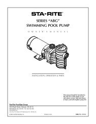
<strong>System</strong> 3 <strong>Modular</strong> <strong>Media</strong> <strong>Filter</strong> <strong>System</strong><br />
O W N E R’ S<br />
M A N U A L<br />
OUTLET<br />
INLET<br />
2160 1295<br />
INSTALLATION, OPERATION & PARTS<br />
For Model Numbers and Descriptions See Page 5.<br />
This manual should be furnished to<br />
the end user of this filter; its use will<br />
reduce service calls and chance of injury<br />
and will lengthen filter life.<br />
Sta-Rite Pool/Spa Group<br />
293 Wright Street, Delavan, WI 53115<br />
North America: 800-752-0183, FAX 800-582-2217<br />
International: 262-728-5551, FAX: 262-728-4461, TELEX: ITT 4970245<br />
Union City, TN • Delavan, WI • Mississauga, Ont. • Murrieta, CA<br />
U.S. PATENT NO. 5190651 (Other patents pending)<br />
© 2000, Sta-Rite Industries, Inc. Printed in U.S.A. S340 (Rev. 1/25/00)
SYSTEM 3 MODULAR MEDIA<br />
FILTER SYSTEM<br />
To avoid unneeded service calls, prevent possible injuries, and get the most<br />
out of your filter system, READ THIS MANUAL CAREFULLY!<br />
The <strong>System</strong> 3 <strong>Modular</strong> <strong>Media</strong> <strong>Filter</strong> <strong>System</strong> Pool Pumps:<br />
• Without a cord or with a 3’ cord or no cord are for use with permanently<br />
installed pools ONLY (see CAUTION #7, below).<br />
• With a 25’ cord are for use with storable pools ONLY (see CAUTION #8,<br />
below).<br />
Table of Contents<br />
Safety Instructions ......................................................................................2-3<br />
General Information ......................................................................................4<br />
Specifications / Model Numbers and Descriptions.........................................5<br />
Installation ....................................................................................................6<br />
Electrical .......................................................................................................7<br />
Initial Startup / Operation ..............................................................................8<br />
<strong>Filter</strong> Disassembly / Assembly ..................................................................9-10<br />
Module Cleaning Procedure........................................................................10<br />
Special Cleaning Instruction.....................................................................10<br />
<strong>System</strong> Inspection / Winterizing...................................................................11<br />
Pump Service .........................................................................................11-12<br />
Troubleshooting Guide - Pump....................................................................13<br />
Troubleshooting Guide - <strong>Filter</strong> .....................................................................14<br />
Repair Parts List......................................................................................15-18<br />
Warranty .....................................................................................................19<br />
IMPORTANT SAFETY INSTRUCTIONS<br />
When installing and using electrical equipment, basic safety precautions should always be followed,<br />
including the following:<br />
1. READ AND FOLLOW ALL SAFETY INSTRUCTIONS.<br />
2. To reduce the risk of injury, do not permit<br />
children to use this product unless they are closely supervised<br />
at all times.<br />
3. Risk of electrical shock. Connect only to a<br />
grounding type receptacle protected by a ground-fault circuit-interrupter<br />
(GFCI). Contact a qualified electrician if you<br />
cannot verify that the receptacle is protected by a GFCI.<br />
4. Do not bury cord. Locate cord to minimize abuse from<br />
lawn mowers, hedge trimmers, and other equipment.<br />
5. To reduce the risk of electrical shock,<br />
replace a damaged cord immediately.<br />
6. To reduce the risk of electrical shock, do<br />
not use an extension cord to connect unit to electrical supply;<br />
provide a properly located outlet.<br />
7. Permanent pool pumps are for use with permanently<br />
installed pools and may also be used with hot<br />
tubs and spas if so marked. Do not use with storable pools.<br />
A permanently installed pool is constructed in or on the<br />
ground or in a building such that it cannot be readily disassembled<br />
for storage. A storable pool is constructed so that<br />
it may be readily disassembled for storage and reassembled<br />
to its original integrity.<br />
8. Storable pool pumps are for use with<br />
storable pools only. Do not use with permanently installed<br />
pools. A storable pool is constructed so that it is capable<br />
of being readily disassembled for storage and reassembled<br />
to its original integrity. A permanently installed pool is<br />
constructed in or on the ground, or in a building, such that<br />
it cannot be readily disassembled for storage.<br />
SAVE THESE INSTRUCTIONS<br />
2
WARNING<br />
READ AND FOLLOW SAFETY<br />
INSTRUCTIONS!<br />
This is the safety alert symbol. When you see this symbol on your filter or in<br />
this manual, look for one of the following signal words and be alert to the<br />
potential for personal injury.<br />
warns about hazards that will cause death, serious personal injury, or<br />
major property damage if ignored.<br />
Hazardous Pressure!<br />
Can cause tank<br />
explosion.<br />
Do not connect filter to<br />
compressed air under any<br />
circumstances.<br />
warns about hazards that can cause death, serious personal injury, or<br />
major property damage if ignored.<br />
warns about hazards that will or can cause minor personal injury or<br />
property damage if ignored.<br />
NOTICE indicates special instructions not related to hazards.<br />
Carefully read and follow all safety instructions in this manual and on equipment.<br />
Keep safety labels in good condition; replace if missing or damaged.<br />
Incorrectly installed or tested equipment may fail, causing<br />
severe injury or property damage. Read and follow instructions in<br />
owner's manual when installing and operating equipment. Have a<br />
trained pool professional perform all pressure tests.<br />
1. Do not connect system to a city water system or other external source of<br />
pressurized water.<br />
2. Use equipment only in a pool or spa installation.<br />
3. Trapped air in system can cause explosion. BE SURE all air is out of system before<br />
operating or testing equipment.<br />
Before pressure testing, make the following safety checks:<br />
• Check all clamps, bolts, lids, lock rings and system accessories before testing.<br />
• Release all air in system before testing.<br />
• Tighten Sta-Rite trap lids to 30 ft. lbs. (4.1 kg-cm) torque for testing.<br />
• Water pressure for test must be less than 25 PSI (172 kPa).<br />
• Water Temperature for test must be less than 100 o F. (38 o C).<br />
• Limit test to 24 hours. After test, visually check system to be sure it is ready for<br />
operation. Remove trap lid and retighten hand tight only.<br />
NOTICE: These parameters apply to Sta-Rite equipment only. For<br />
non-Sta-Rite equipment, consult equipment manufacturer.<br />
3
Head<br />
ForeArm<br />
Upper<br />
Arm<br />
Leg Joint<br />
GENERAL INFORMATION<br />
When to Clean the <strong>Filter</strong><br />
The filter module should normally be<br />
cleaned when the pressure gauge reading<br />
increases 10 PSI over the start-up pressure<br />
(record the start-up pressure under<br />
“Owner’s Information”, below, right).<br />
In some pools, accessories such as fountains<br />
or pool cleaners may be noticeably<br />
affected by the normal decrease in flow as<br />
the filter becomes dirty. If so, clean the filter<br />
more frequently (that is, at a pressure<br />
increase of less than 10 PSI) in order to<br />
maintain the required flow.<br />
WARNING<br />
• Clean a new pool as well as possible before filling pool and operating filter.<br />
Excess dirt and large particles of foreign matter in the system can cause serious<br />
damage to the filter and pump.<br />
• With a modular media filter system in place and operating correctly, clean<br />
water is returned to the pool faster than pool water is being contaminated. A<br />
typical pool installation will require approximately one week to obtain and<br />
maintain the sparkle that your filter is capable of giving you.<br />
• Maximum pressure is 50 PSI (345 kPa). DO NOT connect the filter to a city<br />
water system.<br />
Hazardous pressure. Open air release valve to vent all air<br />
from system before operating system. NEVER operate filter with air<br />
trapped inside.<br />
• The Sta-Rite modular media filter system is designed to filter water for swimming<br />
pools and spas. On a new installation, we recommend:<br />
1. Disassemble the filter after the initial cleanup.<br />
Hazardous pressure. To prevent severe injury or major property<br />
damage, exactly follow "<strong>Filter</strong> Disassembly/Assembly Procedure" on<br />
Pages 8 and 9.<br />
2. Remove and hose down the filter module to remove contaminants.<br />
• Maintain pool water pH between 7.2 and 7.6.<br />
• Make sure that internal air bleed tube and filter are clean and installed properly<br />
at top of module before operating filter.<br />
• Make sure that Posi-Lok Ring is securely locked in place before operating<br />
filter.<br />
• Maintain pressure gauge in good working order. Replace a damaged gauge<br />
immediately.<br />
• Cleaning interval is based on pressure rise, not on length of time filter is operated.<br />
Different water conditions will have different normal cleaning intervals.<br />
• Check local codes for restrictions on waste water disposal requirements.<br />
NOTICE: Some pool disinfectants may clog filter module. To maximize<br />
module life and filter cycle time, closely follow disinfectant manufacturer’s<br />
instructions when cleaning pool or filter. Failure to follow these instructions<br />
may affect warranty coverage of the module.<br />
ForeArm<br />
Upper<br />
Arm<br />
Body<br />
Leg Joint<br />
Leg Joint<br />
Leg Joint<br />
Owner’s Information<br />
Serial Number ____________________________________________________<br />
Dealer ___________________________________________________________<br />
Risk of falls and injury.<br />
<strong>Filter</strong> surface is<br />
slippery.<br />
Do not allow children to<br />
stand or play on filter.<br />
Dealer’s Telephone #_______________________________________________<br />
Purchase Date ____________________________________________________<br />
Installation Date ___________________________________________________<br />
Pressure Gauge Reading at Startup ___________________________________<br />
4
A<br />
G<br />
R E<br />
R E<br />
L<br />
P<br />
R<br />
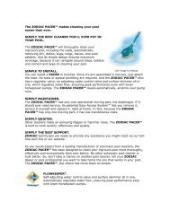
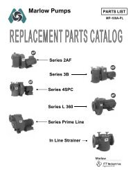
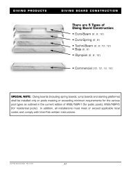
SPECIFICATIONS / MODEL DESCRIPTIONS<br />
Air Release Valve<br />
(Pressure Gauge<br />
Behind)<br />
Upper<br />
Tank<br />
Shell<br />
Posi-Lok<br />
Ring<br />
Safety<br />
Latch<br />
Lower<br />
Tank<br />
Shell<br />
Drain<br />
Plug<br />
7.4"<br />
(188 mm)<br />
Outlet<br />
2" NPT<br />
19.5" (495 mm)<br />
Inlet<br />
2" NPT<br />
32.75"<br />
(832 mm)<br />
2" NPT x 1-1/2" NPT<br />
Reducer Bushing<br />
Pump<br />
Suction<br />
1-1/2" NPT<br />
11"<br />
(279 mm)<br />
43.5"<br />
(1105 mm)<br />
Minimum<br />
Service<br />
Height<br />
Table 1 - <strong>Filter</strong> Specifications<br />
Model No.<br />
PLM100 PLM150<br />
<strong>Filter</strong> Area sq. ft. (m 2 ) 100(9.3) 150(14)<br />
Max. Rated Flow GPM (LPM)*<br />
Residential 100(379) 150(568)<br />
Commercial 37(140) 56(212)<br />
Max. Operating Pressure PSI (kPa) 50(345) 50(345)<br />
Max. Continuous Water<br />
Temperature F(C) 104°(40°) 104°(40°)<br />
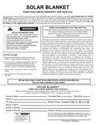
* For best water clarity and filter cycle length, restrict<br />
water flow to 50 GPM (189 LPM).<br />
24 (165)<br />
22 (152)<br />
20 (138)<br />
V E<br />
M O<br />
E<br />
R<br />
K<br />
C<br />
L O<br />
U G E<br />
R E S S U<br />
15" (381 mm)<br />
30" (762 mm)<br />
V E<br />
O<br />
E M<br />
RELEASE<br />
2157 1295<br />
23"<br />
(584 mm)<br />
Pressure Drop in<br />
Pounds per Square Inch (kPa)<br />
18 (124)<br />
16 (110)<br />
14 (97)<br />
12 (88)<br />
10 (69)<br />
8 (55)<br />
6 (41)<br />
4 (28)<br />
L O<br />
C K<br />
A IR<br />
E A S E<br />
C K<br />
L O<br />
19"<br />
(483 mm)<br />
2 (14)<br />
10<br />
(38)<br />
20<br />
(76)<br />
40<br />
(151)<br />
60<br />
(227)<br />
80<br />
(303)<br />
100<br />
(378)<br />
Flow in Gallons Per Minute (LPM)<br />
2497 0796<br />
120<br />
(454)<br />
140 160<br />
(529) (606)<br />
150<br />
(568)<br />
R<br />
E M<br />
O<br />
V<br />
E<br />
FIGURE 1 – Dimensions in inches (mm)<br />
2158 1295<br />
FIGURE 2 – Pressure Drop Curve<br />
PLM100JWAE-03 PLM100JWAF-03<br />
PLM150JWAE-03 PLM150JWAF-03<br />
Hoses, Adapters, Clamps, and U.S.A. Spec. Motor<br />
(Includes 3’ Cord w/Straight Plug)<br />
PLM100JWAE-04 PLM100JWAF-04<br />
PLM150JWAE-04 PLM150JWAF-04<br />
Adapters, Clamps, and U.S.A. Spec. Motor<br />
(Includes 3’ Cord w/Straight Plug)<br />
Model Descriptions<br />
PLM100JWAE-06 PLM100JWAF-06<br />
PLM150JWAE-06 PLM150JWAF-06<br />
Adapters, Clamps, and Canadian Spec. Motor<br />
(Includes 25’ Cord w/Straight Plug)<br />
PLM100JWAE-12 PLM100JWAF-12<br />
PLM150JWAE-12 PLM150JWAF-12<br />
Adapters, Clamps, and U.S.A. Spec. Motor<br />
(Includes 3’ Cord w/Twist-Lok Plug)<br />
5
INSTALLATION<br />
Installation of filter should only be done by qualified, licensed personnel.<br />
Hazardous voltage.<br />
Can shock, burn,<br />
or cause death.<br />
Disconnect power<br />
before working<br />
on pump or motor.<br />
NOTICE<br />
Make sure that the filter and all piping<br />
can be drained for winterizing.<br />
See “Winterizing”, Page 10.<br />
Assembly:<br />
• Unpack filter system and check it for transit damage.<br />
• Open the accessory package and install the pressure gauge (with the filter<br />
screen under it; see exploded view, Page 15) in the open port on top of the filter<br />
tank. Do not overtighten.<br />
• Install hoses with adapters and clamps provided in the accessory package. Run<br />
one line from the skimmer to the pump suction port. Run the other line from the<br />
filter outlet to the pool inlet fitting.<br />
<strong>Filter</strong> mount must:<br />
• Provide weather and freezing protection.<br />
• Provide adequate ventilation and drainage for pump.<br />
• Provide space and lighting for easy access for routine maintenance. (See Figure<br />
1 for space requirements.)<br />
• Be installed with the trap suction inlet below the pool water level at all times (to<br />
allow the pump to prime).<br />
• Be on a reasonably level surface and provide adequate drainage.<br />
Piping:<br />
• Piping must conform to local/state plumbing and sanitary codes.<br />
• Use teflon tape, Plasto-Joint Stik ®1 , or Silastic RTV #732 ® on all male connections<br />
of plastic pipe and fittings. DO NOT use pipe compounds on plastic pipe;<br />
it will cause the pipe to crack. Do not use sealant on unions – assemble them<br />
dry and hand tight.<br />
• Support pipe independently to prevent strains on filter or pump.<br />
• Fittings restrict flow; for best efficiency use fewest possible fittings.<br />
• For ease of maintenance, use Sta-Rite union couplings to connect the piping to<br />
the filter inlet and outlet ports.<br />
• Keep piping tight and free of leaks: pump suction line leaks may cause trapped<br />
air in filter tank or loss of prime at pump; pump discharge line leaks may show<br />
up as dampness or jets of water.<br />
• NOTICE: Overtightening can crack filter ports.<br />
Valves:<br />
• Install valves on both sides of the filter to isolate filter for easy servicing.<br />
NOTICE: Install heater downstream of filter. If heater does not incorporate a<br />
check valve, install one at the heater inlet to prevent hot water from backing up<br />
into the filter. <strong>Filter</strong> modules damaged by excessive heat will void the warranty.<br />
• A check valve installed ahead of filter inlet will prevent contaminants from<br />
draining back into pool.<br />
1<br />
Lake Chemical Co., Chicago, IL<br />
6
ELECTRICAL<br />
Risk of electrical shock. Plug pump into a grounded, GFCI-protected 115<br />
Volt circuit only. Incorrect voltage can cause fire or seriously damage<br />
motor and voids warranty. Protect cord from water and physical damage.<br />
GFCI tripping indicates an electrical problem. If GFCI trips and will not<br />
reset, have a qualified electrician inspect and repair electrical system.<br />
Hazardous voltage.<br />
Can shock, burn,<br />
or cause death.<br />
Disconnect power<br />
before working<br />
on pump or motor.<br />
Risk of electrical shock. Unplug motor before servicing or repairing<br />
pump or motor.<br />
Wiring:<br />
Install a Ground Fault Circuit Interrupter (GFCI) in circuit; it will sense a short<br />
circuit to ground and disconnect power before it becomes dangerous to pool or<br />
spa users. For size of GFCI required and test procedures for GFCI, see manufacturer’s<br />
instructions.<br />
In case of power outage, check GFCI for tripping (which will prevent normal<br />
water circulation); reset if necessary.<br />
Do not connect any other lights or appliances to the same circuit.<br />
Match circuit breaker size to Table II below.<br />
• Do not modify cord, plug, or receptacle. If an existing circuit must be used<br />
and the receptacle and plug do not match exactly, consult a licensed electrician.<br />
• Do not use an extension or drop cord with this system; it could cause a fire<br />
hazard or low voltage problems. Wet cords cause shock hazards. Extension<br />
cords can easily become cut or frayed and dangerous when placed across<br />
yard areas or walkways.<br />
Voltage:<br />
Voltage at motor must be not more than 10% above or below motor nameplate<br />
rated voltage or motor may overheat, causing overload tripping and reduced<br />
component life. If voltage is less than 90% or more than 110% of rated<br />
voltage when motor is running at full load, consult power company.<br />
Table II–Recommended Fusing Data, 115 Volt 60 Hz Motors.<br />
Model Motor Max Load Branch Circuit Breaker<br />
No. H.P. Amps Rating (Amps)<br />
JWPA5E7L-2A1, -2A2 1 12.0 15<br />
JWPA5E7C-2A3, 2A3U 1 11.9 15<br />
JWPA5F7L-2A1, -2A2, -A1 1-1/2 16.0 20<br />
JWPS5F7C-2A3, 2A3U 1-1/2SPL 11.9 15<br />
NOTICE Values given are for pump motor only. Do not put any other accessories on<br />
this circuit.<br />
1 HP <strong>Filter</strong> system with<br />
Model No. suffix:<br />
-03, -04, or -06<br />
1-1/2 HP <strong>Filter</strong> system<br />
with Model No. suffix:<br />
-03, -04, or -06<br />
All <strong>Filter</strong> systems with<br />
Model No. suffix:<br />
-12 or -15<br />
1 HP Pumps with -2A2<br />
suffix and Canadian Spec<br />
Pumps use 15-amp straight<br />
outlet, above.<br />
1-1/2 HP Pumps with<br />
-2A2 suffix use 20 amp<br />
straight outlet, above.<br />
All Pumps with<br />
-2A1 suffix use 20-amp<br />
twist-lock outlet, above.<br />
FIGURE 3 - Plug configurations<br />
7
INITIAL START-UP<br />
Hazardous suction. Pump suction can trap or tear body parts,<br />
especially with children. Do not block suction. Small children using pool must<br />
ALWAYS have close adult supervison!<br />
Do not operate system with water temperature above 104° F (40° C).<br />
Hazardous pressure.<br />
Can cause severe<br />
injury or major<br />
property damage<br />
from tank blow up.<br />
Release all pressure<br />
and read instructions<br />
before working on filter.<br />
Latch<br />
Tab<br />
RELEASE RELEASE<br />
2149 1195<br />
Figure 4 – Rotate Posi-Lok<br />
Ring until tab locks behind the<br />
safety latch.<br />
NEVER run pump dry. Running pump dry may damage seals,<br />
causing leakage and flooding. Fill pump with water through the hair and lint<br />
strainer lid before starting the pump.<br />
Do not add chemicals to pool directly in the pool skimmer.<br />
Adding undiluted chemicals may damage pump and void warranty.<br />
Be sure pump is OFF before starting procedure.<br />
Do not operate these filters at more than 50 PSI (345 kPa) under any<br />
circumstances!<br />
1. Securely lock Posi-Lok ring in place by rotating ring CLOCKWISE until it<br />
“clicks” past the safety latch (see Figure 4). Stop turning as soon as the ring<br />
clicks past the latch. The ring may feel slightly loose, but it will tighten up<br />
when pump is on and filter is under pressure.<br />
2. Fill trap on pump with water.<br />
3. Open air release valve on top of filter.<br />
4. Open isolation valves.<br />
5. Start pump to purge air from system.<br />
6. When steady stream of water comes from air release valve, close the<br />
valve.<br />
NOTICE: Leaking around the Posi-Lok ring may indicate that the ring is<br />
not fully locked. In this case, proceed as follows:<br />
A. Stop the pump, close the isolation valves, and open the air release valve<br />
to release any pressure within the filter.<br />
B. Remove the drain plug and drain all water from the filter.<br />
C. Push down on the top of the filter to fully seat the upper tank shell.<br />
D. Rotate the Posi-Lok clockwise until it locks behind the safety latch<br />
(see Figure 4).<br />
E. If the ring was already locked, remove it and the upper tank shell.<br />
Inspect and clean the O-ring and all sealing surfaces. Relubricate the<br />
O-ring.<br />
NOTICE: Lubricate O-ring only with the silicone grease provided or equivalent,<br />
as other lubricants may cause the ring to swell. DO NOT lubricate<br />
Posi-Lok ring or threads on lower tank shell as this may collect grit and<br />
make removal difficult.<br />
After filter is operating, record filter pressure gauge reading in owner's manual<br />
for future use.<br />
NOTICE: When installed on a new pool, after approximately 48 hours of operation<br />
disassemble filter and clean out plaster dust, construction debris, etc.<br />
(see “Module Cleaning Procedure", Page 9).<br />
OPERATION<br />
Priming Pump:<br />
Fill pump with water through hair and lint strainer lid opening.<br />
Open suction and discharge valves before starting system.<br />
Make sure that pool water is 2” - 3” (51mm - 76mm) above bottom of skimmer<br />
opening and/or other suction outlets.<br />
Water Maintenance:<br />
Keep water level at least two inches (51mm) above bottom of skimmer opening<br />
when system is not in use. Failure to do so can allow air to enter system, causing<br />
pump to lose prime and filter to entrap air.<br />
Maintain pH at 7.2 to 7.6 in pool.<br />
8
Figure 5 – Depress Safety safety Latch latch to<br />
unscrew Posi-Lok to unscrew Ring. Posi-Lok<br />
Figure 6 – Insert ring tab in slot in<br />
2152 1195<br />
filter body.<br />
Figure 7 – Roll ring to one side to<br />
loosen upper tank half.<br />
Small<br />
Catch<br />
Figure 8 – Safety Latch<br />
RELEASE RELEASE<br />
RELEASE RELEASE<br />
FILTER DISASSEMBLY/<br />
ASSEMBLY PROCEDURE<br />
Hazardous pressure. Before disassembling filter:<br />
1. STOP PUMP.<br />
2. CLOSE isolation valves.<br />
3. OPEN air release valve and drain fitting.<br />
4. WAIT until all pressure is released and water drained from filter tank and<br />
system before loosening Posi-Lok Ring.<br />
Disassembly:<br />
1. Stop the pump.<br />
2. Close isolation valves to prevent flooding.<br />
3. Open air release valve on top of filter tank to release all pressure from inside<br />
of tank.<br />
NOTICE: Make sure that waste water disposal complies with local codes<br />
and ordinances.<br />
4. Remove drain plug and drain all water from tank.<br />
5. Remove Posi-Lok ring as follows:<br />
a. Press safety latch (below the ring) toward the tank to release it (see Figure<br />
5).<br />
b. Hold latch in the release position and rotate ring COUNTERCLOCKWISE<br />
to remove. If ring is difficult to turn, tap gently with a rubber mallet to<br />
overcome initial resistance.<br />
NOTICE: DO NOT use screwdriver or bladed instrument that may damage<br />
shell surfaces to pry tank shells apart.<br />
6. Separate upper and lower tank shell halves using tabs on bottom of<br />
Posi-Lok ring. Insert tab into slot located at tank joint and twist ring to pry<br />
shell halves apart. See Figures 6 and 7.<br />
7. Remove O-ring from upper tank shell. Inspect for cuts, cracking, deformation<br />
or signs of wear; replace if necessary.<br />
NOTICE: To avoid strain or damage, allow filter module to drain before lifting<br />
it out of the tank.<br />
SAFETY LATCH (See Figure 8)<br />
The purpose of the safety latch is to hold the Posi-Lok ring in the locked position.<br />
If the latch is damaged, replace it as follows:<br />
1. Press down on the small catch behind the safety latch and press or tap the<br />
latch out of the “Tee” slot in the tank (see Figure 8).<br />
2. Snap the new latch into position.<br />
NOTICE: DO NOT operate the filter if the safety latch is damaged or will<br />
not hold the Posi-Lok ring in the locked position.<br />
Assembly:<br />
1. Inspect and clean the tank, ring threads and O-ring groove. Replace damaged<br />
parts as necessary.<br />
2. Install the filter by placing the port in the bottom of the filter cartridge over<br />
the tank outlet port. Push down firmly to seal.<br />
3. Ensure that the air bleed assembly on top of the module is clean and properly<br />
mounted.<br />
NOTICE: Lubricate O-ring only with the silicone grease provided or equivalent,<br />
as other lubricants may cause the ring to swell. DO NOT lubricate<br />
Posi-Lok ring or threads on lower tank shell as this may collect grit and<br />
make removal difficult.<br />
9
When to Clean the <strong>Filter</strong><br />
The filter module should normally be<br />
cleaned when the pressure gauge reading<br />
increases 10 PSI over the start-up pressure<br />
(record the start-up pressure under<br />
“Owner’s Information”, Page 3).<br />
In some pools, accessories such as fountains<br />
or pool cleaners may be noticeably<br />
affected by the normal decrease in flow as<br />
the filter becomes dirty. If so, clean the filter<br />
more frequently (that is, at a pressure<br />
increase of less than 10 PSI) in order to<br />
maintain the required flow.<br />
Recommended Specialty<br />
<strong>Filter</strong> Cleaners<br />
<strong>Filter</strong> Cleanse,<br />
Great Lakes Biochemical<br />
BIOGUARD Strip Kwik,<br />
BIOGUARD KleenIt,<br />
Softswim ® <strong>Filter</strong> Cleaner,**<br />
BIOLABS, Inc.<br />
<strong>Filter</strong> Kleen,<br />
Haviland Products Co.<br />
BAQUA CLEAN, **<br />
Zeneca, Inc.<br />
** MUST be used when<br />
using any PHMB based<br />
sanitizer.<br />
4. Install the O-ring in the upper tank shell O-ring groove. Be sure that the<br />
O-ring is clean and not twisted.<br />
5. Push the upper tank shell into the lower tank shell to compress the O-ring.<br />
6. Place the Posi-Lok ring squarely over the tank shell threads and rotate<br />
COUNTERCLOCKWISE until the ring falls into the slots; then rotate<br />
CLOCKWISE until securely latched.<br />
7. Follow instructions in the “Initial Startup” section of this manual.<br />
MODULE CLEANING PROCEDURE<br />
Follow all steps in the “Disassembly” section of this manual.<br />
The filter module should be removed and cleaned when pressure rises more<br />
than 10 psi (69 kPa) above startup pressure. See also “When to Clean the<br />
<strong>Filter</strong>,” at left.<br />
Risk of chemical burns. Do not attempt to acid clean the filter or<br />
module. If the filter requires acid cleaning, have a trained pool professional do<br />
the job.<br />
NOTICE: When sanitizing your pool using PHMB (polyhexamethylene biquanide<br />
based) cleaners, use only PHMB cleaners to clean the module. When<br />
using PHMB sanitizers, the filter module MUST be cleaned more thoroughly<br />
and frequently than for a pool using chlorine. Follow manufacturer’s instructions<br />
carefully. Use of any other type of cleansers with PHMB pool sanitizers<br />
will void the filter’s warranty.<br />
NOTICE: Avoid washing filter debris into the outlet port. Remove drain plug<br />
and flush foreign material from inside of tank before removing filter module.<br />
1. With a hose equipped with a soft flow nozzle, wash as much dirt as possible<br />
off of the filter module while it is still inside the tank. Allow tank to drain<br />
completely.<br />
2. Make sure that the inside of the tank is clean. Lift out the module and hose it<br />
down thoroughly. Spray the entire module surface. Allow module to drain.<br />
3. Inspect the module. If necessary, repeat the washing operation. If the module<br />
is damaged, replace it.<br />
NOTICE: If this cleaning method does not remove all deposits, see “Special<br />
Cleaning Instructions” section in this manual.<br />
4. Inspect and clean air bleed filter at top of module.<br />
5. Follow all steps in the “Assembly” and “Initial Startup” sections of this manual.<br />
Special Cleaning Instructions:<br />
Use this procedure to clean scale or oils which are not removed by hosing<br />
down module. Be sure to dispose of spent chemicals according to all applicable<br />
codes and waste disposal ordinances. Use a soft stream nozzle to minimize<br />
flying water and spray.<br />
Risk of fire or explosion. Isolate filter from system before chemical<br />
cleaning; rinse filter and elements completely before returning to service.<br />
If filter cannot be isolated, remove media and clean at another location. Follow<br />
chemical manufacturer’s instructions for use. Do not mix chemicals except as<br />
directed by manufacturer. Do not allow cleaning chemicals to mix with or to<br />
come in contact with chlorine, bromines, other chemicals, or chemical feed<br />
devices.<br />
1. Sponge or spray the module according to chemical manufacturer’s directions.<br />
2. If soaking is required, remove the module from the filter tank and submerge<br />
it in a separate tank. Follow cleaner manufacturer’s instructions carefully.<br />
3. After completing chemical manufacturer’s instructions, drain and rinse the<br />
module completely. Dispose of cleaners in accordance with local codes and<br />
disposal ordinances.<br />
4. Rinse the inside of the filter tank. Drain it completely.<br />
5. Follow instructions in the “Assembly” and “Initial Startup” sections of this<br />
manual.<br />
10
SYSTEM INSPECTION<br />
General:<br />
Wash the outside of the filter with a mild detergent and water. Rinse off with a<br />
hose.<br />
NOTICE: DO NOT use solvents to clean the filter; solvents may damage plastic<br />
components in the system.<br />
NOTICE: Open the air bleed valve and bleed all air from the filter each time<br />
the pump is stopped and restarted.<br />
Weekly Inspection:<br />
1. Remove debris from the pool skimmer basket.<br />
2. Stop the pump; open the air release valve to release all pressure.<br />
3. Remove the trap cover and basket; remove debris.<br />
4. Check the pump for leaks. If found, see the pump owner's manual.<br />
5. Replace the trap basket and the cover. Tighten the cover securely hand<br />
tight. DO NOT use a lid wrench to tighten it.<br />
6. Start the pump. When the filter air release valve runs a solid stream of<br />
water, close the valve.<br />
7. When the system has returned to normal operation, check the filter pressure.<br />
If the filter pressure is 10 PSI (69kPa) or more higher than the initial<br />
startup pressure, the filter needs cleaning. See “Module Cleaning<br />
Procedure”, Page 9.<br />
WINTERIZING<br />
NOTICE<br />
The filter outlet piping will not empty<br />
through the filter drain. Make sure that<br />
the outlet piping has a separate drain for<br />
winterizing.<br />
Explosion hazard. Purging the system with compressed air can<br />
cause components to explode, with risk of severe injury or death to anyone<br />
nearby. Use only a low pressure (below 5 PSI), high volume blower when air<br />
purging the pump, filter, or piping.<br />
NOTICE: Protect the filter from freezing. Allowing the filter to freeze will damage<br />
it and will void the warranty.<br />
1. Clean the filter according to instructions (Page 9) before winterizing.<br />
2. Stop the pump.<br />
3. Open the air release valve; open all the system valves.<br />
4. Remove the drain plugs from the trap, pump, and filter.<br />
5. Drain the system piping.<br />
A. Gravity drain system as far as possible.<br />
B. Protect areas which retain water with non-toxic propylene glycol<br />
antifreeze (“RV antifreeze”).<br />
6. Loosen the union nuts (if used) to drain all water from the filter interior.<br />
Leave these nuts loose until the system is restarted.<br />
7. Disassemble the filter (follow instructions under “<strong>Filter</strong> Disassembly”, Pages<br />
8 and 9). Remove the filter module and store it in a warm, dry area.<br />
8. If the filter is equipped with an optional internal spring check valve (in the<br />
tank outlet), manually open the check valve to allow any water trapped in<br />
the tank to drain.<br />
9. Cover the filter with plastic or tarpaulin to prevent water entrance and<br />
freezing.<br />
PUMP SERVICE<br />
Pump should only be serviced by qualified personnel.<br />
For continued protection against possible electric shock, use only identical<br />
replacement parts when servicing.<br />
Before removing trap cover:<br />
1. STOP PUMP before proceeding.<br />
11
Figure 9<br />
Figure 10<br />
Figure 11<br />
Figure 12<br />
3<br />
5<br />
1<br />
2<br />
START HERE<br />
604 0993<br />
Figure 13 - Torque Sequence<br />
4<br />
6<br />
2. CLOSE GATE VALVES in suction and discharge pipes.<br />
3. RELEASE ALL PRESSURE from pump and piping system.<br />
To avoid dangerous or fatal electrical shock hazard, turn OFF power to<br />
motor before working on pump or motor.<br />
No lubrication or regular maintenance is needed beyond reasonable care and periodic<br />
cleaning of strainer basket. Trap cover O-Ring is internally lubricated and<br />
needs no additional lubrication.<br />
If shaft seal is worn or damaged, repair as follows:<br />
Pump Disassembly:<br />
1. Unplug motor before servicing or repairing pump or motor.<br />
2. Close all valves in suction and discharge piping.<br />
3. Remove drain plugs from the bottom of pump and trap; drain pump completely.<br />
4. Disconnect pipe unions (or clamps) on suction and discharge piping. Remove<br />
hold down bolts and withdraw complete pump/motor/trap assembly.<br />
5. Remove cap screws (Key No. 16, Pages 16 and 17) from front plate (Key<br />
No. 13). Remove front plate with trap (Key No. 20) attached. Remove and<br />
inspect O-Ring (Key No. 12).<br />
6. Remove end cap (Key No. 2) from motor.<br />
7. Hold motor shaft with 7/16” wrench on flats on motor shaft; unscrew impeller<br />
(Key No. 11).<br />
8. Carefully remove rotating half of seal (Key No. 10) from impeller sleeve.<br />
Twist as you pull; make sure you do not damage surface of sleeve where<br />
seal both seats and seals. See Figure 9.<br />
9. Remove motor throughbolts (see Figure 10). Remove seal plate (Key No.<br />
9). Tap stationary half of seal out of seal plate (see Figure 11).<br />
10.If necessary, disconnect electrical wiring from motor terminal board and<br />
remove motor (Key No. 6) from motor cover (Key No. 8; -06 models only).<br />
Pump Assembly:<br />
1. Examine seal cup and O-Rings. Replace anything that shows signs of wear<br />
or damage.<br />
2. Check the shaft seal (Key No. 10) for scoring, scratches, chips, etc., and for<br />
any signs of damage to spring or retainer. Replace if any wear or damage is<br />
visible.<br />
3. Press stationary half of seal into seal plate (Key No. 9) using finger pressure<br />
only (see Figure 12). Make sure seal is firmly and evenly seated.<br />
4. Install rotating half of seal on impeller sleeve. Push it onto sleeve until it<br />
butts against back of impeller.<br />
5. Insert impeller sleeve through center hole in seal plate (Key No. 9). Thread<br />
flinger (Key No. 7) over the end of the impeller sleeve.<br />
6. If motor has been removed from motor cover, reinstall it now. Set up seal<br />
plate (Key No. 9) in front of motor cover; hold motor shaft with 7/16”<br />
wrench on shaft flats (under cap) and thread impeller through center hole<br />
in seal plate onto shaft. Make sure that flinger is in place on impeller<br />
sleeve – not loose on shaft.<br />
7. Install motor throughbolts; make sure seal plate butts firmly against motor<br />
endbell.<br />
8. Install front plate (Key No. 13). Tighten cap screws in sequence as shown<br />
in Figure 13; tighten to 30 inch-lbs. (34.5 cm-kg.) torque.<br />
9. Reinstall drain plugs; reinstall pump and motor on base and tighten holddown<br />
bolts.<br />
10.Reconnect unions; tighten hand tight only.<br />
12
TROUBLESHOOTING GUIDE – PUMP<br />
Read and understand safety and operating instructions<br />
in this manual before doing any work on<br />
pump.<br />
A. Pump does not operate:<br />
1. Check GFCI (Ground Fault Circuit Interrupter) for<br />
proper operation according to GFCI manufacturer’s<br />
instructions.<br />
2. Check for blown fuses, circuit breakers, or disconnected<br />
electrical wiring.<br />
3. Check for sand locked impeller. Disconnect power<br />
to motor; follow pump disassembly instructions,<br />
Pages 10 and 11. Clean out sand from impeller<br />
and from wear ring in front plate. Reassemble according<br />
to instructions, Page 11.<br />
4. Consult dealer/installer or service representative.<br />
B. Motor runs, but does not pump water or pressurize<br />
system:<br />
1. Check to make sure all valves are open.<br />
2. Check skimmer, trap basket, and piping for debris<br />
or obstructions.<br />
3. Check pump impeller for obstructions such as<br />
hair, leaves, grass, or stones. Follow “Pump<br />
Disassembly” instructions, under “Pump Service”<br />
on Pages 10 and 11.<br />
4. Consult with dealer/installer or service representative.<br />
C. Excessive air in system – pump loses prime:<br />
1. Make sure water level in skimmer is at least 2”<br />
above bottom of skimmer throat with system not<br />
operating.<br />
2. Make sure that there are no leaves in suction piping<br />
and skimmer basket.<br />
3. Make sure there is no vortex (whirlpool) at the<br />
skimmer suction; add water to pool if necessary.<br />
4. Consult dealer/installer or service representative.<br />
D. Circuit breaker in home panel trips repeatedly:<br />
1. Breaker must be of correct rating (see Page 6).<br />
2. If breaker is a GFCI breaker, test according to<br />
GFCI manufacturer’s instructions.<br />
3. Be sure no other lights and appliances are on circuit.<br />
4. Check wiring size leading to pump. Undersize<br />
wire will cause overheating and excessive amp<br />
draw, leading to the circuit breaker tripping.<br />
Circuit wiring to the receptacle serving the pump<br />
must meet code for the load on the circuit. If in<br />
doubt, consult a licensed electrician.<br />
5. Consult dealer/installer or service representative.<br />
13
TROUBLESHOOTING GUIDE – FILTER<br />
1. Short Cycle Time:<br />
NOTICE: Cycle Time will vary with each installation<br />
and between different areas of the country. The following<br />
causes and remedies are for cycle times shorter<br />
than normal for your area.<br />
A. Chlorine residual too low; maintain proper residual<br />
(consult pool professional for recommendation).<br />
B. Flow rate too high; restrict flow to rated capacity<br />
of filter (see instruction plate on filter or specifications<br />
on Page 4).<br />
C. <strong>Filter</strong> is too small; install an additional filter.<br />
D. <strong>Filter</strong> module is dirty or plugged; thoroughly clean<br />
the filter (see No. 4, “Plugged Module Cloth”, and<br />
“Module Cleaning Procedure", Page 9).<br />
E. Water is chemically out of balance; consult pool<br />
professional.<br />
F. Algae in the pool. Apply heavy dose of chlorine or<br />
algicide as recommended by the pool manufacturer.<br />
2. Low Flow/High Pressure:<br />
A. Elements plugged; clean filter thoroughly (see<br />
Page 9).<br />
B. Pipe blocked downstream from filter; remove obstruction.<br />
C. Piping too small; use larger pipe (consult dealer<br />
for sizing).<br />
D. <strong>Filter</strong> area too small; install an auxiliary filter (consult<br />
dealer for recommendation).<br />
E. Outlet port check valve obstructed (if applicable);<br />
remove obstruction to allow valve to open.<br />
3. Low Flow/Low Pressure:<br />
A. Pump too small; consult dealer for recommendations.<br />
B. Plugged pump or plugged hair and lint trap; clean<br />
thoroughly.<br />
4. Plugged Module Cloth:<br />
A. Insufficient cleaning; follow cleaning instructions<br />
closely and clean thoroughly (see Page 9).<br />
B. Water is chemically out of balance; consult pool<br />
professional.<br />
C. Excessive air in filter. Vent air from tank and check<br />
for pump suction pipe leaks. Clean air bleed filter<br />
in module assembly with a hose and soft flow<br />
nozzle.<br />
D. <strong>Filter</strong> is too small. Install an additional filter.<br />
E. Pool water contains iron. See “Special Cleaning<br />
Instructions”, Page 9.<br />
F. Heavy or improper application of powdered chlorine<br />
tablets using a binder. See “Special Cleaning<br />
Instructions”, Page 9.<br />
G. Algae in the pool. Apply heavy dose of chlorine<br />
or algicide as recommended by the pool manufacturer.<br />
H. Use of incorrect chemicals with PHMB sanitizers.<br />
Replace filter module.<br />
5. Pool Water Not Clean:<br />
A. Chlorine residual too low; maintain adequate<br />
chlorine residual (consult pool service technician<br />
for recommendation).<br />
B. <strong>Filter</strong> module cloth torn, plugged, or punctured;<br />
replace module.<br />
C. Inadequate turnover rate; consult dealer to verify<br />
that equipment is properly sized for your pool.<br />
D. Pump is too large and is overpumping. Reduce the<br />
flow rate.<br />
E. The filter is installed backwards. Reinstall it correctly.<br />
F. Pool water contains iron. See “Special Cleaning<br />
Instructions”, Page 9.<br />
G. Heavy or improper application of powdered chlorine<br />
tablets using a binder. See “Special Cleaning<br />
Instructions”, Page 9.<br />
H. Algae in the pool. Apply heavy dose of chlorine or<br />
algicide as recommended by the pool manufacturer.<br />
6. Pool Accessories Stop Working:<br />
A. Clean filter and observe performance of accessories.<br />
B. If accessories perform better after filter has been<br />
cleaned, use a shorter cleaning cycle for the filter<br />
(that is, clean the filter after a pressure rise of less<br />
than 10 PSI).<br />
14
RELEASE RELEASE<br />
1<br />
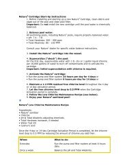
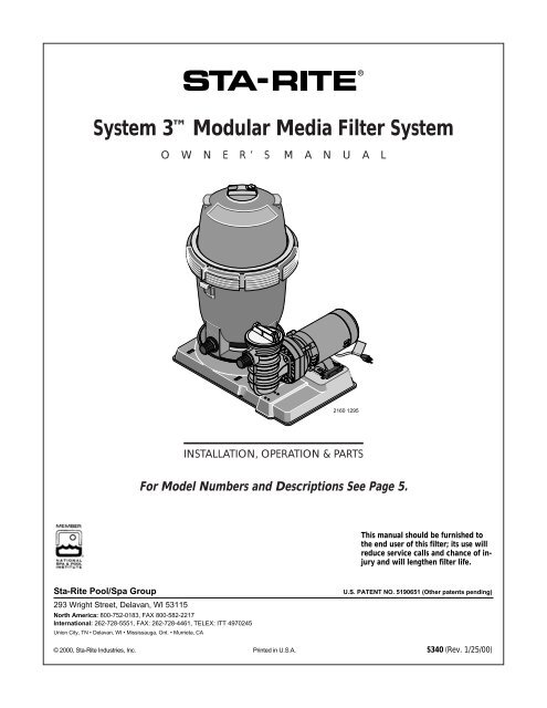
REPAIR PARTS LIST<br />
<strong>Modular</strong> <strong>Media</strong> <strong>Filter</strong> <strong>System</strong>s<br />
See Page 15 for <strong>Filter</strong> Tank Assembly Parts<br />
See Pages 16 and 17 for Pump Parts<br />
6<br />
5<br />
8<br />
OUTLET<br />
INLET<br />
2<br />
3<br />
4<br />
7<br />
6<br />
5<br />
2159 1295<br />
REPAIR PARTS LIST – <strong>Modular</strong> <strong>Media</strong> <strong>System</strong><br />
Model No.<br />
PLM100JWAE-03 PLM100JWAF-03 PLM150JWAE-03 PLM150JWAF-03<br />
PLM100JWAE-04 PLM100JWAF-04 PLM150JWAE-04 PLM150JWAF-04<br />
PLM100JWAE-06 PLM100JWAF-06 PLM150JWAE-06 PLM150JWAF-06<br />
Key Part PLM100JWAE-12 PLM100JWAF-12 PLM150JWAE-12 PLM150JWAF-12<br />
No. Description Qty. 1 HP 1-1/2 HP 1 HP 1-1/2 HP<br />
1 <strong>Filter</strong> Tank Assembly 1 PLM100 PLM100 PLM150 PLM150<br />
2 Union Half Assembly 1 27001-0120 27001-0120 27001-0120 27001-0120<br />
3 O-Ring 1 U9-226 U9-226 U9-226 U9-226<br />
4 Pump Assembly (-03, -04 Models) 1 JWPA5E7L-2A2 JWPA5F7L-2A2 JWPA5E7L-A2 JWPA5F7L-2A2<br />
4 Pump Assembly (-06 Models) 1 JWPA5E7C-2A3U JWPS5F7C-2A3U JWPA5E7C-2A3U JWPS5F7C-2A3U<br />
4 Pump Assembly (-12 Models) 1 JWPA5E7L-2A1 JWPA5F7L-2A1 JWPA5E7L-2A1 JWPA5F7L-2A1<br />
4 Pump Assembly (-15 Models) 1 – JWPA5YF7L-A1 – –<br />
• Adapter Kit (includes Key No. 6, 7) 1 27001-0141 27001-0141 27001-0141 27001-0141<br />
5 Hose Adapter 1-1/2” MPT Male 2 11201-0002 11201-0002 11201-0002 11201-0002<br />
6 Hose Clamp 4 P19-30 P19-30 P19-30 P19-30<br />
7 Platform Base 1 27001-0031 27001-0031 27001-0031 27001-0031<br />
8 2” NPT x 1-1/2” NPT Reducer Bushing 1 U78-820P U78-820P U78-820P U78-820P<br />
• <strong>System</strong> Nameplate 1 27002-0045 27002-0045 27002-0045 27002-0045<br />
• Hose Assembly 1-1/2” X 77” (-03 Models only) 2 34055-7038 34055-7038 34055-7038 34055-7038<br />
• Platform Extension (Optional) 1 27001-0032 27001-0032 27001-0032 27001-0032<br />
• Not illustrated.<br />
15
REPAIR PARTS<br />
<strong>Filter</strong> Tank Assembly<br />
11<br />
Key<br />
Part<br />
No. Description Qty. Number<br />
6<br />
7A<br />
1<br />
2<br />
3<br />
4<br />
5<br />
RELEASE<br />
7B<br />
8<br />
OUTLET<br />
9<br />
10<br />
10A<br />
DRAIN<br />
12<br />
Base rotated 90° to show<br />
check valve installed.<br />
13<br />
1 Posi-Lok ring* 1 27001-0050B<br />
2 Air release valve assembly 1 25010-0200<br />
3 Tank shell upper half* 1 27001-0020S<br />
4 Tank O-ring 1 27001-0061S<br />
5 Tank shell lower half 1 27001-0009S<br />
6 Safety latch for ring 1 27001-0051<br />
7A 1-1/2” NPT plug 1 11201-0005B<br />
7B Adapter fitting 1 24900-0509<br />
8 O-ring 1 35505-1424<br />
9 2” x 1-1/2” Pipe reducer*** 2 U78-820P<br />
10 Pressure gauge*** 1 15060-0000T<br />
10A Pressure gauge screen*** 1 WC8-72D<br />
11 Air bleed assembly 1 24800-0121<br />
12 <strong>Filter</strong> module (PLM100) 1 27002-0100S<br />
12 <strong>Filter</strong> module (PLM150) 1 27002-0150S<br />
13 Spring check valve** 1 27001-0130S<br />
• Accessory package 1 27001-0140<br />
• Decal, logo 1 27001-0041<br />
• Decal, warning 1 27001-0042<br />
• Decal, operating instr. 1 27002-0043<br />
• Decal, nameplate (PLM100) 1 27002-0042<br />
• Decal, nameplate (PLM150) 1 27002-0045<br />
• Owner’s manual 1 S340<br />
• Teflon tape*** 1 U97-58<br />
• O-ring grease*** 1 34725-0013<br />
• Not illustrated.<br />
* Includes all decals and labels.<br />
** Optional equipment.<br />
*** Shipped in accessory package.<br />
16
1<br />
2<br />
3 4<br />
5<br />
REPAIR PARTS LIST — 17290 SERIES PUMPS<br />
See Pump nameplate for Pump Model Number<br />
for <strong>Filter</strong> <strong>System</strong> with Suffix -06<br />
6<br />
7<br />
8<br />
9<br />
10<br />
16<br />
15<br />
11<br />
12<br />
14<br />
13<br />
17<br />
18<br />
19<br />
Key<br />
Part<br />
No. Description Qty. Number<br />
1 End Cap Screw 3 37337-0085<br />
2 Cap and Cord Ass’y 1 Chart at Right<br />
3 Toggle Switch 1 16920-0511<br />
4 Toggle Switch Boot 1 32800-0107<br />
5 Baffle Ring 1 17290-0004<br />
6 Motor 1 Chart at Right<br />
7 Flinger 1 C69-2<br />
8 Motor Cover 1 17190-0021<br />
9 Seal Plate 1 17301-0150<br />
10 Shaft Seal 1 U9-358SS<br />
11 Impeller 1 Chart at Right<br />
12 O-Ring 1 U9-357<br />
13 Front Plate 1 C101-272P<br />
14 Plain Washer 4 U43-60SS<br />
15 Lock Washer 4 U43-10SS<br />
16 Cap Screw 4 U30-873SS<br />
17 Trap Lid 1 C3-139P1<br />
18 Trap Lid O-Ring 1 U9-229<br />
19 Trap Basket 1 C108-33P<br />
20 Trap Body 1 C153-53P<br />
21 Drain Plug w/O-Ring 2 U178-920P<br />
22 Cap Screw 4 U30-64SS<br />
23 Lock Washer 4 U43-11SS<br />
24 Plain Washer 4 U43-41SS<br />
25 Trap Outlet Gasket 1 C20-123<br />
26 Mounting Foot 1 17190-0023<br />
• Nameplate 1 32155-4073<br />
• Decal – GFCI Required 1 U27-558<br />
• Tag – Do Not Use Pipe Dope 1 61002-0002<br />
• Tag – Electrical, priming 1 61002-0004<br />
21<br />
25<br />
24<br />
23<br />
22<br />
806 0394<br />
Parts are common to all models listed except as noted;<br />
Key Nos. 6, Motor; and 11, Impeller, are listed below.<br />
Motor No. Impeller No.<br />
Model No.HP (Key No. 6) (Key No. 11)<br />
115V/60/1<br />
JWPA5E7C-2A3 1 AS901EL C105-228PWS<br />
JWPS5F7C-2A3 1-1⁄2SPL AS901SFL C105-228PWS<br />
Model No. HP Cord & Cap Assembly<br />
115V/60/1<br />
JWPA5E7C-2A3 1 17190-0026-S<br />
JWPS5F7C-2A3 1-1/2SPL 17190-0026-S<br />
Trap Cover/O-Ring Kit (5” Trap)<br />
Kit includes C3-139P1 Trap Cover and U9-229 O-Ring.<br />
Parts-Pak No. PP2075.<br />
21<br />
20<br />
17
2A<br />
2<br />
6<br />
REPAIR PARTS LIST — JWA Series PUMPS<br />
See Pump nameplate for Pump Model Number<br />
for <strong>Filter</strong> <strong>System</strong> with Suffix -03, -04, -12, or -15<br />
7<br />
9<br />
17<br />
10<br />
11<br />
12<br />
18<br />
13<br />
19<br />
Cord and Plug Part Numbers<br />
14<br />
15<br />
16<br />
-A1 and -2A1 Models -2A2 Models<br />
HP Cord Ass’y with Cord Ass’y with<br />
Twist-lock Plug Straight Plug<br />
20<br />
1 31953-0101 U117-1117<br />
1-1/2 31953-0101 U117-1118<br />
13A<br />
21<br />
25<br />
Model Number<br />
JWPA5YF7L-A1<br />
JWPA5E7L-2A1 JWPA5F7L-2A1<br />
Key JWPA5E7L-2A2 JWPA5F7L-2A2<br />
No. Description Qty. 1 HP 1-1/2 HP<br />
2 Motor End Cap 1 Not Available separately<br />
2A Cord Assembly 1 See Chart See Chart<br />
6 Motor 115/60H/1Ph (Without Cord)* 1 AS920ELL AS920FLL<br />
7 Slinger 1 C69-23 C69-23<br />
9 Seal Plate 1 C1-260P C1-260P<br />
10 Seal 1 U109-358SS U109-358SS<br />
11 Impeller 1 C105-228PG 17301-0101<br />
12 O-Ring 1 U9-357 U9-357<br />
13 Front Plate 1 C101-272P C101-272P<br />
13A Pipe Plug 2 WC78-40T WC78-40T<br />
14 Washer, 1/4 Flat 6 U43-117SS U43-117SS<br />
15 Washer, 1/4 Lock 6 U43-10SS U43-10SS<br />
16 Screw, 1/4-20x1-3/4 6 U30-873SS U30-873SS<br />
17 Trap Cover 1 C3-139P1 C3-139P1<br />
18 O-Ring - Cover 1 U9-229 U9-229<br />
19 Strainer Basket 1 C108-33P C108-33P<br />
20 Trap Body 1 C153-53P1 C153-53P1<br />
21 Drain Plug - 1/4” NPT (w/O-Ring) 2 U178-920P U178-920P<br />
22 Capscrew 5/16-18x1-1/4” 4 U30-64SS U30-64SS<br />
23 Washer, Lock 5/16” 4 U43-11SS U43-11SS<br />
24 Washer, Flat 5/16” 4 U43-41SS U43-41SS<br />
25 Gasket 1 C20-123 C20-123<br />
• Nameplate 1 U33-155 U33-155<br />
• Decal “Tested for Pools & Spas” 1 U27-635 U27-635<br />
• Decal - GFCI required 1 U27-558 U27-558<br />
• Decal - Caution 1 32165-4038 32165-4038<br />
• Tag - bonding instructions 1 C63-12 C63-12<br />
• Tag - CAUTION Securely 1 61002-0002 61002-0002<br />
Tighten…Warning…<br />
24<br />
23<br />
22<br />
2248 0196<br />
21<br />
Trap Cover/O-Ring Kit (5” Trap)<br />
Kit includes C3-139P1 Trap Cover and<br />
U9-229 O-Ring.<br />
Parts-Pak No. PP2075.<br />
• Not illustrated.<br />
* Model JWPA5YF7L-A1 uses Part No. 62003-2032.<br />
18
STA-RITE LIMITED WARRANTY<br />
Pumps, filters, skimmers, underwater lights (except bulbs),<br />
accessories and fittings manufactured by Sta-Rite are warranted<br />
to be free of defects in material and workmanship for<br />
one (1) year from date of installation.<br />
Product specific warranties:<br />
Year from date<br />
of installation<br />
HRPB, DEPB and <strong>System</strong> 3 – Tanks . . . . . . . . . . . .10 years<br />
Internal filter components and valves . . . . . . . . . 1 year<br />
Max-E-Therm – Pool/Spa Heaters . . . . . . . . . . . . . 2 years<br />
Heater Enclosure only (Upper RH & LH;<br />
lower enclosure; and control board enclosure)… 10 years<br />
Automatic Pool Cleaners including Hose . . . . . . . 2 years<br />
Cristal-Flo filters – Tanks . . . . . . . . . . . .10 years pro-rated*<br />
Valve and internal components. . . . . . . . . . . . . . . . 1 year<br />
Posi-Flo II – Tanks . . . . . . . . . . . . . . . . . . . . . . . . . .10 years<br />
Elements . . . . . . . . . . . . . . . . . . . . . . . . . . . . . . . . 1 year<br />
Waterford Sand – Tanks . . . . . . . . . . . . .10 years pro-rated*<br />
Pumps . . . . . . . . . . . . . . . . . . . . . . . . . . . . . . . . . . 1 year<br />
Valve and Internals . . . . . . . . . . . . . . . . . . . . . . . . . 1 year<br />
Waterford Cartridge – <strong>Filter</strong> Tank . . . . . . . . . . . . .10 years<br />
Pumps . . . . . . . . . . . . . . . . . . . . . . . . . . . . . . . . . . 1 year<br />
<strong>System</strong> 3 Above Ground <strong>System</strong>s – Tanks . . . . . . .10 years<br />
Pumps . . . . . . . . . . . . . . . . . . . . . . . . . . . . . . . . . . 1 year<br />
Platform and Internals . . . . . . . . . . . . . . . . . . . . . . 1 year<br />
Pumps . . . . . . . . . . . . . . . . . . . . . . . . . . . . . . . . . . . . . 1 year<br />
When equipped with A.O. Smith<br />
2-compartment motors (Does not include<br />
pumps sold as part of a systems package) . . . . . . 2 years<br />
* Full warranty coverage is in effect for one year after installation.<br />
The pro-rated warranty covers the tank only during<br />
the 2nd through 10th year after installation. The amount covered<br />
decreases by 10% each year. (ie., 2nd year 90% covered,<br />
3rd year 80% covered, etc.).<br />
The foregoing warranties relate to the original consumer purchaser<br />
(“Purchaser”) only. Sta-Rite shall have the option to repair<br />
or replace the defective product, at its sole discretion.<br />
Purchasers must pay all labor and shipping charges necessary<br />
to replace the product covered by this warranty.<br />
Requests for warranty service must be made through the installing<br />
dealer. This warranty shall not apply to any product<br />
that has been subject to negligence, misapplication, improper<br />
installation or maintenance, or other circumstances<br />
which are not in Sta-Rite’s direct control.<br />
This warranty sets forth Sta-Rite’s sole obligation and<br />
Purchaser’s exclusive remedy for defective products.<br />
STA-RITE SHALL NOT BE LIABLE FOR ANY CONSEQUEN-<br />
TIAL, INCIDENTAL OR CONTINGENT DAMAGES WHATSO-<br />
EVER.<br />
THE FOREGOING WARRANTIES ARE EXCLUSIVE AND IN<br />
LIEU OF ALL OTHER EXPRESS WARRANTIES. IMPLIED WAR-<br />
RANTIES, INCLUDING BUT NOT LIMITED TO THE IMPLIED<br />
WARRANTIES OF MERCHANTABILITY AND FITNESS FOR A<br />
PARTICULAR PURPOSE, SHALL NOT EXTEND BEYOND THE<br />
DURATION OF THE APPLICABLE EXPRESS WARRANTIES<br />
PROVIDED HEREIN.<br />
Some states do not allow the exclusion or limitation of incidental<br />
or consequential damages or limitations on how long<br />
an implied warranty lasts, so the above limitations or exclusion<br />
may not apply to you. This warranty gives you specific<br />
legal rights and you may also have other rights which vary<br />
from state to state.<br />
Supersedes all previous publications.<br />
Sta-Rite Industries, Inc.<br />
293 Wright Street<br />
Delavan, WI 53115<br />
▲ Retain Warranty Certificate (upper portion) in a safe and convenient location for your records.<br />
DETACH HERE: Fill out bottom portion completely and mail within 10 days of purchase/installation to:<br />
▼ Sta-Rite, Attn: Warranty Dept., 293 Wright St., Delavan, WI 53115<br />
Warranty Registration Card<br />
Name<br />
Address<br />
City State Zip<br />
Purchase Date<br />
Years pool has been in service ■ less than 1 ■ 1-3 ■ 3-5 ■ 5-10<br />
Purchased from:<br />
Company name<br />
Address<br />
City State Zip<br />
Product Purchased<br />
■ New installation<br />
■ Replacement<br />
Please send me more information on these<br />
other products from Sta-Rite.<br />
Type of Pool ■ Inground ■ Vinyl ■ Fiberglass ■ Gunite<br />
Size of Pool<br />
■ Pumps ■ <strong>Filter</strong>s ■ Automatic Pool Cleaners<br />
■ Maintenance Equipment ■ Test Strips<br />
■ Heaters<br />
S4877PS (2/20/98)