Road Drainage (PDF 473 kB) - Land for Wildlife
Road Drainage (PDF 473 kB) - Land for Wildlife
Road Drainage (PDF 473 kB) - Land for Wildlife

Create successful ePaper yourself
Turn your PDF publications into a flip-book with our unique Google optimized e-Paper software.
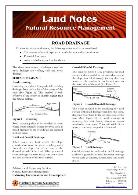
ROAD DRAINAGE<br />
To allow <strong>for</strong> adequate drainage, the following points need to be considered:<br />
• The amount of runoff expected to reach the area under consideration.<br />
• Potential flood areas.<br />
• Areas of discharge, such as floodways.<br />
The three components of adequate road or<br />
track drainage are surface, side and cross<br />
drainage.<br />
SURFACE DRAINAGE<br />
<strong>Road</strong> crowning<br />
Crowning provides a low-grade fall enabling<br />
drainage from both sides of the centre of the<br />
road (See Figure 1). This method is only<br />
effective if the crown is slightly higher than<br />
the natural surface.<br />
Figure 1 Crowning<br />
<strong>Road</strong> crowning should be avoided in areas<br />
where water naturally crosses the road such as<br />
broad drainage floors. Floodways are required<br />
in these cases.<br />
Infall and Outfall <strong>Drainage</strong><br />
When roads are built across the slope<br />
consideration must be given to taking water<br />
from the up slope side of the road to the<br />
down slope side of the road. When you install<br />
cross drainage you must make sure that it does<br />
not cause erosion of the road surface.<br />
Crossfall/Outfall <strong>Drainage</strong><br />
The simplest method is by providing the road<br />
surface with a crossfall in the same direction as<br />
the slope (outfall drainage), thereby directing<br />
water over the road surface to disposal areas on<br />
the lower side of the road (See Figure 2).<br />
Figure 2 Crossfall/outfall drainage<br />
The other method is by providing the road<br />
surface with infall drainage back into the slope,<br />
directing water back to the up slope side of the<br />
road (See Figure 3). If infall drainage is<br />
necessary then table drains, culverts or inverts<br />
need to be constructed. These will safely direct<br />
water to the down slope side of the road.<br />
Figure 3 Infall drainage<br />
Outfall drainage is preferred to infall drainage<br />
as there is generally no need <strong>for</strong> other drainage<br />
works such as culverts, inverts, table and mitre<br />
drains.<br />
Advisory and Regulatory Services<br />
Natural Resource Management<br />
Balancing Conservation and Development<br />
PO Box 1120<br />
Alice Springs, NT 0871<br />
Alice Plaza, Level 1<br />
Todd Mall<br />
Alice Springs, NT 0870<br />
Telephone: 8951 9208<br />
Fax: 8951 9222<br />
http://www.nreta.nt.gov.au/advis/
When installing outfall drainage on steeper<br />
slopes, batters on the downslope side of the<br />
road must not be too steep. Steep batters may<br />
erode, impacting on the road itself.<br />
The crossfall of the road surface should be<br />
kept as flat as possible to ensure good<br />
drainage. For outfall drainage it is<br />
recommended that the maximum crossfall<br />
slope be in the order of 1.5 – 2%, whereas<br />
infall drainage slopes can be as great as 4%.<br />
SIDE DRAINAGE<br />
Table drains<br />
Table drains are excavated open channels that<br />
are built parallel to roads and tracks. These<br />
drains direct runoff to disposal areas further<br />
downslope. Table drains should only be used<br />
when natural run-off is not possible.<br />
Fill obtained from constructing table drains<br />
can be used to build up road surfaces.<br />
The design of table drains depends on a<br />
number of factors, including the size and<br />
nature of the catchment, the slope and water<br />
volumes and flow. Larger table drains may<br />
need to be designed by engineers or soil<br />
conservation officers.<br />
Table drains should be constructed with a flat<br />
bottom (trapezoid shape) (See Figure 4). In<br />
general they should be 0.5 to 1.0m wide at the<br />
base. Avoid using V shaped drains as they<br />
may cause erosion in the channel.<br />
Where possible table drains should be<br />
revegetated as soon as possible after<br />
construction, and regularly slashed. Table<br />
drains should not be graded.<br />
Figure 4 Table & mitre drain cross section<br />
Mitre drains<br />
Water should be taken out of table drains at<br />
regular intervals using mitre (offshoot) drains.<br />
Mitre drains take runoff out of table drains,<br />
or directly off road shoulders where table<br />
drains are absent. These drains dispose of<br />
water in areas away from the road (See<br />
Figure 5).<br />
Figure 5<br />
Crowned road with only mitre drains<br />
Figure 6 Crowned road with table & mitre<br />
drains<br />
Mitre drains stop water accumulating in table drains<br />
or on the road shoulder. Ideally mitre drains should<br />
be constructed so that they have a broad flat base at<br />
least 1m wide. Mitre drains also should not be<br />
graded to produce a V.<br />
Mitre drains should slope to direct the flow of water<br />
away from the road. To minimise erosion the slope<br />
should be no greater than 0.5% on erodable soils or<br />
1% on stable soils. Mitre drain outlets effectively<br />
concentrate runoff, <strong>for</strong> this reason they should be<br />
located in stable undisturbed areas.<br />
• Mitre drain spacing is dependent on:<br />
• The grade of the table drain or road<br />
• soil type and erodability<br />
• rainfall.<br />
Table 1 Recommended Mitre drain spacing<br />
Slope<br />
% Gradient<br />
Mitre Drain Spacing (m)<br />
0.5 1 : 200 170 - 180<br />
1 1 : 100 120 - 130<br />
2 1 : 50 90 - 100<br />
3 1 : 33 70 - 80<br />
4 1 : 25 60 - 70<br />
5 1 : 20 55 - 60<br />
6 1 : 17 50 - 55<br />
10 1 : 10 40 - 45<br />
2
CROSS DRAINAGE<br />
Engineered, stable cross drainage such as<br />
inverts, floodways or culverts can be used to<br />
collect water from upslope table drains, or<br />
drainage lines.<br />
It is generally more economical and practical to<br />
<strong>for</strong>d drainage lines using floodways or inverts<br />
than to use major culverts or bridges. On<br />
steeper country, where creeks and drainage lines<br />
are deeper, culverts may be more practical.<br />
Inverts and floodways<br />
Care must be taken in the design and<br />
construction of floodways and inverts in order<br />
to cause minimal interference to natural flows.<br />
Inverts and floodways are designed to be<br />
temporarily over topped by water flow.<br />
minimise bank and bed erosion. They should be<br />
sited at low points in the bank and at right<br />
angles to the direction of flow.<br />
Inverts<br />
Inverts should be constructed with the finished<br />
surface at, or just below the level of the existing<br />
stream bed.<br />
Construction of an invert is generally based on<br />
excavating soft, erodable material. At least<br />
300mm should be removed, geotextile may be<br />
necessary as a base. Excavated material is then<br />
replaced with compacted granular material to<br />
provide a trafficable surface (See Figure 7).<br />
Figure 7<br />
Inverts<br />
Floodways<br />
Floodways are usually elevated above the bed<br />
level of the channel and often incorporate<br />
culverts to take “normal” flows with the road<br />
only being overtopped during flood events, as<br />
illustrated in Figure 8.<br />
Figure 8 Floodways (Source: Australian<br />
<strong>Road</strong> Research Board, 1993)<br />
The design should have ends of the structure<br />
that are well anchored into the banks and<br />
obstruction to flow kept to a minimum by<br />
using gentle batter slopes on the up- and<br />
downstream faces. When it is necessary to<br />
construct an elevated floodway it is<br />
recommended that specialist advice be sought.<br />
As floodways are generally elevated above bed<br />
level protection works are required on the<br />
downstream side of the floodway to prevent<br />
erosion.<br />
CULVERTS<br />
When culverts are used they should be angled<br />
downward at between 1 and 3%. This will<br />
minimise silting of the pipe and prevent<br />
excessive scouring at the outflow.<br />
On drainage lines the culvert should be keyed<br />
into the streambed by digging a trench and<br />
seating the culvert into it.<br />
The area below the outlet will need protection<br />
to prevent erosion. This protection can be<br />
achieved by armouring (eg: rock mattress) the<br />
drain downstream of the outlet, or by<br />
constructing a dissipating device (see Figure 9).<br />
Protection may also be required at the inlet.<br />
The location, spacing, size and type of culvert<br />
may vary. Advice should be sought from Soil<br />
Conservation Officers prior to construction.<br />
3
2. Using imported soil material to construct a<br />
bank with a grade of between 0.3 and 0.5%<br />
along the up slope edge of the bank.<br />
To aid trafficability, an approach and departure<br />
ramp can be cut into the bank (See Figure 2).<br />
The bank should be run off into undisturbed<br />
vegetation or into an existing drain (care needs to<br />
taken to ensure that erosion does not occur<br />
where the water runs down into the drain).<br />
Alternatively a level sill can be constructed at the<br />
end of the bank to enhance the spread of water.<br />
Figure 9 Culverts<br />
WHOA BOYS ON VEHICLE TRACKS<br />
Whoa boys can vary in size. They can be a<br />
couple of metres long and only 10–30cm<br />
high on walking tracks, or they may be large,<br />
gently sloping banks up to 30-40m and up to<br />
3m high on deeply eroded areas.<br />
Whoa boys can be constructed in two ways:<br />
1. By cut and fill –Lines are ripped across<br />
the area at a grade of 0.3 %. A shallow<br />
channel should be cut along this line.<br />
Excavated material is dumped on the<br />
down slope side of the channel, then<br />
compacted and smoothed out to <strong>for</strong>m a<br />
bank with even batters and a level top<br />
(See Figure 1).<br />
Figure 1<br />
Figure 2<br />
Whoa boy construction<br />
Whoa boy – vehicle track<br />
For further in<strong>for</strong>mation about controlling erosion in the southern region of the<br />
NT contact Advisory and Regulatory Services or visit our website<br />
www.nreta.nt.gov.au/advis/land/soils.htm<br />
4