D-4990 Low Energy Operator Installation Guide - Precision Hardware
D-4990 Low Energy Operator Installation Guide - Precision Hardware
D-4990 Low Energy Operator Installation Guide - Precision Hardware

Create successful ePaper yourself
Turn your PDF publications into a flip-book with our unique Google optimized e-Paper software.
Copyright © 2007 Stanley Security Solutions, Inc. and Stanley<br />
Logistics, Inc. All rights reserved. Printed in the United States of<br />
America.<br />
Information in this document is subject to change without notice<br />
and does not represent a commitment on the part of<br />
Stanley Security Solutions, Inc. The software described in this<br />
document is furnished under a license agreement or nondisclosure<br />
agreement.<br />
This publication is intended to be an accurate description and set of<br />
instructions pertaining to its subject matter. However, as with any<br />
publication of this complexity, errors or omissions are possible.<br />
Please call Stanley Security Solutions, Inc., at (317) 849-2250 if you<br />
see any errors or have any questions. No part of this manual and/or<br />
databases may be reproduced or transmitted in any form or by any<br />
means, electronic or mechanical, including photocopying,<br />
recording, or information storage and retrieval systems, for any<br />
purpose, without the express written permission of Stanley Security<br />
Solutions, Inc.<br />
This document is distributed as is, without warranty of any kind,<br />
either express or implied, respecting the contents of this book,<br />
including but not limited to implied warranties for the publication’s<br />
quality, performance, merchantability, or fitness for any particular<br />
purpose. Neither Stanley Security Solutions, Inc., nor its dealers or<br />
distributors shall be liable to the user or any other person or entity<br />
with respect to any liability, loss, or damage caused or alleged to be<br />
caused directly or indirectly by this publication.<br />
Written and designed by Stanley Security Solutions, Inc.,<br />
Indianapolis, Indiana.<br />
05131-11 Rev – ER7991-12 July 2007
CONTENTS<br />
1 CONTENTS<br />
1 INSTALLING THE D-<strong>4990</strong><br />
LOW ENERGY OPERATOR<br />
Introduction and benefits 1<br />
Component/<br />
block diagram 2<br />
Cautions 3<br />
Product support & service contacts 3<br />
<strong>Installation</strong> overview 3<br />
Typical application riser diagrams & wiring diagrams 4<br />
Task 1: Prepare the installation 1–9<br />
Minimum installation requirements 9<br />
<strong>Installation</strong> tools required 9<br />
Task 2: Mount the operator 1–11<br />
Task 3: Mount the push plates or other actuators 1–15<br />
Task 4: Attach arms 1–15<br />
Task 5: Make electrical connections 1–17<br />
Task 6: Make initial settings and adjustments 1–21<br />
Checklist before turning on power 21<br />
Turn on power 21<br />
D-<strong>4990</strong> <strong>Low</strong> <strong>Energy</strong> <strong>Operator</strong> <strong>Installation</strong> & User <strong>Guide</strong> ii
Contents<br />
Door cycle stages 22<br />
Check force and Kinetic energy 24<br />
Potentiometers 24<br />
Digital readout 26<br />
DIP switch settings 26<br />
Task 7: Complete the installation 1–28<br />
Applying decals 28<br />
Safety checks 1–29<br />
2 IMPORTANT<br />
TERMS<br />
iii<br />
D-<strong>4990</strong> <strong>Low</strong> <strong>Energy</strong> <strong>Operator</strong> <strong>Installation</strong> & User <strong>Guide</strong>
1 INSTALLING THE D-<strong>4990</strong><br />
LOW ENERGY OPERATOR<br />
Introduction<br />
and benefits<br />
The <strong>Precision</strong> heavy-duty D-<strong>4990</strong> <strong>Low</strong> <strong>Energy</strong> <strong>Operator</strong> is an electro-mechanical<br />
product designed to provide safe and convenient automatic access to elderly or<br />
physically impaired persons who require additional assistance.<br />
Product features include:<br />
■<br />
■<br />
■<br />
■<br />
■<br />
■<br />
■<br />
■<br />
Because this is a ‘low energy’ operator, no guide rails or safety mats are<br />
required.<br />
Operates quietly, safely, conveniently, and reliably<br />
Electrically swings open up to 90 degrees<br />
Manually swings open up to 120 degrees on pull-side installations; and up to<br />
180 degrees on push-side installations.<br />
Acts as a standard door closer in the event of a power failure<br />
Complies with Americans with Disabilities Act Title 3 (ADA) requirements<br />
Allows independent adjustment for<br />
▲ door opening speed<br />
▲ door opening force<br />
▲ hold-open time up to 30 seconds<br />
Complies with:<br />
▲ UL Listed for use on fire and smoke check doors<br />
▲ UL 325 Standard for Door, Drapery, Gate, Louver, and Window <strong>Operator</strong>s<br />
and Systems.<br />
▲ UL 228 Standard for Door Closers-Holders, with or without Integral Smoke<br />
Detectors<br />
▲ Meets requirements for UL 10C and UBC 7.2 for positive pressure<br />
▲ Complies with Americans with Disabilities Act (ADA)<br />
D-<strong>4990</strong> <strong>Low</strong> <strong>Energy</strong> <strong>Operator</strong> <strong>Installation</strong> <strong>Guide</strong> 1–1
Installing the D-<strong>4990</strong> low energy operator<br />
■<br />
■<br />
▲ ANSI/BHMA 156.19 certified standard for Power Assist and <strong>Low</strong> <strong>Energy</strong><br />
Power-Operated Doors<br />
▲ Complies with ANSI 117.1 section 4.13<br />
▲ In compliance with FCC 47 CFR part 15 class B emissions requirements<br />
(USA)<br />
Monitors for obstructions during the opening cycle, ensuring safe access.<br />
Closes either with the built-in D-4550 hydraulic closer or with the added help<br />
of the built-in motor. This feature – power close – is especially helpful in<br />
windy conditions or in buildings where interior stack pressures build up. This<br />
feature can reduce energy use and cost.<br />
Component/<br />
block diagram<br />
For a view of the entire D-<strong>4990</strong> system and the relationships between<br />
components, see the diagram below. Shaded objects can be used in the system,<br />
but are optional for the system to work. Non-shaded items are required.<br />
120VAC Power<br />
Source<br />
D-<strong>4990</strong> <strong>Low</strong> <strong>Energy</strong><br />
<strong>Operator</strong><br />
Access control<br />
system<br />
Door<br />
Actuators<br />
Types of actuators:<br />
• Wired push button<br />
• Wireless push button<br />
• Card access<br />
Fire alarm panel<br />
Electric lock<br />
Power supply<br />
for lock<br />
Figure 1.1<br />
Types of locks:<br />
• ELR (electric latch retraction) exit devices<br />
• Magnetic locks<br />
• Electric strike<br />
Block diagram showing the relationships to the components in the system.<br />
Shaded components are optional. Non-shaded components are required.<br />
1–2 D-<strong>4990</strong> <strong>Low</strong> <strong>Energy</strong> <strong>Operator</strong> <strong>Installation</strong> <strong>Guide</strong>
Cautions<br />
Product<br />
support &<br />
service<br />
contacts<br />
<strong>Installation</strong><br />
overview<br />
Installing the D-<strong>4990</strong> low energy operator<br />
Improper installation or regulation or adjustment may result in personal injury or<br />
property damage. Follow this instruction manual carefully.<br />
For product support contact your Stanley <strong>Precision</strong> factory representative.<br />
Use this installation overview to help you prepare for all the stages of the<br />
installation. Follow the cross-reference pages to get the full details of that step.<br />
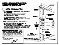
1 Prepare the installation – Make sure that the door opening is fully ready to<br />
receive the D-<strong>4990</strong> Power <strong>Operator</strong>, including power source and control wiring<br />
for the operator. See Task 1: Prepare the installation on page 1-9.<br />
2 Install the operator – Install the operator to the door header. See Task 2: Mount<br />
the operator on page 1-11.<br />
3 Install the actuators – Install the push plate, card readers or other actuators. See<br />
Task 3: Mount the push plates or other actuators on page 1-15.<br />
4 Install the operator arms – Install the arms to the door operator and door. See<br />
Task 4: Attach arms on page 1-15.<br />
5 Make all wiring connections – Make all power, switch, and output lock device<br />
wiring connections. See Task 5: Make electrical connections on page 1-17.<br />
6 Make initial settings and adjustments – Set switches and make adjustments for<br />
backcheck, closer speed, power close, hold open, door speed, door force, etc.<br />
See Task 6: Make initial settings and adjustments on page 1-21.<br />
7 Complete the installation – Finalize the installation with testing, troubleshooting,<br />
applying decals, and final inspections. See Task 7: Complete the installation on<br />
page 1-28.<br />
D-<strong>4990</strong> <strong>Low</strong> <strong>Energy</strong> <strong>Operator</strong> <strong>Installation</strong> <strong>Guide</strong> 1–3
Installing the D-<strong>4990</strong> low energy operator<br />
Typical<br />
application<br />
riser diagrams<br />
& wiring<br />
diagrams<br />
Simple door operator with inside and outside actuators<br />
■ Doors locked during off hours with mechanical lock only.<br />
■ One actuator switch operates the door from the outside.<br />
■ A second actuator switch operates the door from the inside.<br />
120VAC<br />
<strong>Operator</strong><br />
Actuator<br />
inside<br />
Actuator<br />
outside<br />
Figure 1.2 Riser diagram showing a single door with an operator and no electric locking<br />
device.<br />
Use the following diagram to wire this application.<br />
Actuator<br />
outside<br />
Actuator<br />
inside<br />
NO<br />
Com<br />
NO<br />
Com<br />
Door control<br />
1<br />
2<br />
3<br />
4<br />
TB1<br />
Figure 1.3<br />
Wiring diagram for simple single door installation<br />
1–4 D-<strong>4990</strong> <strong>Low</strong> <strong>Energy</strong> <strong>Operator</strong> <strong>Installation</strong> <strong>Guide</strong>
Installing the D-<strong>4990</strong> low energy operator<br />
Simple door operator with electric strike and inside and outside actuators<br />
■<br />
■<br />
■<br />
Doors locked with electric strike.<br />
One actuator switch operates the door from the outside.<br />
A second actuator switch operates the door from the inside.<br />
120VAC<br />
<strong>Operator</strong><br />
Electric<br />
strike<br />
Actuator<br />
inside<br />
Actuator<br />
outside<br />
Figure 1.4 Riser diagram showing a single door with an operator and no electric locking<br />
device.<br />
Use the following diagram to wire this application.<br />
D-<strong>4990</strong> <strong>Low</strong> <strong>Energy</strong> <strong>Operator</strong> <strong>Installation</strong> <strong>Guide</strong> 1–5
Installing the D-<strong>4990</strong> low energy operator<br />
Actuator<br />
outside<br />
Actuator<br />
inside<br />
NO<br />
Com<br />
NO<br />
Com<br />
Door control<br />
1<br />
2<br />
3<br />
4<br />
TB1<br />
Figure 1.5<br />
Optional +<br />
power –<br />
supply<br />
(DC only)<br />
PS490-12 or<br />
PS490-24<br />
8<br />
9<br />
10<br />
TB2<br />
Wiring diagram for simple single door installation<br />
+<br />
–<br />
Electric<br />
strike (by others)<br />
1–6 D-<strong>4990</strong> <strong>Low</strong> <strong>Energy</strong> <strong>Operator</strong> <strong>Installation</strong> <strong>Guide</strong>
Installing the D-<strong>4990</strong> low energy operator<br />
Vestibule — Two single doors and operators with electric latch retraction<br />
■<br />
■<br />
■<br />
■<br />
Doors closed and latched at all times<br />
When activated, latchbolts retract and doors automatically open<br />
Two actuators outside of the vestibule operates the closest door first, then<br />
second<br />
One activator inside of the vestibule operates the closest door only.<br />
120VAC<br />
Power<br />
supply<br />
(by others)<br />
<strong>Operator</strong><br />
<strong>Operator</strong><br />
Actuator<br />
Actuators<br />
ELR Exit Device<br />
Actuator<br />
Figure 1.6 Riser diagram showing a vestibule having two single doors with operators and<br />
electric latch retraction exit devices<br />
To wire the vestibule of this installation see See Figure 1.7 on page 1-8.<br />
D-<strong>4990</strong> <strong>Low</strong> <strong>Energy</strong> <strong>Operator</strong> <strong>Installation</strong> <strong>Guide</strong> 1–7
Installing the D-<strong>4990</strong> low energy operator<br />
Actuator outside<br />
NO<br />
Com<br />
Door 1 control<br />
1<br />
2<br />
NO<br />
Inner vestibule<br />
switch<br />
Com<br />
Common actuators include:<br />
push plates, card readers,<br />
key switches, keypads, and<br />
proximity switches.<br />
7<br />
8<br />
TB1<br />
6<br />
Power<br />
supply<br />
+<br />
–<br />
8<br />
9<br />
10<br />
TB2<br />
+<br />
–<br />
Electric<br />
strike (by others)<br />
Actuator inside<br />
NO<br />
Com<br />
Door 2 control<br />
1<br />
2<br />
Inner vestibule<br />
switch<br />
NO<br />
Com<br />
See page 1–24 for more<br />
information about making<br />
vestibule adjustments<br />
using POT 9.<br />
7<br />
8<br />
TB1<br />
4<br />
6<br />
Power<br />
supply<br />
+<br />
–<br />
8<br />
9<br />
10<br />
+<br />
–<br />
Electric<br />
strike (by others)<br />
TB2<br />
Figure 1.7<br />
Wiring diagram for vestibule installations<br />
1–8 D-<strong>4990</strong> <strong>Low</strong> <strong>Energy</strong> <strong>Operator</strong> <strong>Installation</strong> <strong>Guide</strong>
TASK 1:<br />
PREPARE THE INSTALLATION<br />
Installing the D-<strong>4990</strong> low energy operator<br />
Minimum<br />
installation<br />
requirements<br />
■<br />
■<br />
■<br />
■<br />
■<br />
■<br />
■<br />
■<br />
The D-<strong>4990</strong> must be mounted on the interior side of the building.<br />
The door can weigh no more than 350 lb.<br />
The door can be no more than 48 in. wide.<br />
If there is a manual closer, it must be removed or made inoperable.<br />
The door must be in good working order. The hinges must work properly; the<br />
door must swing freely through its entire range.<br />
The frame must be made of 16 gauge welded steel or better; or the mounting<br />
surface must be masonry; or additional support must be provided behind the<br />
operator (see Figs 5 and 6).<br />
For an outswing door, the reveal must be in the range 0 – 6 5/8 in. For an<br />
inswing door the reveal must be 0 in.<br />
Power for the D-<strong>4990</strong> should be installed before starting the installation of the<br />
operator.<br />
Follow these instructions to prepare the door opening for the power operator<br />
installation. Ignore those preparations that don’t apply.<br />
<strong>Installation</strong><br />
tools required<br />
You will need the following tools to install the D-<strong>4990</strong> <strong>Low</strong> <strong>Energy</strong> <strong>Operator</strong>:<br />
■ digital stopwatch<br />
■ force gauge<br />
■ Phillips screwdriver<br />
■ small flat-blade screwdriver<br />
■ center punch<br />
■ hammer<br />
■ tape measure<br />
■ diagonal cutters (wire strippers)<br />
■ step ladder<br />
■ electric drill<br />
■ assorted drill bits<br />
■ adjustable wrench<br />
■ carbide drill bits if the operator is being attached to a masonry surface.<br />
D-<strong>4990</strong> <strong>Low</strong> <strong>Energy</strong> <strong>Operator</strong> <strong>Installation</strong> <strong>Guide</strong> 1–9
Installing the D-<strong>4990</strong> low energy operator<br />
To prepare the installation<br />
1. Make note of the environmental limitations of the power operator and make<br />
sure that your application does not exceed those limits. The D-<strong>4990</strong> is<br />
intended for indoor/controlled environmental operation only.<br />
Specification<br />
Relative humidity<br />
Operating temperature<br />
2. Pull all power, data, and switch wiring to the opening in either concealed or<br />
non-concealed applications. See the wiring diagrams beginning on page 1–4<br />
for details. Observe the following wire specifications:<br />
Electrical specifications<br />
Rating<br />
5% to 95% non-condensing<br />
0 to +100°F<br />
Specification<br />
Voltage<br />
Max current<br />
AC power for wireless<br />
receiver<br />
Rating<br />
115 Volts AC ±15%, 60 Hz<br />
5 Amps<br />
24 VAC @ 0.125 Amps<br />
Wire type<br />
Power<br />
Specification<br />
16 AWG<br />
3. If your application requires electric latch retraction exit devices or electric<br />
strikes, install the required separate power supply. An optional 12 volt, 1 amp<br />
or 24 volt, 0.5 amp power supply is available to field install inside the D-<strong>4990</strong><br />
<strong>Low</strong> <strong>Energy</strong> Power <strong>Operator</strong>. See the installation instructions that came with<br />
the optional power supply.<br />
Warning!<br />
Disconnect power before installing the operator!<br />
A WARNING indicates a potentially hazardous situation which, if not<br />
avoided, could result in death or serious injury.<br />
4. Unpack the unit from the carton. For a standard D-<strong>4990</strong> <strong>Low</strong> <strong>Energy</strong> <strong>Operator</strong><br />
you should have the following components:<br />
▲ <strong>Low</strong> energy operator<br />
▲ <strong>Operator</strong> arms<br />
▲ Mounting hardware package<br />
▲ Adjustment screwdriver<br />
▲ Back plate mounting template<br />
▲ Arm mounting template<br />
▲ Door decals<br />
1–10 D-<strong>4990</strong> <strong>Low</strong> <strong>Energy</strong> <strong>Operator</strong> <strong>Installation</strong> <strong>Guide</strong>
TASK 2:<br />
▲ This manual<br />
Optional equipment that you may have:<br />
▲ Power supply for electric strike<br />
MOUNT THE OPERATOR<br />
Installing the D-<strong>4990</strong> low energy operator<br />
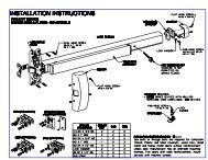
Now that you have prepared the opening, you’re ready to mount the operator<br />
unit itself. Follow these steps to mount the operator.<br />
PUSH,<br />
outswing<br />
mounting<br />
To mount the operator on an outswing door<br />
1. Determine the handing and side of the door. The D-<strong>4990</strong> mounts to right-hand<br />
reverse bevel (RHRB) and left-hand reverse bevel (LHRB) doors. The D-<strong>4990</strong>T<br />
(track) mounts to right hand (RH) and left hand (LH) doors. See Figure 1.8 on<br />
page 1-11.<br />
Note: The operator must be installed on the inside of the door.<br />
D-<strong>4990</strong>T<br />
D-<strong>4990</strong>T<br />
LH<br />
‘Inswing’ or RH<br />
‘Pull’ doors<br />
D-<strong>4990</strong> D-<strong>4990</strong><br />
<strong>Operator</strong><br />
Frame<br />
LHRB<br />
‘Outswing’ or<br />
‘Push’ doors<br />
RHRB<br />
Arms<br />
Door<br />
Figure 1.8<br />
Diagram showing how the D-<strong>4990</strong> and D-<strong>4990</strong>T mount to the four door swings<br />
2. Make sure to place the hinge side of the template to the hinge side of the door.<br />
See Figure 1.9.<br />
D-<strong>4990</strong> <strong>Low</strong> <strong>Energy</strong> <strong>Operator</strong> <strong>Installation</strong> <strong>Guide</strong> 1–11
Installing the D-<strong>4990</strong> low energy operator<br />
Template<br />
Hinge<br />
‘A’<br />
Note: Applies for<br />
all standard<br />
hinges. For special<br />
hinges (swing-clear,<br />
or other) and offset<br />
pivots, consult your<br />
authorized dealer.<br />
Push-side mount:<br />
‘A’ = 1¾ to 2”<br />
Figure 1.9<br />
Aligning the template to the door frame<br />
3. Make sure that the mounting surface is clean, flat and structural. Modify the<br />
door and frame as necessary.<br />
4. Make sure that a minimum clearance height of 6 3/4" (172 mm) from ceiling to<br />
door mounting surface is unobstructed. See Figure 1.10 on page 1-12.<br />
6 ¾”<br />
min<br />
vertical<br />
clearance<br />
ceiling/vertical obstruction<br />
6 5/8”<br />
max<br />
reveal<br />
Frame<br />
Aluminum<br />
& glass<br />
door<br />
Figure 1.10 Side cut-away view of an aluminum and glass door showing the maximum reveal.<br />
Also this view shows the minimum vertical head clearance.<br />
5. Tear along the perforated edges of the template.<br />
6. Peel off the adhesive strips from the back of this template and carefully place it<br />
in position on the frame by aligning the edges of template to the edges of the<br />
door frame. See Figure 1.9 on page 1-12.<br />
7. Peel off the adhesive strips from the back off the Arm Template and carefully<br />
place it in position on the door as shown in See Figure 1.11 on page 1-13..<br />
Follow the instructions on the arm template.<br />
1–12 D-<strong>4990</strong> <strong>Low</strong> <strong>Energy</strong> <strong>Operator</strong> <strong>Installation</strong> <strong>Guide</strong>
Installing the D-<strong>4990</strong> low energy operator<br />
Align arrows from<br />
base template to<br />
arm template.<br />
Base<br />
template<br />
Arm<br />
template<br />
Figure 1.11<br />
8. Mark for drilling a minimum of six mounting holes on the base. Make sure to<br />
use mounting holes at each end and in the middle of the base. There are a total<br />
of 22 mounting holes to choose from.<br />
9. Mark for drilling conduit if needed.<br />
Door<br />
10. Drill and tap the mounting holes. Use a #7, or 13/64" (0.201") drill and ¼"–20<br />
tap for the mounting screws. Remove the templates.<br />
11. Remove the cover screws and slide off the cover from the operator housing.<br />
See Figure 1.12.<br />
Cover<br />
<strong>Operator</strong><br />
housing<br />
Figure 1.12 Removing the cover from the housing<br />
12. Remove the motor/closer assembly.<br />
D-<strong>4990</strong> <strong>Low</strong> <strong>Energy</strong> <strong>Operator</strong> <strong>Installation</strong> <strong>Guide</strong> 1–13
Installing the D-<strong>4990</strong> low energy operator<br />
Motor/closer assy<br />
Motor/closer assy<br />
Figure 1.13 Removing the motor/closer assembly from the housing<br />
13. Mount back plate to the door frame using at least six 1/4-20 screws. See<br />
Figure 1.14 on page 1-14.<br />
Back plate<br />
Door<br />
frame<br />
Figure 1.14 Mounting the back plate to the frame<br />
Caution<br />
Caution: Do not drill through the door and do not drill using the back plate as<br />
a template: metal shavings or other debris could foul or short the electronics.<br />
14. Route power and control wiring to the back plate.<br />
1–14 D-<strong>4990</strong> <strong>Low</strong> <strong>Energy</strong> <strong>Operator</strong> <strong>Installation</strong> <strong>Guide</strong>
Installing the D-<strong>4990</strong> low energy operator<br />
15. Reinstall motor/closer assembly. Make sure that the harnesses are not trapped<br />
behind the motor/closer assembly. See Figure 1.13 on page 1-14.<br />
TASK 3:<br />
MOUNT THE PUSH PLATES OR OTHER ACTUATORS<br />
The type of actuator that you are installing will determine the installation<br />
procedures. See the manufacturer’s instructions that came with the product.<br />
Make sure to follow the ANSI/BHMA 156.19 requirements regarding the<br />
placement of actuators:<br />
ANSI/BHMA 156.19 requires that the actuator switch:<br />
■ “ . . . be activated by a knowing act.” See the glossary of terms for a complete<br />
definition, but in summary, the operator must be activated consciously. It<br />
must not open without the person’s initiating.<br />
■ be located within one to five feet from the door, but never more than 12 feet.<br />
■ must remain accessible from the swing side when the door is opened.<br />
■ not be located in a position where the user would be in the path of the<br />
moving door.<br />
■ be mounted so the user is in full sight of the door when activating the switch.<br />
■ have an installation height of a minimum of 34 in (864 mm) and a maximum of<br />
48 in (1219 mm).<br />
Types of actuators include:<br />
TASK 4:<br />
■<br />
■<br />
■<br />
■<br />
■<br />
■<br />
ATTACH ARMS<br />
push plates<br />
card readers<br />
key switches<br />
keypads<br />
proximity switches<br />
For information on how to wire the actuators to the D-<strong>4990</strong> <strong>Low</strong> <strong>Energy</strong><br />
<strong>Operator</strong>, See Typical application riser diagrams & wiring diagrams on<br />
page 1-4.<br />
There are two types of arms available for the D-<strong>4990</strong> or D-<strong>4990</strong>T <strong>Low</strong> <strong>Energy</strong><br />
<strong>Operator</strong>:<br />
■ Standard, push arms<br />
■ Track or parallel arms. These arms ship with the D-<strong>4990</strong>T series operator.<br />
Your application will determine the type of arms that you will install.<br />
D-<strong>4990</strong> <strong>Low</strong> <strong>Energy</strong> <strong>Operator</strong> <strong>Installation</strong> <strong>Guide</strong> 1–15
Installing the D-<strong>4990</strong> low energy operator<br />
Wall<br />
Inside or environmentally<br />
protected side<br />
Outside or environmentally<br />
unprotected<br />
side<br />
<strong>Operator</strong><br />
Arms<br />
Door<br />
Frame<br />
Swing out<br />
D-<strong>4990</strong> out-swing installation<br />
Wall<br />
<strong>Operator</strong><br />
Parallel<br />
or track Arms<br />
Door<br />
Swing in<br />
Frame<br />
D-<strong>4990</strong>T in-swing installation<br />
Figure 1.15 Comparing the two types of installations<br />
Standard or outswing arm installation<br />
1. If you’ve not done so already, use the arm template to locate the holes that<br />
will mount the arm to the door. Follow the instructions on the template.<br />
2. Drill and tap the mounting holes. Use a #17 or 11/64" (0.173") drill and 12-24<br />
tap for the mounting screws. Remove the template.<br />
3. Attach the main arm to the operator.<br />
4. Attach the bottom arm to the door.<br />
5. Connect the main arm to the bottom arm.<br />
1–16 D-<strong>4990</strong> <strong>Low</strong> <strong>Energy</strong> <strong>Operator</strong> <strong>Installation</strong> <strong>Guide</strong>
Track or in-swing arm installation<br />
Installing the D-<strong>4990</strong> low energy operator<br />
1. If you’ve not done so already, use the track arm template to locate the holes<br />
that will mount the arm to the door. Follow the instructions on the template.<br />
2. Drill the holes. If you’re using the screws provided:<br />
Qty 2 of #12/L pan-head tapping screw, or<br />
Qty 2 of #12-24 UNC/L pan-head machine screws – use #17 (0.173") drill<br />
size<br />
3. Attach the main arm to the operator.<br />
4. Attach the track to the door.<br />
5. Attach the roller to the arm and set into the track as shown in.<br />
TASK 5:<br />
MAKE ELECTRICAL CONNECTIONS<br />
Wiring<br />
overview<br />
The wiring connections that you need to make will depend on your application.<br />
For sample wiring diagrams, see See Typical application riser diagrams & wiring<br />
diagrams on page 1-4.<br />
For concealed wiring, route all wires through the back plate.<br />
Make connections in the following order:<br />
1. Input connections – actuators, keypads, etc.<br />
2. Output connections – electric strike, ELR exit devices, etc – if necessary<br />
3. AC power connections<br />
Use the following diagram and table to identify the wiring connections that you<br />
need.<br />
D-<strong>4990</strong> <strong>Low</strong> <strong>Energy</strong> <strong>Operator</strong> <strong>Installation</strong> <strong>Guide</strong> 1–17
Installing the D-<strong>4990</strong> low energy operator<br />
Activate 1<br />
Common 23456789<br />
Activate<br />
Common<br />
Door closed pos switch<br />
Common<br />
Vestibule IN entrapment<br />
Common<br />
Push and go<br />
Common 10<br />
TB1<br />
12 VDC+ spec 1<br />
Wireless receiver power 24 volts AC 23456789<br />
Wireless receiver power 24 volts AC<br />
Common<br />
Cycle counter<br />
Vestibule OUT entrapment<br />
NA<br />
Common +<br />
Common –<br />
Lock coil 10<br />
TB2<br />
TB3<br />
1 NA<br />
2 NA<br />
3 NA<br />
4 NA<br />
5 Hold<br />
6 Common<br />
7 Automatic<br />
8 Common<br />
9 NA<br />
10 NA<br />
Figure 1.16 Identifying the TB connectors<br />
Conn TB1 | Use to wire . . . TB2 | Use to wire . . . TB3 | Use to wire . . .<br />
Activation switch (push A 12 volt DC, 00 amp Not used.<br />
1 plate, keypad, etc) power supply.<br />
Common wire from the Wireless Receiver AC Not used.<br />
2 switch<br />
Power 24 VAC<br />
Activation switch Wireless Receiver AC Not used.<br />
3<br />
Power 24 VAC<br />
Common wire from the Common wire from the Not used.<br />
4<br />
switch<br />
Vestibule OUT Entrapment<br />
activation switch.<br />
5<br />
Door closed position<br />
switch from the D-<strong>4990</strong>. a<br />
Cycle counter.*<br />
Door hold open switch.*<br />
6<br />
7<br />
Common wire from the<br />
door closed position<br />
switch.*<br />
Activation switch<br />
located inside the vestibule<br />
and used to open<br />
the second door going<br />
inside.<br />
Activation switch<br />
located inside the vestibule<br />
and used to open<br />
the first door going out.<br />
Not used.<br />
Common wire from the<br />
door hold open switch.*<br />
Not used.<br />
1–18 D-<strong>4990</strong> <strong>Low</strong> <strong>Energy</strong> <strong>Operator</strong> <strong>Installation</strong> <strong>Guide</strong>
Installing the D-<strong>4990</strong> low energy operator<br />
Conn TB1 | Use to wire . . . TB2 | Use to wire . . . TB3 | Use to wire . . .<br />
8<br />
9<br />
10<br />
Common wire from the<br />
activation switch located<br />
inside the vestibule.<br />
‘Push and go’ door<br />
switch.*<br />
Common wire from the<br />
‘Push and go’ door<br />
switch.*<br />
Electric strike or lock<br />
power supply voltage.<br />
Also, positive wire from<br />
the lock.<br />
Common wire from the<br />
electric strike or lock<br />
power supply.<br />
Negative wire from the<br />
lock.<br />
Common wire from the<br />
automatic switch wire.<br />
For future use<br />
For future use.<br />
a<br />
This switch wiring comes from the factory already wired.<br />
Make input connections<br />
1. Locate the TB1 connector. See Figure 1.17.<br />
TB1<br />
TB2<br />
TB3<br />
Figure 1.17 Front view of the connector board<br />
2. Remove the connector header from its base if not already removed. This may<br />
make wiring easier.<br />
3. Splice the wires from the actuator to the actuator wiring that is already wired<br />
into TB1 connector.<br />
4. Plug the TB1 connector into the header on the circuit board.<br />
D-<strong>4990</strong> <strong>Low</strong> <strong>Energy</strong> <strong>Operator</strong> <strong>Installation</strong> <strong>Guide</strong> 1–19
Installing the D-<strong>4990</strong> low energy operator<br />
Make output connections<br />
If you are using an electric strike, ELR exit device, or other electric locking device,<br />
follow these steps. If not, you can skip to Make power connections on page 1–20.<br />
1. Locate the TB2 connector. See Figure 1.17.<br />
2. Remove the connector plug from its socket. This may make wiring easier.<br />
3. Strip and connect the wires from the lock into TB2 connector.<br />
4. Plug the TB2 connector back into the header on the circuit board.<br />
Make power connections<br />
Make sure that all power is off before making connections.<br />
1. Locate the TB1 connector. See Figure 1.17.<br />
2. Remove the connector plug from its header if it’s not already removed. This<br />
may make wiring easier.<br />
3. Strip and splice the wires from the power source. Mate all white wires from J6<br />
and switches together. Mate the black (hot) wires together. Terminate the<br />
ground screw.<br />
4. Mate the motor connector plug to motor socket 1. See Figure 1.18.<br />
J6 Power<br />
connector<br />
Motor 1<br />
socket<br />
Figure 1.18 Front view of the back plate showing motor connector 1<br />
1–20 D-<strong>4990</strong> <strong>Low</strong> <strong>Energy</strong> <strong>Operator</strong> <strong>Installation</strong> <strong>Guide</strong>
TASK 6:<br />
MAKE INITIAL SETTINGS AND ADJUSTMENTS<br />
Installing the D-<strong>4990</strong> low energy operator<br />
In most cases, the D-<strong>4990</strong> <strong>Low</strong> <strong>Energy</strong> <strong>Operator</strong> comes factory pre-set to suit most<br />
application requirements. But expect to make some minor adjustments.<br />
Checklist<br />
before turning<br />
on power<br />
Use the following checklist before making adjustment:<br />
❏ All hardware installed<br />
❏ All electrical wiring connections made and properly terminated; make sure no<br />
wiring is exposed.<br />
❏ Cover removed<br />
❏ Door closed and unlocked<br />
❏ Door path clear<br />
Do not turn on power until all wires are properly terminated and the unit is firmly<br />
affixed to the door and frame.<br />
Turn on power<br />
1. Turn the unit on by pushing the lighted switch to the ON position. See<br />
Figure 1.19.<br />
POWER<br />
MODE<br />
ON OFF<br />
HOLD<br />
OPEN<br />
DAY<br />
NIGHT<br />
POWER<br />
ON OFF<br />
HOLD<br />
OPEN<br />
MODE<br />
DAY<br />
NIGHT<br />
Figure 1.19 Power and mode switches shown set to normal operation<br />
2. Move the mode switch to DAY.<br />
As soon as power is applied, the unit will go through a first-time, self-test cycle.<br />
After a 30-second delay the unit will report any errors it finds via the digital<br />
readout. See page 1–26.<br />
You can also use the test button in place of an actuating device to force the<br />
operator through its normal cycle. See page 1–25.<br />
D-<strong>4990</strong> <strong>Low</strong> <strong>Energy</strong> <strong>Operator</strong> <strong>Installation</strong> <strong>Guide</strong> 1–21
Installing the D-<strong>4990</strong> low energy operator<br />
Door cycle<br />
stages<br />
The door goes through five stages in one complete cycle, depending on the<br />
application. See Figure 1.20. They are:<br />
A Opening from closed to back-check<br />
B<br />
C<br />
D<br />
E<br />
Back-check to full open<br />
Full open hold time<br />
Hold time to latch-check or 10 degrees<br />
Latch-check or 10 degrees to close<br />
D-<strong>4990</strong><br />
E<br />
A<br />
0°<br />
10°<br />
A Opening from closed to<br />
back-check<br />
B Back-check to full open<br />
C Full open hold time<br />
D Hold time to latch-check<br />
E Latch-check to close<br />
60°<br />
B<br />
70°<br />
80° 90°<br />
D<br />
C<br />
Figure 1.20 View showing the stages of the cycles<br />
To determine the minimum (fastest) opening times, follow these steps<br />
1. Determine the width and weight of your door. If you cannot weigh the door,<br />
use the following table to find its approximate weight:<br />
Type of door<br />
• Solid core wood<br />
• 20 ga flush hollow metal<br />
• Aluminum × 1/4" glass<br />
• Mineral core wood<br />
• 16 ga flush hollow metal<br />
• Aluminum × 1" glass<br />
Weight per sq. ft.<br />
5.5 lbs 115 lbs<br />
7.0 lbs 147 lbs<br />
Typical 3’ × 7’<br />
door weight<br />
1–22 D-<strong>4990</strong> <strong>Low</strong> <strong>Energy</strong> <strong>Operator</strong> <strong>Installation</strong> <strong>Guide</strong>
Installing the D-<strong>4990</strong> low energy operator<br />
For example, you have a solid core wood door, 3 feet wide by 8 feet tall:<br />
3 feet × 8 feet = 24 ft 2 >> 24 ft 2 × 5.5 lbs/ft 2 = 132 lbs<br />
2. Determine the minimum (fastest) opening time 0 to 80 degrees using the<br />
number that you computed above and Table 1. The minimum opening time<br />
for any door is 3 seconds.<br />
So for the example above of a door estimated to weigh 132 lbs with a 36<br />
inch width, you would use the 150 lb maximum requirement of 3.5<br />
seconds as the minimum amount of time (fastest) that the door could open<br />
or close.<br />
Table 1<br />
Minimum opening time to back check or 80 degrees (whichever occurs first)<br />
and<br />
Minimum closing time from 90 degrees to latch check or 10 degrees<br />
(whichever occurs first)<br />
Max door weight Door width in inches<br />
in pounds (lbs) 30 in 36 in 42 in 48 in<br />
100 lbs 3.0 sec 3.0 sec 3.5 sec 4.0 sec<br />
125 lbs 3.0 sec 3.5 sec 4.0 sec 4.5 sec<br />
150 lbs 3.0 sec 3.5 sec 4.0 sec 4.5 sec<br />
175 lbs 3.0 sec 4.0 sec 4.5 sec 5.0 sec<br />
200 lbs 3.5 sec 4.0 sec 4.5 sec 5.5 sec<br />
3. Determine the minimum closing time, from 90 to 10 degrees or latch check,<br />
using the number that you computed above and Table 1. The minimum<br />
closing time for any door is 3 seconds.<br />
The minimum closing time from 10 degrees to fully closed for any door is<br />
1.5 seconds.<br />
4. Use the potentiometers, digital readout and spring adjustment to adjust the<br />
opening and closing times to be compliant to ANSI/BHMA 156.19.<br />
D-<strong>4990</strong> <strong>Low</strong> <strong>Energy</strong> <strong>Operator</strong> <strong>Installation</strong> <strong>Guide</strong> 1–23
Installing the D-<strong>4990</strong> low energy operator<br />
The complete cycle time for a 132 pound door:<br />
Door<br />
cycle<br />
stage Cycle Minimum time<br />
A Opening time to 80 degrees 3.5 seconds<br />
B 80 degrees to full opening of 90 degrees 1 second<br />
C Hold open time delay 5 seconds<br />
D Closing time to 10 degrees 3.5 seconds<br />
E 10 degrees to close 1.5 seconds<br />
Total minimum cycle time<br />
14.5 seconds<br />
Check force<br />
and Kinetic<br />
energy<br />
Make sure that the door can stop and open with the minimum amount of force<br />
specified in ANSI/BHMA 156.19. To measure this, use a force gauge by putting it<br />
one inch from the latch edge.<br />
1. Check that the door can stop using 15 lbf (foot-pounds) or less.<br />
2. Check that the door can open (release the latch, that is, if there is a latch) with<br />
15 lbf or less.<br />
3. Check that the door can start opening (set the door in motion) with 30 lbf or<br />
less.<br />
4. Check that the door can fully open with 15 lbf or less.<br />
Potentiometers<br />
Use the potentiometers on the electronics board to fine-tune the door operator.<br />
Each potentiometer or ‘POT’ allows you to isolate and adjust each movement of<br />
the door operator.<br />
1–24 D-<strong>4990</strong> <strong>Low</strong> <strong>Energy</strong> <strong>Operator</strong> <strong>Installation</strong> <strong>Guide</strong>
Installing the D-<strong>4990</strong> low energy operator<br />
7<br />
5<br />
3<br />
1<br />
9<br />
8<br />
6<br />
4<br />
2<br />
Use the adjustment<br />
screwdriver to make POT<br />
adjustments. The POTs are<br />
factory-set mid-way. Turn the<br />
POTS clockwise to increase<br />
time, speed, torque, etc.<br />
Potentiometers<br />
Note: POT 9 is<br />
arranged out of order<br />
Test switch<br />
Figure 1.21 View of the electronics board showing the nine potentiometers<br />
Use the following table to make adjustments to door operation:<br />
POT<br />
number Used to adjust Use this when . . .<br />
1 Hold-open time the time that the door holds open is too<br />
short or too long.<br />
Note: Hold open time can be up to 30 seconds.<br />
The hold open time must be a minimum<br />
of 5 seconds after the door is fully<br />
open.<br />
2 Full open position the door either does not open far enough<br />
or opens too wide.<br />
3 NA (not used)<br />
4 Stall force and only when hold open motor is drifting<br />
closed.<br />
5 Open check speed you need to set the door speed during the<br />
back check period. Make sure that the<br />
speed is compliant.<br />
6 Open sweep speed the speed that the door sweeps open is too<br />
fast or too slow.<br />
7 Opening torque the force of the opening is too strong or<br />
too weak. The door should stop when<br />
obstructed. It should not be difficult to<br />
stop the door by hand.<br />
D-<strong>4990</strong> <strong>Low</strong> <strong>Energy</strong> <strong>Operator</strong> <strong>Installation</strong> <strong>Guide</strong> 1–25
Installing the D-<strong>4990</strong> low energy operator<br />
POT<br />
number Used to adjust Use this when . . .<br />
8 NA (not used)<br />
9 Sequencer the vestibule second door delay needs to<br />
be adjusted.<br />
Digital readout<br />
The digital readout is a diagnostic and adjustment tool that allows you to monitor<br />
the operator as it moves from one state to the next. Use this tool as you make<br />
adjustments.<br />
Number <strong>Operator</strong> state<br />
01 Initialization<br />
02 Door closed<br />
03 Electric strike enabled (DIP switch 2;<br />
see the DIP switch table above)<br />
04 Door moving open<br />
05 Door moving through back-check<br />
06 Full open or hold open<br />
07 Door moving closed<br />
08 Door obstructed (moving open only)<br />
DIP switch<br />
settings<br />
Six DIP switches define a feature’s mode or enable or disable a feature. For<br />
example, your application may include locking and unlocking the door by an<br />
electric strike. In that case, you will need to enable the normally (factory-preset)<br />
disabled switch by flipping DIP switch 2 to ON. See Figure 1.22 to locate and help<br />
identify the DIP switches.<br />
1–26 D-<strong>4990</strong> <strong>Low</strong> <strong>Energy</strong> <strong>Operator</strong> <strong>Installation</strong> <strong>Guide</strong>
Installing the D-<strong>4990</strong> low energy operator<br />
Digital<br />
readout. See<br />
page 1–26.<br />
Note that all<br />
switches are<br />
set to OFF<br />
(down)<br />
DIP switches<br />
Figure 1.22 View of the electronic board showing the DIP switches and digital readout<br />
The following table identifies the individual DIP switches and their factory default<br />
settings. All DIP switches are factory set to OFF. For a definition of terms, see the<br />
Glossary.<br />
DIP<br />
switch<br />
number DIP switch name ON OFF<br />
1 Electric strike logic Fail-secure Fail-safe<br />
2 Electric strike on/off Enabled Disabled<br />
3 Out-swing/in-swing In-swing Out-swing<br />
logic<br />
4 ‘Push and Go’ a Enabled Disabled<br />
5 Power close Enabled Disabled<br />
6 Back-check length NA NA<br />
7 Future use NA NA<br />
8 Factory use only NA NA<br />
a<br />
Push and Go, if enabled, will activate when door are<br />
pushed open past 10 degrees. This is activated by<br />
switch not motor voltage.<br />
D-<strong>4990</strong> <strong>Low</strong> <strong>Energy</strong> <strong>Operator</strong> <strong>Installation</strong> <strong>Guide</strong> 1–27
Installing the D-<strong>4990</strong> low energy operator<br />
So if you . . .<br />
TASK 7:<br />
■<br />
■<br />
■<br />
■<br />
■<br />
Have an electric strike or any kind of locking device, set DIP switch 2 to ON.<br />
Have an electric strike or any kind of locking device, set DIP switch 1 to ON<br />
for fail-secure (when power fails, the lock will be secure or locked) or leave it<br />
OFF for fail-safe (when power fails, the lock will be safe or unlocked).<br />
Have an in-swing or pull door (has a parallel arm), set DIP switch 3 to ON.<br />
Want to use the Push and Go feature that allows someone to simply push on<br />
the door to start the operator, set DIP switch 4 to ON.<br />
Want to use the Power close feature that forces the door closed in windy<br />
conditions or where stack pressures build inside a building, set DIP switch 5<br />
to ON.<br />
COMPLETE THE INSTALLATION<br />
Before putting the door into operation, three more steps are required to complete<br />
the installation:<br />
■<br />
■<br />
■<br />
Applying door decals<br />
Testing the door against the ANSI/BHMA 156.19 standard<br />
Reinstall the cover<br />
Applying<br />
decals<br />
For complete instructions on the placement of door decals, see the instructions<br />
packaged with the decals.<br />
ANSI/BHMA requires that:<br />
“doors shall be equipped with signage visible from either side of the door,<br />
instructing the user as to the operation and function of the door. The signs<br />
shall be mounted 50" ± 12" (1270 mm ± 305 mm) from the floor to the<br />
center line of the sign. The letters shall be 5/8 inch (16 mm) high<br />
minimum.”<br />
and<br />
“All low energy doors shall be marked with signage visible from both sides<br />
of the door, with the words ‘AUTOMATIC CAUTION DOOR’. . . .When a<br />
Knowing Act Switch is used to initiate the operation of the door operator,<br />
the doors shall be provided with signs on each side of the door where the<br />
switch is located, with the message ‘ACTIVATE SWITCH TO OPERATE’.”<br />
and<br />
“When push/pull is used to initiate the operation of the door operator, the<br />
doors shall be provided with the message ‘PUSH TO OPERATE’ on the<br />
push side of the door and ‘PULL TO OPERATE’ on the pull side of the<br />
door.”<br />
1–28 D-<strong>4990</strong> <strong>Low</strong> <strong>Energy</strong> <strong>Operator</strong> <strong>Installation</strong> <strong>Guide</strong>
Installing the D-<strong>4990</strong> low energy operator<br />
SAFETY CHECKS<br />
The following safety checks must be made daily to assure proper door operation:<br />
■ For safe operation, refer to the Daily Safety Check Sheet for safety procedures.<br />
If you need a copy, call your local PHI distributor.<br />
■ Test the doors daily and after any power outage. Verify operation of any<br />
sensors.<br />
■ Check the condition of the door, hinges, and safety decals.<br />
■ If there are any problems, DISCONTINUE DOOR OPERATION IMMEDIATELY!<br />
Notify your local authorized PHI distributor for repair.<br />
D-<strong>4990</strong> <strong>Low</strong> <strong>Energy</strong> <strong>Operator</strong> <strong>Installation</strong> <strong>Guide</strong> 1–29
Installing the D-<strong>4990</strong> low energy operator<br />
1–30 D-<strong>4990</strong> <strong>Low</strong> <strong>Energy</strong> <strong>Operator</strong> <strong>Installation</strong> <strong>Guide</strong>
2 IMPORTANT<br />
TERMS<br />
The following are important terms that will help you better understand the<br />
D-<strong>4990</strong> <strong>Low</strong> <strong>Energy</strong> <strong>Operator</strong>.<br />
AAADM<br />
back-check<br />
day mode<br />
electric strike<br />
encoder<br />
Abbreviation for the organization, American Association of<br />
Automatic Door Manufacturers. This organization has an inspector<br />
certification program that trains and certifies automatic door operator<br />
inspectors and technicians.<br />
A safety function that prevents or checks the door when a gust of wind<br />
or some other force tries to force the door to open too quickly,<br />
potentially damaging property or injuring people.<br />
Normal operational mode when all features are fully functional. See<br />
also night mode.<br />
A locking device mounted in the door frame that electrically holds and<br />
releases a latch. ‘Electric strike’ the term can also be used generally for<br />
any kind of electrical locking device.<br />
Combination of a magnet rotating on the shaft at the end of the motor,<br />
and Hall effect transistors that send pulses to the control every time<br />
the motor turns. When the door is powered up it will open slowly and<br />
allow the encoder and processor to count the pulses from fully closed<br />
to fully open. These pulses are used to indicate when a door should go<br />
into back-check or when it’s at its open limit.<br />
D-<strong>4990</strong> <strong>Low</strong> <strong>Energy</strong> <strong>Operator</strong> <strong>Installation</strong> & User <strong>Guide</strong> 2–1
Important Terms<br />
fail-safe<br />
fail-secure<br />
hold-open time<br />
knowing act<br />
mode switch<br />
night mode<br />
power close<br />
‘POT’<br />
potentiometer<br />
reveal<br />
sequential<br />
operation<br />
stack pressure<br />
vestibule<br />
An automatic switching feature of an electrified lock that ensures that<br />
the security device unlocks when power fails and until power is<br />
restored. See also fail-secure.<br />
An automatic switching feature of an electrified lock that ensures that<br />
the security device locks when power fails and until power is restored.<br />
See also fail-safe.<br />
The time in seconds that the door remains open at 90 degrees. The<br />
minimum hold-open time is 5 seconds, the maximum is 30 seconds.<br />
According to ANSI/BHMA 156.19: “Consciously initiating the powered<br />
opening of a low-energy door using acceptable methods including:<br />
wall or jamb-mounted contact switches such as push plates; fixed noncontact<br />
switches; the action of manual opening (pushing and pulling)<br />
a door; and controlled access devices such as keypads card readers,<br />
and keyswitches.”<br />
Controls Hold Open and operating mode (Day or Night). See Day<br />
mode and Night mode.<br />
Mode in which all actuators are not operational, except the push to<br />
open feature remains active.<br />
The optional feature designed to ensure that the door completely<br />
latches closed, normally used in conditions where wind or stack<br />
pressures could prevent the door from closing.<br />
See potentiometer.<br />
A variable, adjustable resistor used to vary the amount of current that<br />
flows to a device.<br />
The distance from the mounting surface of the operator to the face of<br />
the door.<br />
An automatic feature that provides for sequential operation of two<br />
units. For example, in a vestibule the opening of the second unit can<br />
be delayed 1 to 30 seconds after the opening of the first.<br />
A force on the door, created by an internal air handling system or<br />
external environmental conditions.<br />
See sequential operation.<br />
2–2 D-<strong>4990</strong> <strong>Low</strong> <strong>Energy</strong> <strong>Operator</strong> <strong>Installation</strong> & User <strong>Guide</strong>
Notes: