8431 EN - MTS Messtechnik Schaffhausen GmbH
8431 EN - MTS Messtechnik Schaffhausen GmbH
8431 EN - MTS Messtechnik Schaffhausen GmbH

Create successful ePaper yourself
Turn your PDF publications into a flip-book with our unique Google optimized e-Paper software.
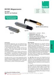
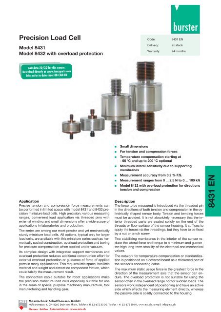
Precision Load Cell<br />
Model <strong>8431</strong><br />
Model 8432 with overload protection<br />
Code:<br />
Delivery:<br />
Warranty:<br />
<strong>8431</strong> <strong>EN</strong><br />
ex stock<br />
24 months<br />
<br />
<br />
<br />
Application<br />
Precise tension and compression force measurements can<br />
be performed in limited space with model <strong>8431</strong> and 8432 precision<br />
miniature load cells. High precision, various measuring<br />
ranges, convenient load application via threaded pins with<br />
external winding and small dimensions offer a wide scope of<br />
applications in laboratories and production.<br />
The series are among our most precise and yet mechanically<br />
sturdy miniature load cells. All options, typical only for larger<br />
load cells, are available with this miniature series such as hermetically<br />
sealed construction, overload protection and boring<br />
for pressure compensation when applied under vacuum.<br />
Its complex design with integrated support membranes and<br />
overload protection reduces additional construction effort for<br />
external overload protection or guidance of force of applied<br />
parts in many applications. This requires little space, has little<br />
material and weight and almost no component friction, which<br />
could falsify the measurement result.<br />
The connection cable suitable for robot applications make<br />
the precision miniature load cells especially suitable for use<br />
in the areas of special purpose machinery manufacture, tool<br />
manufacturing and handling gear.<br />
<br />
<br />
<br />
<br />
<br />
<br />
<br />
Small dimensions<br />
For tension and compression forces<br />
Temperature compensation starting at<br />
- 55 °C and up to 200 °C optional<br />
Minimum lateral sensitivity due to supporting<br />
membranes<br />
Measurement accuracy from 0.2 % F.S.<br />
Measurement ranges from 0 ... 2.5 N to 0 ... 100 kN<br />
Model 8432 with overload protection for directions<br />
tension and compression<br />
Description<br />
The force to be measured is introduced via the threaded pin<br />
in the directions of both tension and compression in the cylindrically<br />
shaped sensor body. Torsion and bending forces<br />
must be avoided. It is not absolutely necessary that the interior<br />
threaded parts are seated solidly on the end of the<br />
threads or floor surface of the sensor housing. It suffices to<br />
apply the forces via the threadings, but they have to be fixed<br />
by a nut or pinch screw.<br />
Two stabilizing membranes in the interior of the sensor reduce<br />
the lateral force and torque to a minimum and guarantee<br />
high long-term stability of the electrical and mechanical<br />
values.<br />
The network for temperature compensation or standardization<br />
is positioned on a covered board as a thickened part of<br />
the sensor‘s connecting cable.<br />
The maximum static usage force is the greatest force in the<br />
direction of the measurement axis that the sensor can endure.<br />
The overload protection is not suitable for using the<br />
sensor often in the overload range nor for sudden loads. The<br />
sensors work independent of positioning and have an active<br />
side which effects the measuring element directly, whereas<br />
the passive side is solidly connected to the housing.<br />
<strong>8431</strong> <strong>EN</strong><br />
<strong>MTS</strong><br />
<strong>Messtechnik</strong> <strong>Schaffhausen</strong> <strong>GmbH</strong><br />
Mühlenstrasse 4, CH-8260 Stein am Rhein, Telefon +41 52-672 50 00, Telefax +41 52-672 50 01, www.mts.ch, e-mail: info@mts.ch<br />
Messen Prüfen Automatisieren www.mts.ch
<strong>8431</strong> <strong>EN</strong> -2<br />
Technical Data<br />
Model <strong>8431</strong><br />
Order Code<br />
Measurement<br />
Range<br />
Dimensions [mm]<br />
A ø B C ø D F G H L<br />
<strong>8431</strong>-5005 0 ... 5 N 17.4 4.8 6.4 25.4 2.8 0.8 12.7 9.6<br />
<strong>8431</strong>-5010 0 ... 10 N 17.4 4.8 6.4 19.4 1.3 0.4 12.7 5.9<br />
<strong>8431</strong>-5020 0 ... 20 N 17.4 4.8 6.4 19.1 1.3 0.4 12.7 5.9<br />
<strong>8431</strong>-5050 0 ... 50 N 17.4 4.8 6.4 19.1 1.3 0.4 12.7 5.9<br />
<strong>8431</strong>-5100 0 ... 100 N 25.4 6.4 6.4 25.4 2.8 0.2 15.5 6.6<br />
<strong>8431</strong>-5200 0 ... 200 N 25.4 6.4 6.4 25.4 2.8 0.2 15.5 6.6<br />
<strong>8431</strong>-5500 0 ... 500 N 25.4 6.4 6.4 25.4 2.8 0.2 15.5 6.6<br />
<strong>8431</strong>-6001 0 ... 1 kN 25.4 6.4 9.7 25.4 0.8 0.5 14.0 7.0<br />
<strong>8431</strong>-6002 0 ... 2 kN 25.4 6.4 9.7 25.4 0.8 0.5 14.0 7.0<br />
<strong>8431</strong>-6005 0 ... 5 kN 25.4 6.4 9.7 25.4 0.8 0.5 14.0 7.0<br />
<strong>8431</strong>-6010 0 ... 10 kN 25.4 9.5 12.7 25.4 0.8 - 19.1 6.5<br />
<strong>8431</strong>-6020 0 ... 20 kN 28.6 9.5 16.0 31.8 0.3 - 25.4 14.2<br />
<strong>8431</strong>-6040 0 ... 40 kN 30.3 9.5 22.4 35.0 0.5 - 28.7 15.0<br />
<strong>8431</strong>-6050 0 ... 50 kN 30.3 9.5 22.4 35.0 0.5 - 28.7 15.0<br />
<strong>8431</strong>-6100 0 ... 100 kN 42.7 9.5 42.0 60.0 0.5 - 48.0 23.6<br />
Model 8432 with bidirectional overload protection<br />
Order Code<br />
Measurement<br />
Range<br />
Dimensions [mm]<br />
A ø B C ø D F G H L<br />
8432-5002 0 ... 2.5 N 25.4 9.7 6.4 25.4 2.8 0.8 21.9 9.6<br />
8432-5005 0 ... 5 N 25.4 9.7 6.4 25.4 2.8 0.8 21.9 9.6<br />
8432-5010 0 ... 10 N 25.4 9.7 6.4 25.4 2.8 0.8 21.9 9.6<br />
8432-5020 0 ... 20 N 25.4 9.7 6.4 25.4 2.8 0.8 21.9 9.6<br />
8432-5050 0 ... 50 N 25.4 9.7 6.4 25.4 2.8 0.8 21.9 9.6<br />
8432-5100 0 ... 100 N 25.4 6.3 6.4 25.4 2.8 0.8 21.9 9.6<br />
8432-5200 0 ... 200 N 25.4 6.3 6.4 25.4 2.8 0.8 21.9 9.6<br />
8432-5500 0 ... 500 N 25.4 6.3 6.4 25.4 2.8 0.8 21.9 9.6<br />
8432-6001 0 ... 1 kN 29.4 9.5 8.0 31.8 2.6 - 23.9 10.8<br />
8432-6002 0 ... 2 kN 32.2 9.5 9.6 38.1 0.7 - 26.7 14.5<br />
Electrical values<br />
Dimensional drawing models <strong>8431</strong> and 8432<br />
Bridge resistance: (full bridge):<br />
measuring range ≤ 0 ... 5 N semi conductor strain gauge<br />
500 Ω, nominal<br />
measuring range ≥ 0 ... 10 N foil strain gauge 350 Ω, nominal<br />
"Active" side<br />
Reference excitation voltage:<br />
measuring range ≤ 0 ... 50 N<br />
5 V DC or AC<br />
measuring range ≥ 0 ... 100 N<br />
10 V DC or AC<br />
Nominal sensitivity:<br />
measuring range ≤ 0 ... 5 N 15 mV/V ... 40 mV/V, nominal<br />
measuring range 0 ... 10 N 1.5 mV/V, nominal<br />
measuring range ≥ 0 ... 20 N<br />
2 mV/V, nominal<br />
Insulation resistance:<br />
5000 MΩ at 50 V DC<br />
Calibration resistor: 59 kΩ ± 0.1 %<br />
The bridge output voltage caused by a shunt of this value is given<br />
in the calibration protocol.<br />
Environmental conditions<br />
Range of operating temperature: - 55 °C ... + 120 °C<br />
The CAD drawing (3D/2D) for this sensor can be imported online<br />
directly into your CAD system.<br />
Download via www.burster.com or directly at www.traceparts.com.<br />
For further information about the burster traceparts cooperation refer<br />
to data sheet 80-CAD-<strong>EN</strong>.<br />
Nominal temperature range: + 15 °C ... + 70 °C<br />
Influence of temperature on zero:<br />
measuring range ≤ 0 ... 5 N ≤ ± 0.05 % F.S./K<br />
measuring range ≥ 0 ...10 N ≤ ± 0.03 % F.S./K<br />
Influence of temperature on sensitivity:<br />
measuring range ≤ 0 ... 5 N ≤ ± 0.05 % F.S./K<br />
measuring range ≥ 0 ...10 N ≤ ± 0.03 % F.S./K<br />
Mechanical Value<br />
Measurement error, consisting of relative non-linearity and<br />
relative hysteresis:<br />
measuring range ≤ 0 ...1 kN < ± 0.15 % F.S.<br />
measuring range ≥ 0 ...2 kN < ± 0.2 % F.S.<br />
relative variation on unchanged mounting position:<br />
measuring range ≤ 0 ...10 N < ± 0.1 % F.S.<br />
measuring range ≥ 0 ...20 N < ± 0.05 % F.S.<br />
Kind of measurement:<br />
Tensile and compressive forces<br />
calibration in tensile direction (preferential direction) Dimensions:<br />
expect a changed characteristic, if using the sensor against the Weight:<br />
preferential direction.<br />
<strong>MTS</strong> <strong>Messtechnik</strong> <strong>Schaffhausen</strong> <strong>GmbH</strong><br />
Mühlenstrasse 4, CH-8260 Stein am Rhein, Telefon +41 52-672 50 00, Telefax +41 52-672 50 01, www.mts.ch, e-mail: info@mts.ch<br />
Messen Prüfen Automatisieren www.mts.ch<br />
Maximum static force in operation:<br />
model <strong>8431</strong><br />
all measuring range<br />
bidirectional 150 % of nominal load<br />
model 8432<br />
all measuring range<br />
bidirectional 100 % of nominal load<br />
Maximum static load to overload stop:<br />
model 8432<br />
measuring range ≤ 0 ... 500 N bidirectional 500 % of nominal load<br />
measuring range 0 ... 1000 N bidirectional 250 % of nominal load<br />
measuring range 0 ... 2000 N bidirectional 200 % of nominal load<br />
refer to table and dimensional drawing<br />
see table<br />
752-00<strong>8431</strong><strong>EN</strong>-5099-121522
Technical Data Model <strong>8431</strong><br />
<strong>8431</strong> <strong>EN</strong> - 3<br />
Order Code Measurement Range Thread Resonance<br />
Weight [g] Thread Adapter*<br />
Frequency<br />
T [kHz] with / without Cable Model<br />
<strong>8431</strong>-5005 0 ... 5 N M 4 x 0.7 0.3 25 / 18 <strong>8431</strong>-ZX01<br />
<strong>8431</strong>-5010 0 ... 10 N M 4 x 0.7 0.3 25 / 18 <strong>8431</strong>-ZX01<br />
<strong>8431</strong>-5020 0 ... 20 N M 4 x 0.7 0.7 25 / 18 <strong>8431</strong>-ZX01<br />
<strong>8431</strong>-5050 0 ... 50 N M 4 x 0.7 0.9 25 / 18 <strong>8431</strong>-ZX01<br />
<strong>8431</strong>-5100 0 ... 100 N M 5 x 0.8 1.2 65 / 34 <strong>8431</strong>-ZX02<br />
<strong>8431</strong>-5200 0 ... 200 N M 5 x 0.8 2.7 65 / 34 <strong>8431</strong>-ZX02<br />
<strong>8431</strong>-5500 0 ... 500 N M 5 x 0.8 3.3 65 / 34 <strong>8431</strong>-ZX02<br />
<strong>8431</strong>-6001 0 ... 1000 N M 6 x 1.0 5.3 68 / 40 -<br />
<strong>8431</strong>-6002 0 ... 2000 N M 6 x 1.0 7.5 68 / 40 -<br />
<strong>8431</strong>-6005 0 ... 5000 N M 6 x 1.0 9.7 68 / 40 -<br />
<strong>8431</strong>-6010 0 ... 10 kN M10 x 1.5 1.3 88 / 60 -<br />
<strong>8431</strong>-6020 0 ... 20 kN M12 x 1.5 1.0 144 / 124 -<br />
<strong>8431</strong>-6040 0 ... 40 kN M20 x 1.5 1.0 264 / 238 -<br />
<strong>8431</strong>-6050 0 ... 50 kN M20 x 1.5 1.0 264 / 238 -<br />
<strong>8431</strong>-6100 0 ... 100 kN M30 x 2.0 0.5 1150 / 1124 -<br />
Model 8432 with bidirectional overload protection<br />
Order Code Measurement Range Thread Resonance<br />
Weight [g] Thread Adapter*<br />
Frequency<br />
T [kHz] with / without Cable Model<br />
8432-5002 0 ... 2.5 N M4 x 0.7 0,2 92 / 68 8432-ZX01<br />
8432-5005 0 ... 5 N M4 x 0.7 0.2 92 / 68 8432-ZX01<br />
8432-5010 0 ... 10 N M4 x 0.7 0.2 92 / 68 8432-ZX01<br />
8432-5020 0 ... 20 N M4 x 0.7 0.35 92 / 68 8432-ZX01<br />
8432-5050 0 ... 50 N M4 x 0.7 0.6 92 / 68 8432-ZX01<br />
8432-5100 0 ... 100 N M5 x 0.8 1.2 92 / 68 8432-ZX02<br />
8432-5200 0 ... 200 N M5 x 0.8 2.7 92 / 68 8432-ZX02<br />
8432-5500 0 ... 500 N M5 x 0.8 3.3 92 / 68 8432-ZX02<br />
8432-6001 0 ... 1000 N M6 x 1.0 3.4 142 / 125 8432-ZX03<br />
8432-6002 0 ... 2000 N M6 x 1.0 3.8 238 / 210 8432-ZX04<br />
* By ordering studs as spare parts, state serial number of the load cell.<br />
Dynamic load:<br />
recommended<br />
70 % of nominal load<br />
possible<br />
100 % of nominal load<br />
Deflection:<br />
15 μm ... 50 μm<br />
Material: stainless steel 17-4 PH (similar to 1.4542)<br />
Electrical connection:<br />
Shielded, high flexible, Teflon isolated cable, length approx. 1.5 m,<br />
diameter 2.5 mm. The cable has a 50 mm bend protection at the<br />
sensor body, outer diameter 3.6 mm. The minimum bending radius<br />
of the cable is 30 mm, or 8 mm at static operations. At the end of<br />
the cable is, behind the cable's isolation, a small balancing resistor.<br />
Do not remove this resistor.<br />
Only model <strong>8431</strong>, measuring range ≥ 0 ... 50 kN<br />
High flexible, Teflon isolated strands, length approx. 1.5 m, overall<br />
diameter 1,2 mm; minimum bending radius of the cable 20 mm,<br />
or 5 mm for static operations. Balancing resistors on a heat shrink<br />
tube covered circuit board at the middle of the cable. Length of<br />
the circuit board 70 mm, width 7 mm. The strands are shielded<br />
between sensor housing and circuit board. There is no bend<br />
protection available.<br />
Protection class: acc. to <strong>EN</strong> 60529 IP65<br />
Wiring code:<br />
red excitation voltage positive<br />
black excitation voltage negative<br />
green output signal negative<br />
white output signal positive<br />
Dimensions:<br />
refer to table and dimensional drawing<br />
Wiring for submarine cable:<br />
red excitation voltage positive<br />
brown excitation voltage negative<br />
yellow output signal negative<br />
orange output signal positive<br />
Order Information<br />
Precision miniature load cell, measurement range 0 ... 2000 N<br />
state options additionally <strong>8431</strong>-6002<br />
Options<br />
Extension of the nominal temperature range<br />
to -30 °C ... 95 °C<br />
...-VxExxxxx<br />
Extension of the nominal temperature range<br />
to 20 °C ... 120 °C<br />
...-VxFxxxx<br />
Extension of the nominal temperature range<br />
to 20 °C ... 160 °C<br />
...-VxGxxxxx<br />
Extension of the nominal temperature range<br />
to 20 °C ... 200 °C, measuring ranges ≥ 0 ... 100 N ...-VxHxxxxx<br />
Extension of the nominal temperature range<br />
to -55 °C ... 120 °C<br />
...-VxIxxxxx<br />
Submarine cable, up to 80 °C, pressure proof up to 35 bar,<br />
length of cable 3 m, diameter of cable 6.5 mm. Please inform us,<br />
if you wish another cable length.<br />
Although the dimensions A and ∅ B - see drawing -<br />
are changing to A = 90 mm, ∅ B = 12.7 mm. ...-VxxxIxxx<br />
Note: All options, stated above, are only available for load cells<br />
of measurement ranges ≤ 0 ... 40 000 N.<br />
Standardization of the characteristic in the sensor's connection cable to<br />
1.5 mV/V ± 0.25 %. Therefore a small circuit board (L 30 mm x W 8 mm)<br />
with resistors is attached to the cable, approx. 30 cm away from the<br />
cable's end.<br />
Available for measurement ranges ≥ 0 ... 10 N<br />
...-V015<br />
Longer Cable<br />
In general, with regard to the delivery time, it is possible to attach a<br />
longer cable to each sensor. If the sensor is available ex stock it is<br />
possible to extend the cable by a circuit board. This will result in a<br />
shorter delivery time as for a new cable.<br />
<strong>8431</strong> <strong>EN</strong><br />
<strong>MTS</strong><br />
<strong>Messtechnik</strong> <strong>Schaffhausen</strong> <strong>GmbH</strong><br />
Mühlenstrasse 4, CH-8260 Stein am Rhein, Telefon +41 52-672 50 00, Telefax +41 52-672 50 01, www.mts.ch, e-mail: info@mts.ch<br />
Messen Prüfen Automatisieren www.mts.ch
<strong>8431</strong> <strong>EN</strong> - 4<br />
Permissible External Forces<br />
Due to this precision miniature load cell´s construction with two stabilizing<br />
support membranes, it is only slightly sensitive to non-centrical<br />
forces applied to the sensor.<br />
The influence of these undesired external forces cannot be globally<br />
quantified with certainty. It depends on the sensor‘s measuring range<br />
and from which side the force is applied. As a rule of thumb, the<br />
amount of external force influence on the measurement signal is between<br />
0.25 % and 1 % depending on the measurement range as long<br />
as it is within the range of the table below.<br />
The table shows the maximum percentage values that the external<br />
forces can have in relation to the respective measurement range of<br />
the load cell. The total of all loads on the load cell (forces and torques)<br />
should not exceed 100% of the measurement range.<br />
The torque entries refer to a gap of 25 mm from the point of force<br />
application to the sensor surface or the sensor axis.<br />
End Value of<br />
Meas. Range<br />
Shear Force<br />
(Lateral Force)<br />
Bending Torque<br />
(Bending Force)<br />
Torsion<br />
(Torque)<br />
up to [% F.S.] [% F.S.] [% F.S.]<br />
0 ... 2 kN 50 40 25<br />
0 ... 10 kN 30 25 25<br />
0 ... 100 kN 20 20 10<br />
Accessories<br />
Connectors<br />
12 pin suitable to all burster desktop units Model 9941<br />
9 pin, suitable to model 9235 and DIGIFORCE ® model 9310<br />
Model 9900-V209<br />
Mounting of a connector to the sensor's connection cable for main usage:<br />
in preferential direction (positive signal for tensile load)<br />
Order Code: 99004<br />
only for connection of the sensor to S<strong>EN</strong>SORMASTER model 9163<br />
desktop unit Order Code: 99002<br />
against the preferential direction (positive signal for compressive load)<br />
Order Code: 99007<br />
only for connection of the sensor to S<strong>EN</strong>SORMASTER model 9163<br />
desktop unit Order Code: 99008<br />
Sensor electronics, amplfiers and process control units like<br />
modular amplifier model 9243, digital indicator model 9180 or<br />
DIGIFORCE ® model 9307 refer to section 9 of the catalog.<br />
Spare part threaded bolt<br />
The threaded bolts attached to the sensor are also available as a<br />
substitution part. The bolt suitable to the particular sensor is given<br />
in the table.<br />
Adapter<br />
If a sensor of the model <strong>8431</strong> or 8432 should be mounted on a plunger<br />
of a press, a centering and mounting adapter with a 10 H7 mounting<br />
hole is available.<br />
Centering and mounting adapter with internal thread M 4 x 0.7<br />
5501-Z014<br />
Centering and mounting adapter with internal thread M 5 x 0.8<br />
5501-Z015<br />
Manufacturer Calibration Certificate (WKS)<br />
Calibration of a load cell, also along with evaluation electronics. Calculation<br />
consists of basic costs and additional costs per measuring<br />
point. Please mention the requested points. Standard is an 11 point<br />
calibration in 20 % increments up and down the whole measurement<br />
range for tensile and compressive loads.<br />
<strong>MTS</strong><br />
<strong>Messtechnik</strong> <strong>Schaffhausen</strong> <strong>GmbH</strong><br />
Mühlenstrasse 4, CH-8260 Stein am Rhein, Telefon +41 52-672 50 00, Telefax +41 52-672 50 01, www.mts.ch, e-mail: info@mts.ch<br />
Messen Prüfen Automatisieren www.mts.ch<br />
752-00<strong>8431</strong><strong>EN</strong>-5099-121522
![Komplettes Datenblatt Typen 8740, 8741_DE [PDF, 832 KB] - MTS ...](https://img.yumpu.com/49878698/1/184x260/komplettes-datenblatt-typen-8740-8741-de-pdf-832-kb-mts-.jpg?quality=85)