FELT ALLOY AEROBAR INSTRUCTION MANUAL - Felt Bicycles
FELT ALLOY AEROBAR INSTRUCTION MANUAL - Felt Bicycles
FELT ALLOY AEROBAR INSTRUCTION MANUAL - Felt Bicycles

You also want an ePaper? Increase the reach of your titles
YUMPU automatically turns print PDFs into web optimized ePapers that Google loves.
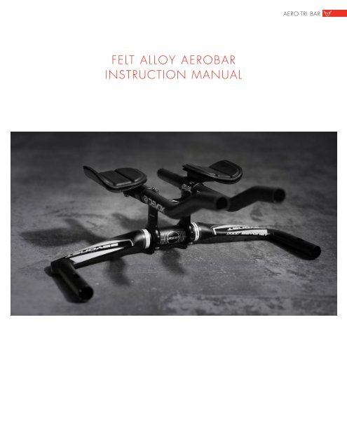
<strong>FELT</strong> <strong>ALLOY</strong> <strong>AEROBAR</strong><br />
<strong>INSTRUCTION</strong> <strong>MANUAL</strong><br />
AERO-TRI BAR
TABLE OF CONTENTS<br />
Introduction . . . . . . . . . . . . . . . . . . . . . . . . . . . . . . . . . . . . . . . . . . . . . . . . . . . . . . . . . .<br />
3<br />
Parts list . . . . . . . . . . . . . . . . . . . . . . . . . . . . . . . . . . . . . . . . . . . . . . . . . . . . . . . . . . 4 & 5<br />
Overview . . . . . . . . . . . . . . . . . . . . . . . . . . . . . . . . . . . . . . . . . . . . . . . . . . . . . . . .<br />
6 & 7<br />
Configuration Reference Chart . . . . . . . . . . . . . . . . . . . . . . . . . . . . . . . . . . . . . . . . . . . . .<br />
8<br />
Aerobar Assembly . . . . . . . . . . . . . . . . . . . . . . . . . . . . . . . . . . . . . . . . . . . . . . . . .<br />
Step 1: Stack Height & Riser Assembly . . . . . . . . . . . . . . . . . . . . . . . . . . . . . . . . .<br />
8 & 9<br />
9 & 10<br />
Step 2: Armrest Assembly . . . . . . . . . . . . . . . . . . . . . . . . . . . . . . . . . . . . . . . . .<br />
10 & 11<br />
Step 3: Final Assembly . . . . . . . . . . . . . . . . . . . . . . . . . . . . . . . . . . . . . . . . . . . . . . .<br />
Step 4: Cable Routing Instructions . . . . . . . . . . . . . . . . . . . . . . . . . . . . . . . . . . . . . . . .<br />
Notes & Dimension Log . . . . . . . . . . . . . . . . . . . . . . . . . . . . . . . . . . . . . . . . . . . . . . . . .<br />
12<br />
12<br />
13<br />
2
AERO-TRI BAR<br />
INTRODUCTION<br />
Thank you for purchasing the <strong>Felt</strong> aerobar system. Like all <strong>Felt</strong> products, this aerobar is engineered to offer maximum adjustability<br />
and dependability while being easy to use and service. Because this is a precision engineered product we ask you to take great care<br />
in its installation and use. Please apply quality grease to all bolts and always use a torque wrench when tightening all fasteners.<br />
If you are unsure about anything during the installing of this product, please seek the assistance of a qualified bicycle mechanic which<br />
you can find at any <strong>Felt</strong> Authorized dealer. For your local <strong>Felt</strong> dealer listings please consult our website.<br />
Limited Warranty: Handlebars<br />
Subject to the terms, conditions and limitations set forth below, <strong>Felt</strong> products are guaranteed against defects in materials and workmanship for one year from date of purchase from an authorized <strong>Felt</strong> Dealer. This warranty<br />
applies only to the original owner of <strong>Felt</strong> products and is not transferable to subsequent owners. This warranty does not cover a cracked handlebar or other damage due to crashes or other similar impacts. <strong>Felt</strong> alloy<br />
Handlebars have no implied lifespan due to the many variables that affect them, including the amount and type of use, as well as other conditions. It is the owner’s responsibility to have his/her <strong>Felt</strong> products including the<br />
handlebar inspected by a technician at an authorized <strong>Felt</strong> Dealer on a regular basis to detect any damage that may have occurred during normal use and immediately after a crash or other impact even if there is no visible<br />
damage. Limited Warranty Service: To obtain service under this warranty, the original purchaser must present the product along with the original, dated proof of purchase to an authorized <strong>Felt</strong> Dealer.<br />
Limit of Warranty: During the duration of this warranty, <strong>Felt</strong> <strong>Bicycles</strong>, LLC, will—at its sole discretion—either repair or replace any <strong>Felt</strong> product deemed by <strong>Felt</strong> to be defective. All <strong>Felt</strong> products should be regularly inspected<br />
by a technician at an authorized <strong>Felt</strong> Dealer for indications of potential failures. These are important safety checks and may help prevent accidents, bodily injury to the rider, and shortened product life cycles of <strong>Felt</strong> products.<br />
Not covered under limited warranty:<br />
• Normal wear and tear.<br />
• Any product improperly installed, assembled or maintained.<br />
• Any product that <strong>Felt</strong> determines has been modified or used with neglect to maintenance.<br />
• Any product used for stunt riding or similar activities, racing, commercial purposes or in any other manner for which they were not designed.<br />
• Damage, failure or loss resulting from causes other than manufacturing defects. This may include but is not limited to: theft, nonstandard or unapproved use, rider error, accident, abuse, neglect, or failure to follow<br />
applicable instructions or warnings.<br />
• Finish blemishes or damage due to exposure to the weather or to a chemical or other similar environment.<br />
• Labor costs associated with servicing, repairing or replacing the product.<br />
<strong>Felt</strong> <strong>Bicycles</strong>, LLC, makes no other warranties express or implied by operation of law or otherwise, including the warranties of merchantability and fitness for a particular purpose,<br />
which are limited in duration to those of the express warranties stated herein.<br />
<strong>Felt</strong> <strong>Bicycles</strong>, LLC, shall not be liable or responsible for direct, incidental or consequential damages including but not limited to damages for personal injury, property damage or<br />
economic losses, whether based on contract, warranty, negligence, product liability or any other theory.<br />
Some states do not allow the exclusion or limitation of damages or how long an implied warranty lasts so the above limitation/exclusion may not apply to you.
PARTS LIST<br />
QTY. SIZE - PART NAME PART<br />
4<br />
M6 x 35mm - Bolt<br />
4<br />
M6 x 30mm - Bolt<br />
8<br />
M6 x 25mm - Bolt<br />
8<br />
M6 x 20mm - Bolt<br />
10<br />
M6 x 15mm - Bolt<br />
4<br />
M5 x 12mm - Bolt<br />
40<br />
Fit Washer<br />
2<br />
Bracket Spacer<br />
2<br />
Armrest Washer<br />
2<br />
Threaded Nut<br />
1<br />
Narrow Fixed Bracket<br />
1<br />
Adjustable Bridge<br />
2<br />
Armrest<br />
4
AERO-TRI BAR<br />
QTY.<br />
SIZE - PART NAME<br />
PART<br />
1<br />
Basebar<br />
2<br />
Extension<br />
2<br />
Extension Plug<br />
2<br />
Extension Bracket<br />
2<br />
Armrest Bracket<br />
4<br />
Upper Bracket<br />
4<br />
Lower Bracket<br />
QTY.<br />
2<br />
2<br />
2<br />
2<br />
4<br />
SIZE<br />
40mm<br />
30mm<br />
20mm<br />
10mm<br />
5mm<br />
PART<br />
Threaded Spacer<br />
Threaded Spacer<br />
Threaded Spacer<br />
Non-Threaded<br />
Spacer<br />
Non-Threaded<br />
Spacer
OVERVIEW<br />
The below reference highlights the five main areas of adjustment that can be manipulated to achieve the desired<br />
configuration.<br />
1. Armpad position & angle<br />
2. Armpad fore & aft<br />
3. Arm pad width<br />
4. Extension width & angle<br />
5. Extension fore & aft<br />
6. Stack height<br />
7. Basebar orientation<br />
Below is a box that illustrates the range of common positions that can be acheived with the <strong>Felt</strong> aerobar system.<br />
Adjustment field<br />
6
OVERVIEW<br />
AERO-TRI BAR<br />
Further adjustment can be achieved by flipping the extension brackets 180 degrees to position the extensions closer<br />
together for riders who prefer a narrower position. See two images below for a demonstration.<br />
Shown below is an example of a low-stack configuration with a wide arm pad and extension position.<br />
35 or 40mm Stack Height<br />
The example shown directly below is configured in mid-stack height and utilizes a fixed bridge for stability.<br />
80 or 85mm Stack Height
z<br />
CONFIGURATION REFERENCE CHART<br />
BEFORE BEGINNING ASSEMBLY OF <strong>AEROBAR</strong>, READ THE CHART AND NOTES ON STACK HEIGHT BELOW.<br />
If you know your dimensions you require while riding a TT/TRI bicycle, the chart below will help you quickly identify the<br />
hardware required to achieve your desired stack height.<br />
If you do not know the dimensions you require, <strong>Felt</strong> recommends getting fitted by a qualified fit specialist.<br />
Stack Height (c-c)<br />
Threaded Spacer<br />
Non-threaded config.<br />
Fit Washers<br />
Top Bolts (mm)<br />
Bottom Bolts (mm)<br />
Threaded Nut<br />
35 X X 2 20 X<br />
40 X 5mm 4 25 X<br />
45 X 10mm 4 30 X<br />
50 X 5mm +10mm 6 35 X<br />
55 20 X 4 20 15<br />
60 20 5mm or Fixed or Adj. Bridge 6 20 15<br />
65 20 Adjustable Bridge + 5mm 8 30 115<br />
70 30 Fixed Bridge or Adj. Bridge 6 30 15<br />
75 30 Fixed Bridge + 5mm or<br />
Adjustable Bridge + 5mm<br />
8 30 15<br />
80 30 Adjustable Bridge +10mm 8 35 15<br />
80 40 Fixed Bridge or Adj. Bridge 6 35 15<br />
85<br />
85<br />
90*<br />
40<br />
40<br />
40<br />
Fixed Bridge + 5mm or<br />
Adjustable Bridge + 5mm<br />
Fixed Bridge + 10mm or<br />
Adjustable Bridge + 10mm<br />
Fixed Bridge + 10mm + 5mm or<br />
Adjustable Bridge + 10mm + 5mm<br />
8<br />
8<br />
8<br />
35<br />
35<br />
35<br />
15<br />
15<br />
25<br />
1<br />
1<br />
1<br />
1<br />
Notes about table to left:<br />
*In this configuration the 5mm<br />
spacer must be installed under the<br />
40mm threaded spacer and longer<br />
bottom bolts must be used.<br />
An assembly with stack height of<br />
50mm will be used as an example<br />
in the following instructions.<br />
8<br />
Before beginning assembly, choose your<br />
preferred orientation of the base bar. The<br />
diagram to the left shows the base bar<br />
orientation upward (for rise) +20mm and<br />
downward (for drop) -20mm.
Step 1: Stack Height & Riser Assembly<br />
AERO-TRI BAR<br />
Stack Height (c-c)<br />
Threaded Spacer<br />
Non-threaded config.<br />
Fit Washers<br />
Top Bolts (mm)<br />
Bottom Bolts (mm)<br />
Threaded Nut<br />
Option A<br />
50 X 5mm +10mm 6 35 X<br />
1<br />
- One extension<br />
- Two upper bolts (35mm)<br />
- One extension bracket<br />
- One bracket spacer*<br />
- Stack height spacers (10mm + 5mm)<br />
- Fit washers (6)**<br />
- One upper bracket<br />
- Threaded nut (1 for low stack configurations when only upper bolts are used)<br />
Option A. See the diagram at right to assist in building the first stack assembly.<br />
The example to the right is a low-stack configuration and thus does NOT require<br />
a bridge.<br />
Stack Height (c-c)<br />
Threaded Spacer<br />
Non-threaded config.<br />
Fit Washers<br />
Top Bolts (mm)<br />
Bottom Bolts (mm)<br />
60 20 5mm or fixed or adj. bridge 6 20 15<br />
Threaded Nut<br />
Option B<br />
- One Extension<br />
- Two upper bolts (20mm)<br />
- One extension bracket<br />
- One bracket spacer*<br />
- Narrow fixed bridge<br />
- Fit washers (6)**<br />
- Stack height spacers (20mm + 5mm)<br />
- One upper bracket<br />
- Lower bolts (2)<br />
Option B. This sample shows a stack assembly that requires a total of 4 bolts, two<br />
of which enter the underside of the upper bracket and thread into the threaded<br />
spacer, and the two top bolts enter the extension bracket and thread into the<br />
threaded spacer. Tighten to 6Nm.
*BRACKET SPACER<br />
Insert bracket spacer into the slots of the extension bracket, aligning the holes,<br />
leaving the long, curved edge flush with the edge of the extension bracket slot<br />
exactly as shown to the right.<br />
**FIT WASHERS<br />
Begin with pressing the fit washers into the recessed holes.<br />
Sandwitch the fit washer between the<br />
bolt, spacer/bridge and a threaded<br />
spacer. Tighten the bolt until the fit<br />
washer is pressed in. Unthread the<br />
bolt and assemble.<br />
Threaded nut<br />
Threaded spacer<br />
Step 2: Arm Rest Assembly<br />
To complete the arm rest assembly, you will need the following:<br />
- Two 12mm arm rest bolts<br />
- One arm rest washer<br />
- One arm rest<br />
- One arm rest bracket<br />
- One 15mm bolt<br />
Begin by taking an arm rest bracket and thread a 15mm bolt into the<br />
underside and finger-tighten to keep in place. Place the arm rest washer and<br />
use two arm rest bolts to fasten in desired position. Finally, slip the arm rest<br />
assembly over the extension and tighten the 15mm bolt to 7Nm.<br />
See diagram on following page for the four acceptable configurations.<br />
10
AERO-TRI BAR<br />
Possible armrest configurations<br />
Notice the diameters of the six holes in the arm rest are larger than the<br />
diameter of the bolt shaft. This allows for further fine-tuning to achieve<br />
desired arm pad angle. See below for illustration.<br />
Counter-Clockwise Rotation<br />
Clockwise Rotation<br />
This image shows the stack assembly and armrest assembly properly<br />
mounted on an extension. (Actual placement of assemblies in relation to<br />
the extension will vary)
Step 3: Final Assembly<br />
Step 4: Cable Routing<br />
Routing the brake and shifter cables can be<br />
made easier by following these suggested steps:<br />
1. Insert the steel inner cable, starting at the<br />
rear of the bar.<br />
2. Route the steel inner cable though the bar<br />
until it exits the appropriate hole.<br />
3. Starting at the end nearest the grip area of<br />
the bar, slip the cable housing over the cable<br />
and continue to advance the cable housing<br />
through the bar (using the cable as a guide)<br />
until it exits the hole you inserted the cable into.<br />
12
Notes & Dimension Log<br />
AERO-TRI BAR<br />
Your Dimensions:<br />
Name ______________________ Date __________ Stack height __________mm Arm pad width __________mm<br />
Extension width __________mm Stem Length/rise __________mm/__________degrees Frame______________________<br />
Notes:<br />
Your dimensions:<br />
Name ______________________ Date __________ Stack height __________mm Arm pad width __________mm<br />
Extension width __________mm Stem Length/rise __________mm/__________degrees Frame______________________<br />
Notes: