Vinyl Acetate Monomer Process 10
Vinyl Acetate Monomer Process 10
Vinyl Acetate Monomer Process 10

Create successful ePaper yourself
Turn your PDF publications into a flip-book with our unique Google optimized e-Paper software.
287<br />
<strong>10</strong><br />
<strong>Vinyl</strong> <strong>Acetate</strong> <strong>Monomer</strong> <strong>Process</strong><br />
<strong>10</strong>.1<br />
Basis of Design<br />
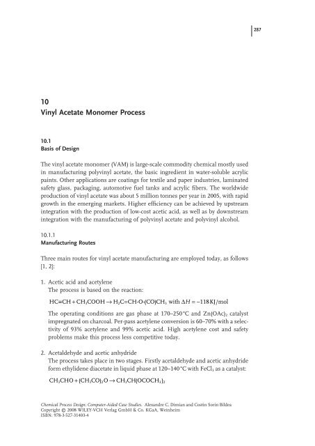
The vinyl acetate monomer (VAM) is large - scale commodity chemical mostly used<br />
in manufacturing polyvinyl acetate, the basic ingredient in water - soluble acrylic<br />
paints. Other applications are coatings for textile and paper industries, laminated<br />
safety glass, packaging, automotive fuel tanks and acrylic fibers. The worldwide<br />
production of vinyl acetate was about 5 million tonnes per year in 2005, with rapid<br />
growth in the emerging markets. Higher efficiency can be achieved by upstream<br />
integration with the production of low - cost acetic acid, as well as by downstream<br />
integration with the manufacturing of polyvinyl acetate and polyvinyl alcohol.<br />
<strong>10</strong>.1.1<br />
Manufacturing Routes<br />
Three main routes for vinyl acetate manufacturing are employed today, as follows<br />
[1, 2] :<br />
1. Acetic acid and acetylene<br />
The process is based on the reaction:<br />
HC≡ CH + CH COOH → H C= CH-O-( CO) CH with ∆H =− KJ/mol<br />
3 2 3 118<br />
The operating conditions are gas phase at 170 – 250 ° C and Zn(OAc) 2 catalyst<br />
impregnated on charcoal. Per - pass acetylene conversion is 60 – 70% with a selectivity<br />
of 93% acetylene and 99% acetic acid. High acetylene cost and safety<br />
problems make this process less competitive today.<br />
2. Acetaldehyde and acetic anhydride<br />
The process takes place in two stages. Firstly acetaldehyde and acetic anhydride<br />
form ethylidene diacetate in liquid phase at 120 – 140 ° C with FeCl 3 as a catalyst:<br />
CH CHO + ( CH CO) O →CH CH( OCOCH )<br />
3 3 2 3 3 2<br />
Chemical <strong>Process</strong> Design: Computer-Aided Case Studies. Alexandre C. Dimian and Costin Sorin Bildea<br />
Copyright © 2008 WILEY-VCH Verlag GmbH & Co. KGaA, Weinheim<br />
ISBN: 978-3-527-31403-4
288 <strong>10</strong> <strong>Vinyl</strong> <strong>Acetate</strong> <strong>Monomer</strong> <strong>Process</strong><br />
In the second step the intermediate decomposes at 120 ° C with acid catalyst:<br />
CH CH( OCOCH ) → H C= CH-O-( CO)<br />
CH + CH COOH<br />
3 3 2 2 3 3<br />
Note that this process may rely completely on renewable raw materials.<br />
3. Acetic acid, ethylene and oxygen<br />
This route dominates today and it will be adopted in this project. In older technologies<br />
the reaction was conducted in liquid phase at 1<strong>10</strong> – 130 ° C and 30 – 40<br />
bar in the presence of a redox catalyst PdCl 2 /CuCl 2 , but corrosion raised problems.<br />
Modern processes operate in gas phase with Pd - based catalysts. A highly<br />
undesired secondary reaction is the combustion of ethylene to CO 2 . With<br />
modern Pd/Au catalysts the selectivity may reach 94%, based on ethylene and<br />
98 – 99% based on acetic acid. The removal of CO 2 – usually by a wash with hot<br />
KOH solution – negatively affects the overall economics. Hoechst/Celanese and<br />
Bayer/DuPont are the most widespread processes, the main difference being<br />
in the formulation of the catalyst. With respect to reaction engineering a multitubular<br />
fixed - bed reactor is employed, where the operational difficulty is<br />
mastering the occurrence of excessive temperature rise (hot spot). Recently,<br />
fluid - bed reactor technology was developed with better productivity and 30%<br />
lower investment [13] .<br />
Searching for low - cost acetic acid sources is important since this takes about<br />
70 wt% in the end product. From this viewpoint two processes developed by<br />
the Halcon Company can be mentioned [2] :<br />
1. Integration of vinyl acetate and ethylene glycol manufacturing through the<br />
intermediate 1,2 - diacetoxyethane.<br />
2. Hydrogenative carbonylation of methyl acetate to 1,1 - diacetoxyethane followed<br />
by cleavage to vinyl acetate and acetic acid. Only syngas is involved as raw<br />
materials.<br />
<strong>10</strong>.1.2<br />
Problem Statement<br />
The project deals with a VAM plant capacity of <strong>10</strong>0 kton per year for an effective<br />
operation time of 8400 h. The process will be based on the acetoxylation of ethylene<br />
conducted in gas phase in the presence of a palladium - based solid catalyst. The<br />
case study will tackle the problem of process synthesis and energy integration,<br />
as well as the dynamics and control for ensuring flexibility in production rate of<br />
± <strong>10</strong>%, while preserving safety and environment protection.<br />
Table <strong>10</strong>.1 presents typical specifications for a polymerization - grade product, as<br />
well as some physical properties. Prohibited impurities refer to inhibitors (crotonaldehyde,<br />
vinyl acetylene), chain - transfer agents (acetic acid, acetaldehyde, acetone)<br />
and polymerizable species (vinyl crotonate), while methyl and ethyl acetate impurities<br />
are tolerated.
<strong>10</strong>.2 Reactions and Thermodynamics 289<br />
Table <strong>10</strong>.1 Properties for industrial vinyl acetate [1] .<br />
Property<br />
Value<br />
Molecular weight 86.09<br />
<strong>Vinyl</strong> ester content ≥ 99.9%<br />
Distillation range (<strong>10</strong>1.3 kPa)<br />
72 – 73 ° C<br />
Freezing point<br />
− 93 ° C<br />
Water<br />
Max. 400 ppm<br />
Acid content (acetic acid)<br />
Max 50 ppm<br />
Acetaldehyde<br />
Max <strong>10</strong>0 ppm<br />
Inhibitor content<br />
3 – 5 ppm<br />
n 20 D 1.369<br />
d 20 20 0.93<br />
Liquid viscosity at 20 ° C<br />
0.41 cP<br />
Solubility VAM - water/water - VAM at 25 ° C 0.9%/2.3%<br />
Solubility in organic solvents<br />
complete<br />
Upper/lower explosion limit vapor in air at 20 ° C<br />
2.6/13.4% vol.<br />
<strong>10</strong>.1.3<br />
Health and Safety<br />
<strong>Vinyl</strong> acetate is slightly or moderately toxic to humans and animals. The vapor<br />
irritates the eyes starting with 20 ppm, while the detection threshold is reported<br />
to be about 0.5 ppm. Released into the environment the vinyl acetate evaporates<br />
easily, being degraded rapidly by photochemical reactions, as well as biodegraded<br />
by either anaerobic or aerobic mechanisms. Therefore, the bioaccumulation of<br />
vinyl acetate in the ecosphere is unlikely.<br />
<strong>Vinyl</strong> acetate is dangerous when exposed to heat, flame or oxidizers, and as a<br />
consequence, it requires adhering to the safety measures when stored or manipulated<br />
by operators. The same precaution is valid for the raw materials. Ethylene is<br />
highly explosive in mixture with oxygen, the explosion limit being at <strong>10</strong>% vol. The<br />
acetic acid is a highly toxic and corrosive substance. Stainless steel of Cr/Ni/Co<br />
type is employed for operations involving acetic - acid solutions in boiling conditions,<br />
but normal stainless steel may be used for vapor - phase operations.<br />
<strong>10</strong>.2<br />
Reactions and Thermodynamics<br />
<strong>10</strong>.2.1<br />
Reaction Kinetics<br />
The manufacturing of vinyl acetate by the oxyacetylation of ethylene is described<br />
by the following stoichiometric reaction:
290 <strong>10</strong> <strong>Vinyl</strong> <strong>Acetate</strong> <strong>Monomer</strong> <strong>Process</strong><br />
C H + CH COOH + 05 . O → C H OOCCH + H O<br />
(<strong>10</strong>.1)<br />
2 4 3 2 2 3 3 2<br />
Gas - phase reaction is preferred because of better yield and less corrosion<br />
problems.<br />
The combustion of ethylene to CO 2 is a highly undesired secondary reaction<br />
since it lowers the yield and complicates the removal of the reaction heat:<br />
CH + 3O → 2CO + 2HO<br />
(<strong>10</strong>.2)<br />
2 4 2 2 2<br />
Note that the standard heat of reaction is of − 176.2 and − 1322.8 kcal/kJ per<br />
mol for vinyl acetate and ethylene combustion, respectively. If both reactions are<br />
considered the mean exothermal effect may be estimated at about − 250 kJ/mol<br />
[1] .<br />
The catalyst plays a crucial role in technology. Previously, catalysts were based<br />
on palladium of 1 to 5 wt% impregnated on silica with alkali metal acetates as<br />
activators. Modern catalysts employ as enhancers noble metals, mostly gold. A<br />
typical Bayer - type catalyst consists of 0.15 – 1.5 wt% Pd, 0.2 – 1.5 wt% Au, 4 – <strong>10</strong> wt%<br />
KOAc on spherical silica particles of 5 mm diameter [14] . The reaction is very<br />
fast and takes place mainly inside a thin layer on the particle surface (egg - shell<br />
catalyst).<br />
Typical catalyst lifetime is 1 – 2 years. Preferred operation conditions are temperatures<br />
around 150 to 160 ° C and pressures 8 to <strong>10</strong> bar. Hot spots above 200 ° C<br />
lead to permanent catalyst deactivation. The reactant ratio should ensure an excess<br />
of ethylene to acetic acid of about 2 : 1 to 3 : 1. Due to an explosion danger the<br />
oxygen concentration in the reaction mixture should be kept below 8%, based on<br />
an acetic - acid - free mixture [1] . The above figures formulate design constraints in<br />
the present project. In addition, a small amount of water in the initial mixture<br />
could be necessary for catalyst activation.<br />
Because of the highly exothermic effect, measures to moderate the temperature<br />
increase are necessary, such as the dilution of the reaction mixture with some inert<br />
gas. Because of selectivity and heat - removal constraints the reactor is designed at<br />
low per - pass conversion, generally 15 – 35% for the acetic acid and 8 – <strong>10</strong>% for<br />
ethylene [2] .<br />
Analyzing the mechanism of the catalytic chemical reaction allows the identification<br />
of the major factors that could affect the reactor design. Early in 1970 Samanos<br />
et al . [11] demonstrated that the reaction mechanism in gas phase shows great<br />
similarity to a liquid - phase reaction. This viewpoint has been adopted by a more<br />
general concept of supported liquid - phase catalysis (SLPC), in which the same<br />
reaction mechanism may be employed to explain both homogeneous and heterogeneous<br />
processes. A salient example is the class of selective oxidation reactions,<br />
including the present ethylene acetoxidation [12] . Under typical plant conditions,<br />
the adsorption of acetic acid and water on the catalyst can be substantial, the acetic<br />
acid forming about three monolayers. The promoter, in general an alkali metal<br />
acetate, plays an important role too. For example, KOAc gives a salt with water<br />
with the melting point at 148 ° C. This salt contributes to the formation of the acetic
acid layer, as described by the reaction KOAc + AcOH → KH(OAc) 2 , which further<br />
prevents the combustion of ethylene. Moreover, the KOAc enhances the formation<br />
of actives centers through the solvatation of palladium complexes as Pd(OAc) 2 +<br />
KOAc → KPd(OAc) 3 . Therefore, a probable reaction mechanism could be formulated<br />
as follows:<br />
Pd + 05 . O + 2AcOH ↔ Pd( OAc) + H O<br />
(1)<br />
2 2 2<br />
Pd( OAc) + AcO − ↔Pd( OAc)<br />
− (2)<br />
2 3<br />
<strong>10</strong>.2 Reactions and Thermodynamics 291<br />
−<br />
−<br />
Pd( OAc) 3 + C 2 H 4 ↔ VAM + AcOH + AcO + Pd<br />
(3)<br />
As a result, from a reactor - design viewpoint the reaction kinetics is not sensitive<br />
to the concentration of the acetic acid, but the presence of some water is necessary<br />
to activate the catalyst. On the contrary, ethylene and oxygen are involved in kinetics<br />
through a complex adsorption/surface - reaction mechanism. This behavior was<br />
confirmed by both academic and industrial research [8, 9] .<br />
Modern catalysts for vinyl - acetate synthesis contain Au in the chemical formulation,<br />
which manifests in much higher activity and selectivity. This is reflected by<br />
fundamental changes in the kinetics, such as for example switching the reaction<br />
order of ethylene from negative to positive [8] . As a consequence, in more recent<br />
studies the formation of vinyl acetate can be described conveniently by a power - law<br />
kinetics involving only ethylene and oxygen:<br />
1<br />
r k p p<br />
α β<br />
VA = 1<br />
1 CH 2 4 O2<br />
(<strong>10</strong>.3)<br />
The exponent α 1 is 0.35 – 0.38 and β 1 0.18 – 0.21 indicating strong adsorption limitations.<br />
The reaction constant is given by k 1 = A 1 exp( − E 1 / RT ) in which the energy<br />
of activation depends on the Pd content, for example 39 kJ/mol for Pd 1% and<br />
17.3 kJ/mol for Pd 5%.<br />
Similar kinetics has been found to describe the secondary combustion reaction,<br />
but with reaction orders very different from the main reaction:<br />
2<br />
r k p p<br />
α β2<br />
CO2 = 2 CH 2 4 O2<br />
(<strong>10</strong>.4)<br />
Table <strong>10</strong>.2 presents the kinetic information for the main reactions, in which the<br />
frequency factors have been calculated from turnover - frequency (TOF) data [8, 9] .<br />
This term, borrowed from enzymatic catalysis, quantifies the specific activity of<br />
a catalytic center. By definition, TOF gives the number of molecular reactions<br />
or catalytic cycles occurring at a center per unit of time. For a heterogeneous catalyst<br />
the number of active centers can be found by means of sorption methods. Let<br />
us consider that the active sites are due to a metal atom. By definition [15] we<br />
have:<br />
volumetric rate of reaction moles_A<br />
TOF = =<br />
number of center/volume l_cat × s<br />
l_cat<br />
moles_Me<br />
= s −1<br />
(<strong>10</strong>.5)
292 <strong>10</strong> <strong>Vinyl</strong> <strong>Acetate</strong> <strong>Monomer</strong> <strong>Process</strong><br />
The catalyst is characterized by the metal weight fraction w Me with MW Me the<br />
atomic weight, the metal dispersion coefficients D giving the fraction of active<br />
centers, and ρ cat the grain catalyst density. By replacing into the relation (<strong>10</strong>.5) the<br />
following formula can be obtained for the calculation of TOF from kinetic<br />
experiments:<br />
TOF =<br />
moles_A/s<br />
l_cat<br />
g_Me<br />
g_cat<br />
1<br />
D<br />
×<br />
MW<br />
Me<br />
g_cat<br />
l_cat<br />
=<br />
⎛ D<br />
RA<br />
wMe×<br />
⎝ MW<br />
Me<br />
⎞<br />
⎠<br />
(<strong>10</strong>.6)<br />
Conversely, transforming TOF into reaction rate data can be done with the<br />
relation:<br />
D<br />
− rA<br />
= TOF × wMe× × ρ cat<br />
(<strong>10</strong>.7)<br />
MW<br />
Me<br />
As an example, let us consider the reported value TOF = 6.5 × <strong>10</strong> – 3 s − 1 . Catalyst<br />
data are: ρ cat = <strong>10</strong>00 g/l, MW Pd = <strong>10</strong>6.4, w Pd = 0.01, D = 0.4. One gets<br />
− r A = 6.5 × <strong>10</strong><br />
– 3<br />
× 0.01 × (0.4/<strong>10</strong>6.4) × <strong>10</strong>00 = 2.44 × <strong>10</strong><br />
– 4<br />
moles VA/l_cat/s =<br />
2.<strong>10</strong> × <strong>10</strong><br />
– 2<br />
g/l/s = 7.52 × <strong>10</strong> – 2 kg/l/h. Note that this TOF value is obtained at a<br />
low partial pressure of ethylene. In industrial conditions the pressure is an order<br />
of magnitude higher. Thus, the reaction rate would be about 0.7 kg/l/h. This<br />
value is in agreement with STY reported in some recent patents. For example,<br />
a modern Pd - gold catalyst on supported 4 – 6 mm silica spheres (patent US<br />
649229931) gives a space - time yield (STP) of 700 g VAM/l/h and a selectivity of<br />
92 – 94% at 150 ° C and 7.8 bar with a gas mixture of ethylene 53.1/acetic acid<br />
<strong>10</strong>.4/oxygen 7.7 and inert 28.6 (vol.%).<br />
Note that expressing the catalyst activity in terms of TOF allows tailoring the<br />
catalyst activity to the requirements of process design. Because the activation<br />
energy remains constant, the only affected parameter is the pre - exponential factor<br />
A , which in turn is proportional to the weight fraction of the active center,<br />
in this case the metal. Table <strong>10</strong>.2 shows two situations. In the first case the pre -<br />
exponential factor is taken from the original TOF data, which corresponds to a fast<br />
Table <strong>10</strong>.2 Kinetic parameters for VAM synthesis over a Pd/Au/SiO 2 catalyst [8, 9] .<br />
Reactions<br />
Power - law<br />
kinetics<br />
Kinetic constants<br />
C 2 H 4 O 2 E (J/mol) A 1 A 2<br />
C 2 H 4 + CH 3 COOH + 0.5O 2 0.36 0.20 15000 2.65 × <strong>10</strong> –4 –5<br />
7.95 × <strong>10</strong><br />
→ C 2 H 3 OOCCH 3 + H 2 O<br />
C 2 H 4 + 3O 2 → 2CO 2 + 2H 2 O − 0.31 0.82 2<strong>10</strong>00 7.50 × <strong>10</strong> –4 –4<br />
2.25 × <strong>10</strong><br />
Reaction rate in mol/(liter catalyst · s).
Table <strong>10</strong>.3 Typical operation conditions for the VAM reactor [14] .<br />
<strong>10</strong>.2 Reactions and Thermodynamics 293<br />
Parameter<br />
Typical values<br />
Pressure<br />
5 – 12 atm<br />
Temperature<br />
140 – 180 ° C<br />
GHSV 2000 – 4000 h − 1<br />
Reaction mixture Composition mol% Conversion % Selectivity<br />
Ethylene 50 8 – <strong>10</strong> 91 – 94<br />
Acetic acid <strong>10</strong> – 20 15 – 30 > 99<br />
Oxygen 6 – 8 60 – 70 60 – 70<br />
CO 2 <strong>10</strong> – 30 – –<br />
Inert (balance) N 2 or Ar – –<br />
catalyst. Preliminary simulation showed that in this case the occurrence of hot<br />
spot is very likely. For this reason in the second case the catalyst activity is lowered<br />
by a factor of three, by less metal impregnation. This catalyst is adopted for the<br />
reactor design and flowsheet simulation.<br />
Table <strong>10</strong>.3 presents typical operation conditions for a multitubular chemical<br />
reactor. Higher pressure has a positive effect on productivity, but affects the selectivity<br />
negatively since increased adsorption of ethylene on the catalytic sites favors<br />
the combustion reaction. The reaction temperature should be above 150 ° C in<br />
order to bring the salt activator into the molten state. However, temperatures<br />
higher than 150 ° C have only a moderate effect on the reaction rate because of low<br />
activation energy, but it may decrease considerably the selectivity. Preventing the<br />
hot spot and operating close to isothermal conditions is desirable. This may be<br />
achieved by diluting the catalyst in the entry zone and/or by manipulating the<br />
pressure of the raising steam. But most of all, by means of compositional and<br />
structural effects there is the possibility to modify the activity of a particular catalyst<br />
so as to fulfil an optimal reactor design.<br />
<strong>10</strong>.2.2<br />
Physical Properties<br />
Table <strong>10</strong>.4 presents basic physical properties of the key components. By boiling<br />
point the acetic acid is the heaviest. <strong>Vinyl</strong> acetate is a light species with a normal<br />
boiling point at 72.6 ° C. Of major interest is the low - boiler heterogeneous azeotrope<br />
vinyl acetate/water with 25 mol% water and nbp at 65.5 ° C. The very low<br />
solubility of vinyl acetate in water, less than 1 wt%, is to be noted. Low reciprocal<br />
solubility can be exploited for separating the mixtures vinyl acetate/water by azeotropic<br />
distillation. In addition the densities of water and vinyl acetate are sufficiently<br />
distinct to ensure good liquid – liquid decanting.
294 <strong>10</strong> <strong>Vinyl</strong> <strong>Acetate</strong> <strong>Monomer</strong> <strong>Process</strong><br />
Table <strong>10</strong>.4 Basic physical properties of the main components.<br />
Name Ethylene Acetic acid VAM Water<br />
Molecular formula C 2 H 4 C 2 H 4 O 2 C 4 H 6 O 2 H 2 O<br />
Molecular weight 28.05 60.05 86.09 18.015<br />
Normal boiling point, K 162.42 391.04 345.95 373.15<br />
Melting point, K <strong>10</strong>4 289.93 180.35 273.15<br />
Critical temperature, K 282.34 594.45 519.15 674.14<br />
Critical pressure, bar 50.41 57.90 40.3 220.64<br />
3<br />
Critical volume, cm /mol 131.1 171.0 270 55.95<br />
Liquid density, kg/m 3 ( ° C) 577 ( − 1<strong>10</strong>) <strong>10</strong>49.2 (20) 934 (20) <strong>10</strong>00 (15)<br />
Vaporization heat at nbp, kJ/mol 13.553 23.7 31.49 40.66<br />
<strong>10</strong>.2.3<br />
VLE of Key Mixtures<br />
It can be anticipated that the liquid - separation system should handle the mixture<br />
vinyl acetate/acetic acid/water. Figure <strong>10</strong>.1 displays the residue curve map at 1 atm<br />
calculated by Aspen Split [16] with the thermodynamic NRTL/HOC and VLLE<br />
option. The phase equilibrium is dominated by the binary heterogeneous azeotrope<br />
vinyl acetate/water with the composition 0.745/0.255 mol% or 0.933/0.0667<br />
wt% and boiling points at 65.6 ° C. It may be observed that the relative position of<br />
the azeotrope, as well as reciprocal solubility and the tie - line direction depend on<br />
the compositional coordinate, in molar or mass fractions, because of the large<br />
difference in the molar weight of the two components. The residue curve map<br />
suggests as a separation strategy the distillation in top of the VAM/water azeotrope<br />
followed by the separation of VAM by L – L decanting, while the acetic acid can be<br />
obtained as bottom product.<br />
<strong>10</strong>.3<br />
Input – Output Analysis<br />
The selection of raw materials takes into account the price variation versus purity,<br />
with constraints on undesired species. Table <strong>10</strong>.5 shows the choice. Acetic acid is<br />
of high purity with small amounts in acetaldehyde and formic acid. Ethylene is of<br />
high purity too, with severe specifications on CO and sulfur in order to protect the<br />
catalyst, but small amounts of ethane are allowed.<br />
<strong>10</strong>.3.1<br />
Preliminary Material Balance<br />
Taking the acetic acid as reference, its molar feed is <strong>10</strong>0 000/8400/86 = 138.43 kmol/<br />
h, which is rounded further to 140 kmol/h. A key decision regards the selectivity.
<strong>10</strong>.3 Input-Output Analysis 295<br />
Figure <strong>10</strong>.1 Residue curve map of the mixture vinyl acetate/acetic acid/water.<br />
Table <strong>10</strong>.5 Purity specifi cations for the raw materials.<br />
Ethylene<br />
Acetic acid<br />
Purity 99.9% 99.5%<br />
Impurities Ethane < 1% Formic acid 50 ppm<br />
CO 2 – <strong>10</strong> ppm<br />
Acetaldehyde 50 ppm<br />
Sulfur 1 – <strong>10</strong> ppm Water < 0.5%
296 <strong>10</strong> <strong>Vinyl</strong> <strong>Acetate</strong> <strong>Monomer</strong> <strong>Process</strong><br />
Table <strong>10</strong>.6 Ideal input/output material balance.<br />
Input<br />
Output<br />
kmol/h kg/h kmol/h kg/h<br />
C 2 H 4 148.936 4170.213<br />
Acetic acid 140.000 8400.000<br />
O 2 96.809 3097.872<br />
VAM 140.000 12 040.000<br />
Water 157.872 2841.702<br />
CO 2 17.872 786.383<br />
Total 385.745 15 668.085 315.745 15 668.085<br />
In a preliminary stage we select a value of 94%, at the upper limit but realistic for<br />
modern catalysts. We deliberately set zero targets for losses. With this assumption<br />
the preliminary input/output material balance looks as in Table <strong>10</strong>.6 . Some observations<br />
of significance for design may be immediately drawn. Thus, the large<br />
amount of wastewater will involve non - negligible costs for neutralization and biological<br />
treatment. Similarly, the process develops inherently CO 2 . Therefore, some<br />
ecological penalties have to be taken into account when estimating the economic<br />
potential.<br />
<strong>10</strong>.4<br />
Reactor/Separation/Recycles<br />
The kinetic analysis has shown that because of incomplete conversion two recycles<br />
have to be considered, for both ethylene and acetic acid. Preferably, the recycle<br />
policy should ensure an ethylene/acetic acid ratio of about three. A strong safety<br />
constraint is the concentration of oxygen in the reaction mixture. In general, the<br />
oxygen concentration at the reactor inlet should be below 8 vol% in order to avoid<br />
ignition, based on an acetic - acid - free mixture [1] . Note that in the stoichiometric<br />
mixture this is of 20%. The presence of a gaseous inert is recommended for better<br />
safety and control of the reactor temperature. Some reports indicate the use of<br />
ethane, since this is present as impurity in the fresh feed [6] , but this solution is<br />
not adopted here. Since CO 2 is produced by reaction in large amount its use as an<br />
inert would be the most economical. Indeed, several technology reports indicate<br />
this possibility in an amount of <strong>10</strong> – 30% vol [2, 14] . However, since CO is a catalyst<br />
poison its presence in the recycled gas has to be prevented.<br />
The chemical reactor will be designed in the context of a recycle system, as<br />
explained in Chapters 2 and 4 . The strategy is fixing the flow rate and composition<br />
of the reactor - inlet mixture at values that are compatible with the operation requirements<br />
of the catalyst, as given in Table <strong>10</strong>.3 , for example 50% mol C 2 H 4 , 20% mol<br />
acetic acid, 6% mol oxygen and 24% mol CO 2 . Figure <strong>10</strong>.2 presents the simulation
<strong>10</strong>.4 Reactor/Separation/Recycles 297<br />
Figure <strong>10</strong>.2 Design of the reactor for vinyl - acetate manufacturing in a recycle system.<br />
flowsheet with a PFR reactor and black - box separation unit, as well as with recycles<br />
for the gas (ethylene and CO 2 ) and liquid (acetic acid). All other components,<br />
namely VAM, water and byproduct CO 2 , are lumped into a product stream sent<br />
to further separation.<br />
The reactor is of the heat - exchanger type with catalyst and tubes and rising steam<br />
outside. In this project we consider spherical catalyst particles of 5 mm diameter<br />
and a bed void fraction of 45%, which offers a good trade - off between efficiency<br />
and lower pressure drop. The gas inlet pressure is <strong>10</strong> bar. We aim at a pressure<br />
drop less than 15% of the operating pressure, namely a maximum of 1.5 bar.<br />
For predesign calculations we consider a gas velocity of 0.5 m/s [4] . Mean physical<br />
properties for the above reaction mixture are: density 11.5 kg/m 3 , viscosity 1.5<br />
× <strong>10</strong> − 5 N s/m 2 , thermal conductivity 2.9 × <strong>10</strong> − 2 W/m K. The calculation of the heat -<br />
transfer coefficient follows the relations given in Chapter 5 . Applying the relation<br />
(5.9) leads to Re p = 2090 and Nu = 412, from which the partial heat - transfer coefficient<br />
on the gas side is α w = 350 W/m K. Taking into account other thermal<br />
resistances we adopt for the overall heat - transfer coefficient the value 250 W/m 2 K.<br />
For the cooling agent we consider a constant temperature of 145 ° C, which is 5 ° C<br />
lower than the inlet reactor temperature. This value is a trade - off between the<br />
temperature profile that avoids the hot spot and the productivity.<br />
By using the kinetic data given in Table <strong>10</strong>.2 (slow catalyst with pre - exponential<br />
factor A 2 ) the simulation leads to the following reactor design: 4900 tubes of internal<br />
diameter of 37 mm and 7.5 m length. The pressure drop calculated by the<br />
Ergun relation gives 0.93 bar, under the constraint of 1.5 bar.<br />
Table <strong>10</strong>.7 presents the stream table around the chemical reactor. As mentioned<br />
above, the inlet mixture is fixed because of control requirements. In this way, the<br />
outlet reflects the transformation of composition due to the chemical reactor. The<br />
molar conversions for ethylene and acetic acid are in agreement with industrial<br />
data. The amount of CO 2 formed by reaction is quite limited, denoting good<br />
catalyst selectivity; only about 11% from ethylene is consumed by combustion,<br />
the rest, 89%, going into vinyl acetate. Finally, the computation gives a catalyst<br />
productivity of 326.6 kg VAM/m 3 - catalyst · h.<br />
Note that other designs are possible using other values for the activity of that<br />
catalyst and the rate of heat removal. The challenge is to find a temperature profile
298 <strong>10</strong> <strong>Vinyl</strong> <strong>Acetate</strong> <strong>Monomer</strong> <strong>Process</strong><br />
Table <strong>10</strong>.7 Stream table around the chemical reactor.<br />
Mole flow kmol/h Reactor inlet Reactor outlet Conversion<br />
C 2 H 4 1450 1291.04 0.<strong>10</strong>9<br />
O 2 180 76.97 0.572<br />
CO 2 750 768.84<br />
<strong>Vinyl</strong> acetate 0 149.54<br />
H 2 O 0 168.38<br />
Acetic acid 600 450.46 0.249<br />
Figure <strong>10</strong>.3 Profi les for two catalysts and different reactor confi guration.<br />
that preserves the catalyst integrity but ensures high productivity and selectivity.<br />
Figure <strong>10</strong>.3 shows a comparison of the temperature profiles with the actual catalyst<br />
(2) against a fast catalyst (1), which is three times faster, as described by the values<br />
in Table <strong>10</strong>.2 . The number of tubes is reduced from 4900 to 2590, and the length<br />
from 8 to 4 m. The cooling - agent temperature is lowered to 140 ° C, while the heat -<br />
transfer coefficient is raised to 300 W/m 2 K. Since the gas velocity is doubled, the<br />
pressure drop would increase about four times, but the effect is limited by reducing<br />
the tube length. Another solution is employing a monolith - type catalyst, which<br />
can be justified by the fact that the reaction zone is limited to a thin layer. Because<br />
the catalyst volume diminishes from 39.5 to <strong>10</strong>.3 m 3 the increase in productivity<br />
is remarkable, from 326 to 1260 kg/m 3 catalyst h, which corresponds to the best<br />
modern technologies [1, 14] .<br />
<strong>10</strong>.5<br />
Separation System<br />
The reactor - exit mixture has roughly the following composition 1290 C 2 H 4 , 770<br />
CO 2 , 150 VAM, 170 H 2 O and 450 acetic acid, all in kmol/h. To this we should add<br />
some lights, such as ethyl acetate, and heavies, such as di - acetyl ethylidene.
However, these are disregarded since these should not affect the structure of the<br />
separations. The strategy consists of decomposing the separation problem in two<br />
subproblems, for gas and liquid separations, respectively, by designing a suitable<br />
first separation step.<br />
<strong>10</strong>.5.1<br />
First Separation Step<br />
<strong>10</strong>.5 Separation System 299<br />
To get an idea about the relative volatilities of components we proceed with a<br />
simple flash of the outlet reactor mixture at 33 ° C and 9 bar. The selection of the<br />
thermodynamic method is important since the mixture contains both supercritical<br />
and condensable components, some highly polar. From the gas - separation viewpoint<br />
an equation of state with capabilities for polar species should be the first<br />
choice, as SR - Polar in Aspen Plus [16] . From the liquid - separation viewpoint<br />
liquid - activity models are recommended, such as Wilson, NRTL or Uniquac, with<br />
the Hayden O ’ Connell option for handling the vapor - phase dimerization of the<br />
acetic acid [3] . Note that SR - Polar makes use of interaction parameters for C 2 H 4 ,<br />
C 2 H 6 and CO 2 , but neglects the others, while the liquid - activity models account<br />
only for the interactions among vinyl acetate, acetic acid and water. To overcome<br />
this problem a mixed manner is selected, in which the condensable components<br />
are treated by a liquid - activity model and the gaseous species by the Henry law.<br />
Table <strong>10</strong>.8 presents a comparison of SR - Polar EOS and Wilson - HOC with Henry<br />
components. The predictions by the two methods are in good agreement, although<br />
surprisingly for the ability of SR - Polar to account for liquid - phase nonideality.<br />
Because by single flash only two - thirds of the vinyl acetate passes in liquid phase,<br />
a multistage equilibrium separation is necessary for its advanced recovery, namely<br />
an absorption unit. A suitable solvent is the acetic acid itself. Consequently, after<br />
cooling the reaction gas is treated in countercurrent in the column (C - 1) with acetic<br />
acid fed on the top stage (Figure <strong>10</strong>.4 ). To achieve higher recovery a liquid pump -<br />
around with intermediate cooling is employed. The simulation in Aspen Plus <br />
[16] indicates that 20 stages are sufficient for > 99.9% recovery with a pump - around<br />
between stages 4 and 2.<br />
Table <strong>10</strong>.8 Flash of the outlet reaction mixture at 9 bar and 33 ° C.<br />
Species Molar fraction SR - Polar Wilson - HOC +<br />
Henry components<br />
Initial Vapor Liquid Vapor Liquid<br />
C 2 H 4 0.5400 0.5321 7.88E – 03 0.5398 1.23E – 04<br />
O 2 0.0200 0.0199 3.95E – 05 0.0199 1.88E – 05<br />
CO 2 0.2200 0.2136 6.33E – 03 0.2159 4.08E – 03<br />
VAM 0.0428 5.67E – 03 0.0371 4.92E – 03 0.0379<br />
H 2 O 0.0486 1.54E – 03 0.0470 1.32E – 03 0.0472<br />
Acetic acid 0.1285 1.76E – 03 0.1268 2.15E – 03 0.1264
300 <strong>10</strong> <strong>Vinyl</strong> <strong>Acetate</strong> <strong>Monomer</strong> <strong>Process</strong><br />
Figure <strong>10</strong>.4 First separation step and gas separation section at vinyl acetate synthesis.<br />
<strong>10</strong>.5.2<br />
Gas - Separation System<br />
Because some acetic acid is entrained in the top vapor of the absorber, this is captured<br />
with water in a small absorption column, the resulting liquid being sent<br />
back to the column C - 1. The gas containing unreacted C 2 H 4 and O 2 as well as CO 2<br />
as an inert is recycled to the reaction section. However, removing the excess of<br />
CO 2 is necessary to prevent its accumulation. This operation is done in industry<br />
by standard techniques, such as washing with amines or potassium carbonate<br />
solutions. With these elements the flowsheet for the gas - separation section can be<br />
sketched, as illustrated in Figure <strong>10</strong>.4 . Note that by the valve V - 1 the gas split is<br />
adapted to the operation conditions, namely to constant gas composition of the<br />
gas recycle. A second valve V - 2 can withdraw a gas purge on the line to the washing<br />
section. Finally, the valve V - 3 ensures the makeup of ethylene into the gaseous<br />
recycle to the reaction section.<br />
<strong>10</strong>.5.3<br />
Liquid - Separation System<br />
The first separation step produces essentially the liquid ternary mixture vinyl<br />
acetate, water and acetic acid with some dissolved gases. Other light and heavy<br />
components are neglected. The RCM analysis indicated as feasible the separation<br />
of the heterogeneous azeotrope VAM/water in top followed by quantitative separation<br />
of components by decantation. The flowsheet configuration is shown in<br />
Figure <strong>10</strong>.5 . The feed of the column (C - 3) collects the ternary mixture from the<br />
absorber combined with the water solution from the wash column. The column
<strong>10</strong>.5 Separation System 301<br />
Figure <strong>10</strong>.5 Liquid - separation system.<br />
can be designed to deliver in bottom water - free acetic acid. Small amounts of ethyl<br />
acetate can be removed as a side stream to prevent its accumulation, if necessary.<br />
The top vapor will contain mainly VAM and water, which after condensation separates<br />
into two liquid phases. The organic phase from the decanter containing raw<br />
VAM product is submitted to downstream purification. The column C - 5 separates<br />
in top the azeotrope VAM/water recycled to C - 3, with simultaneous removal of<br />
lights. The column C - 7 delivers pure VAM in top with removal of heavies in<br />
bottoms. Note that the decanter also supplies the reflux for the column C - 3. The<br />
aqueous phase is submitted to VAM recovery by stripping in the column C - 6. The<br />
VAM/water azeotrope is recycled to separation in C - 3, while the waste is water<br />
obtained in bottoms, which will be further sent to a biological treatment. The off -<br />
gas stream from the decanter is compressed to 8 – <strong>10</strong> bar and sent to absorption in<br />
acetic acid in the column C - 4, from which the VAM is recovered in bottoms and<br />
recycled to C - 3. In this way, a very high yield of vinyl acetate can be ensured with<br />
practical no losses in the gas vent or wastewater. As shown in Figure <strong>10</strong>.5 the<br />
makeup of the acetic acid needed for reaction can be done directly in the recycle.<br />
Consequently, the structure of separations developed so far can fulfil the requirements<br />
of the plantwide control of reactants, as will be explained in Section <strong>10</strong>.8 .
302 <strong>10</strong> <strong>Vinyl</strong> <strong>Acetate</strong> <strong>Monomer</strong> <strong>Process</strong><br />
<strong>10</strong>.6<br />
Material - Balance Simulation<br />
By merging the separation schemes from Figures <strong>10</strong>.4 and <strong>10</strong>.5 one gets the<br />
flowsheet displayed in Figure <strong>10</strong>.6 , submitted to simulation in Aspen Plus . The<br />
key columns are C - 1 for gas absorption, C - 3 for VAM/acetic acid separation and<br />
C - 5 for VAM purification. Additional separators ensure high material efficiency,<br />
such as C - 2 for acetic - acid recovery with water, C - 4 for VAM recovery with acetic<br />
acid and C - 6 for VAM recovery from water. Accordingly, several recycle streams<br />
appear, which can raise convergence problems. Building the flowsheet starts by<br />
dealing first with the key columns so as to ensure good performance. Then, the<br />
additional columns are inserted and recycles closed. As thermodynamics, one<br />
can use SR - Polar and liquid - activity models with similar results, exempting the<br />
three - phase flash, where NRTL or Uniquac should be applied. Using the Henry<br />
components option with a liquid - activity model helps greatly the convergence.<br />
The specification mode of units also deserves some comments. For C - 1 and C - 2<br />
there are zero degrees of freedom; only the number of stages and the solvent<br />
rate can be manipulated by design. For C - 3 the reflux is dictated by the azeotrope<br />
VAM/water. Because this has 25% mol water, a substantial amount of VAM<br />
has to be recycled. This can be manipulated by the split fraction, for example in<br />
this case set at 0.85. Finally, for C - 5 a good specification is the ratio bottom<br />
product/feed, which ensures fast and robust convergence. The same is valid for<br />
C - 6.<br />
Table <strong>10</strong>.9 presents the main results. The absorption unit C - 1 working under<br />
pressure ensures high recovery of 99.9% vinyl acetate and minimum 98% acetic<br />
acid with 20 theoretical stages. Furthermore, the components are sharply sepa-<br />
Table <strong>10</strong>.9 The characteristiques of key separators by the vinyl acetate plant.<br />
Columns C - 1 C - 3 C - 5<br />
Function<br />
Absorption VAM and<br />
acetic acid<br />
VAM/acetic acid<br />
separation<br />
VAM<br />
purification<br />
Split<br />
• top 0.984 C 2 H 4 , 0.970 CO 2 0.999 VAM as azeotrope<br />
• bottom 0.999 VAM, 0.980 acid 0.979 acid<br />
Stages (feed) 20 23 (8) 20<br />
Pressure (bar) 8 1.3 1.1<br />
T top ( ° C) 31.8 75.1 72.3<br />
T bottom ( ° C) 35.2 129.5 76.0<br />
Reflux None 0.85 0.3<br />
Q cond (MW) None 29.2 3.0<br />
Q reb (MW) None 30.3 3.1<br />
Internals Sieves Koch flexitrays Valves<br />
Diameter 2.2 m 5.35 m 1.7
<strong>10</strong>.7 Energy Integration 303<br />
Figure <strong>10</strong>.6 Flowsheet of the material balance.
304 <strong>10</strong> <strong>Vinyl</strong> <strong>Acetate</strong> <strong>Monomer</strong> <strong>Process</strong><br />
rated in C - 3, which has 23 theoretical stages and operates at nearly atmospheric<br />
pressure. This column has a large diameter that can be reduced if high - efficiency<br />
internals are used, such as Koch flexitrays. Note also the large reboiler duty.<br />
<strong>10</strong>.7<br />
Energy Integration<br />
Because of the highly exothermic chemical reaction, the reactor makes free about<br />
<strong>10</strong> MW energy for energy integration. Since the reaction temperature is in the<br />
range 150 – 160 ° C, the heat of reaction can be recovered as low - pressure steam at<br />
140 – 145 ° C and 3 – 3.5 bar. This amount can cover a substantial part of the energy<br />
needed in the process, for distillation or evaporation. In addition, the enthalpy of<br />
the exit stream may be used for feed preheating via a classical FEHE heat exchanger,<br />
as shown in Figure <strong>10</strong>.7 .<br />
Most of the energy is consumed in the distillation section, namely for VAM<br />
recovery and purification. The reboiler duty for the azeotropic distillation of VAM<br />
is particularly high, of about 30 MW. It can be observed that this is due to the large<br />
recycle of VAM necessary to carry out the water formed by reaction (3 mole VAM<br />
per mol water). Thus, any measure is welcome that can reduce the water content<br />
in the crude VAM/acetic acid mixture. Figure <strong>10</strong>.8 shows an ingenious method<br />
known as “ gas dehydration ” [1] . The reactor outlet, cooled up to the dew point,<br />
Figure <strong>10</strong>.7 Energy integration around the VAM chemical reactor.
<strong>10</strong>.8 Plantwide Control 305<br />
Figure <strong>10</strong>.8 Gas - dehydration setup for energy saving.<br />
enters the absorption column T - 1 operated with liquid VAM in countercurrent.<br />
After cooling, the top mixture is submitted to separation by a three - phase flash. The<br />
lean - gas phase consists of ethylene, CO 2 and some VAM is practically free of acetic<br />
acid. The organic liquid, in majority VAM, is returned as reflux to T - 1. The aqueous<br />
phase from the decanter contains in large majority water with only small amounts<br />
of VAM. The bottom stream from the absorber ensures the recovery of 99.9% acetic<br />
acid and 75% VAM, but taking only 50% water with respect to the initial gas.<br />
The separation section will change accordingly (Figure <strong>10</strong>.11 ). The lean gas with<br />
only 25% VAM from the initial gas and free of acetic acid is sent to the absorption<br />
column (C - 1). The column (C - 2) is no longer necessary. The bottom from (T - 1) is<br />
led directly to (C - 3). Less water means lower reflux from the three - phase decanter.<br />
In consequence, the duty of the column (C - 3) can be reduced from 30 MW to about<br />
8.5 MW, which represents a considerable energy saving of about 70%. In this way<br />
the reboiler duty of (C - 3) can be covered entirely by the steam produced in the<br />
reactor.<br />
<strong>10</strong>.8<br />
Plantwide Control<br />
The main goals of the plantwide control system are to ensure safe operation, the<br />
desired production rate and product quality, and to optimize the efficiency of using<br />
the material and energetic resources.<br />
Figure <strong>10</strong>.<strong>10</strong> presents the control structure around the chemical reactor, where<br />
the main safety issues arise. Firstly, the reactor - inlet mixture must not contain
306 <strong>10</strong> <strong>Vinyl</strong> <strong>Acetate</strong> <strong>Monomer</strong> <strong>Process</strong><br />
Figure <strong>10</strong>.9 Flowsheet of the separation section after energy integration.
<strong>10</strong>.8 Plantwide Control 307<br />
Figure <strong>10</strong>.<strong>10</strong> Plantwide control: control loops around the reactor and the feed policy.
308 <strong>10</strong> <strong>Vinyl</strong> <strong>Acetate</strong> <strong>Monomer</strong> <strong>Process</strong><br />
more than 8% oxygen base in the acid - free mixture in order to avoid explosion<br />
risks. Therefore, the oxygen is added under concentration control, in a mixing<br />
chamber placed behind concrete walls. Secondly, the cooling should avoid reaction<br />
runaway. In a runaway situation, the excessive temperature leads to the danger of<br />
explosion, catalyst deactivation, and a drastic decrease of the selectivity. The coolant<br />
is circulated at a constant rate. Several temperature measurements are placed<br />
along the reactor bed and the highest value is selected as the process variable. The<br />
manipulated variable of the control loop is the steam - generator pressure, which<br />
directly influences the coolant temperature. The water level in the steam generator<br />
is controlled by the water makeup. Note that using a simple feedback loop may<br />
not work. When the steam rate increases, the correct action is to add more water<br />
makeup. However, the pressure simultaneously decreases. The lower pressure<br />
means that, initially, the steam bubbles will occupy a larger volume, and the liquid<br />
level will increase. A feedback level controller will wrongly decrease the water<br />
makeup rate. Therefore, the steam rate is measured and the required water makeup<br />
is calculated. This feedforward action is combined with the feedback provided by<br />
the level controller.<br />
As recommended in Chapter 4 , the inventory of reactants in the plant is maintained<br />
by fixing the reactor - inlet flows. Acetic acid is taken with constant rate from<br />
a storage tank, and the fresh feed is added on level control. The gas rate going to<br />
the evaporator is a good estimation of the ethylene inventory. Therefore, this flow<br />
is kept constant by adjusting the fresh ethylene feed. The fresh oxygen rate is<br />
manipulated by a concentration control loop, as previously explained.<br />
The control of the separation section is presented in Figure <strong>10</strong>.11 . Although the<br />
flowsheet seems complex, the control is rather simple. The separation must deliver<br />
recycle and product streams with the required purity: acetic acid (from C - 3), vinyl<br />
acetate (from C - 5) and water (from C - 6). Because the distillate streams are recycled<br />
within the separation section, their composition is less important. Therefore,<br />
columns C - 3, C - 5 and C - 6 are operated at constant reflux, while boilup rates are<br />
used to control some temperatures in the lower sections of the column. For the<br />
absorption columns C - 1 and C - 4, the flow rates of the absorbent (acetic acid) are<br />
kept constant. The concentration of CO 2 in the recycle stream is controlled by<br />
changing the amount of gas sent to the CO 2 removal unit. The additional level,<br />
temperature and pressure control loops are standard.<br />
In Chapter 4 , two ways for achieving production - rate changes were presented.<br />
The first strategy, manipulating the reactor inlet flows, does not work here. The<br />
acetic acid does not influence the reaction rate, the per - pass conversion of ethylene<br />
is very low (<strong>10</strong>%), while the reactor - inlet oxygen concentration is restricted by the<br />
safety concerns. Therefore, the second strategy of manipulating the reaction conditions<br />
should be applied.<br />
The reactor model available in Aspen Dynamics [16] only provides the possibility<br />
of changing the coolant temperature. Figure <strong>10</strong>.12 shows results dynamic<br />
simulation results, for the following scenario: the plant is operated at the nominal<br />
steady state for 1 h. Then, the coolant temperature is increased from 413 to 425 K<br />
and simulation is continued for 2 h. The maximum temperature inside the reactor
<strong>10</strong>.8 Plantwide Control 309<br />
Figure <strong>10</strong>.11 Plantwide control: control of the separation section.
3<strong>10</strong> <strong>10</strong> <strong>Vinyl</strong> <strong>Acetate</strong> <strong>Monomer</strong> <strong>Process</strong><br />
Figure <strong>10</strong>.12 Dynamic simulation results.<br />
increases from 455 K (at 0.8 m from reactor inlet) to 469 K (at 1.2 m from inlet).<br />
The higher temperature results in higher reaction rates, less reactants being recycled.<br />
The gas recycle is the fastest, and the ethylene feed is the first to be adjusted.<br />
Then, more oxygen is added by the concentration controller. The dynamics of the<br />
liquid recycle is slower and it takes about 0.5 hours until the acetic acid feed<br />
reaches the new stationary value. The vinyl acetate production - rate increases from<br />
154 to 171 kmol/h. At time t = 3 h, the coolant temperature is reduced to 400 K,<br />
and the simulation is run for another 2 h. The maximum reactor temperature<br />
drops to 452 K (near the reactor inlet) and the production rate is decreased to<br />
134 kmol/h. During the entire simulation, the oxygen concentration stays very<br />
close to the setpoint of 6%. Moreover, the concentration of the vinyl acetate product<br />
is above the 99.98% specification.<br />
A vinyl acetate plant with a different structure of the separation section has been<br />
suggested as test case for plantwide control design procedures [5, 6] . Similarly to<br />
our results, Luyben and co - workers [7, 17] proposed to fix the reactor - inlet flow<br />
rate of acetic acid and to use the fresh feed to control the inventory in the bottom<br />
of the acetic - acid distillation column. The two control strategies are equivalent<br />
from a steady state point of view. However, Olsen et al. [18] showed that Luyben’s<br />
structure has an unfavourable dynamics due to the large lag between the manipulated<br />
and controlled variables. The other important control loops in [7] paired the<br />
oxygen feed with oxygen concentration, and ethylene feed with pressure in the<br />
system. The production rate was also manipulated by the setpoint of reactor temperature<br />
controller. Chen and McAvoy [19] applied a methodology where several<br />
control structures, generated on heuristic grounds, were evaluated using a linear<br />
dynamic model and optimal control. Their results also indicate that fixing the<br />
reactor - inlet flows is the recommended strategy.<br />
<strong>10</strong>.9<br />
Conclusions<br />
The case study of the synthesis of vinyl acetate emphasizes the benefits of a systematic<br />
design based on the analysis of the reactor/separation/recycles structure.<br />
The core of the process is the chemical reactor, whose behavior in recycle depends
References 311<br />
on the kinetics and selectivity performance of the catalyst, as well as the safety and<br />
technological constraints. Moreover, the recycle policy depends on the reaction<br />
mechanism of the catalytic reaction.<br />
Thus, for palladium/Au catalysts the adsorption of the acetic acid on the active<br />
sites is fast and not rate limiting, while ethylene and oxygen are involved through<br />
a LHHW mechanism. In consequence, the designer should respect the composition<br />
of the reaction mixture at the reactor inlet that is compatible with the experimental<br />
conditions in which the kinetics of the catalytic process has been studied.<br />
From the reactor - design viewpoint this implies keeping the recycles of reactants,<br />
ethylene and acetic constant on a ratio of 3 – 4 : 1, while oxygen is made up to the<br />
maximum limit allowed by safety reasons. Because of selectivity reasons, low per -<br />
pass conversion has to be kept for both ethylene and acetic acid. The secondary<br />
combustion reaction can be limited by keeping both the pressure and temperature<br />
on the lower side. Two designs are compared, for slow and fast catalysts. Productivity<br />
higher than <strong>10</strong>00 kg VAM/m 3 catalyst h can be achieved working at higher<br />
temperature and shorter residence time, as well as with good temperature<br />
control.<br />
The separation section takes advantage of the heterogeneous azeotrope formed<br />
by vinyl acetate and water, with very low reciprocal solubility. However, because<br />
of lower water content the recovery of VAM requires a high reflux rate and a large<br />
amount of energy. Significant energy saving, up to 70%, can be obtained by<br />
making use of a dehydration gas pretreatment. In this way, the exothermic reaction<br />
can cover up to 90% from the energy requirements of the distillations.<br />
The approach in steady - state reactor design finds a dynamic equivalent in the<br />
plantwide control strategy. Because low per - pass conversion of both ethylene and<br />
acetic acid, manipulating the reactant feed to the reactor has little power in adjusting<br />
the production rate. The reaction temperature profile becomes the main variable<br />
for manipulating the reaction rate and hence ensuring the flexibility in production.<br />
The inventory of reactants is adapted accordingly by fresh reactant makeup directly<br />
in recycles. This approach can be seen as generic for low per - pass reactions.<br />
References<br />
1 Roscher , G. , <strong>Vinyl</strong> esters in Ullmans ’ s<br />
Encyclopedia of Industrial Chemistry ,<br />
Wiley - VCH, Weinheim, Germany , 2002<br />
2 Weissermel , K. , Arpe , H. J. , Industrial<br />
Organic Chemistry , 4th edn , Wiley - VCH,<br />
Weinheim, Germany , 2003<br />
3 Dimian , A. C. , Integrated Simulation<br />
and Design of Chemical <strong>Process</strong>es ,<br />
CACE series, No. 13, Elsevier,<br />
Amsterdam, The Netherlands , 2003<br />
4 Rase , H. F. , Fixed - based Reactor Design<br />
and Diagnosis , Butterworth, Boston,<br />
USA , 1990<br />
5 Chen , R. , Dave , K. , McAvoy , T. J. ,<br />
A nonlinear dynamic model of a vinyl<br />
acetate process , Ind. Eng. Chem. Res. ,<br />
42 , 4478 – 4487 , 2003<br />
6 Luyben , W. , Tyreus , B. , An industrial<br />
design/control study for vinyl acetate<br />
monomer plant , Comput. Chem. Eng. , 22 ,<br />
867 , 1998<br />
7 Luyben , W. , Tyreus , B. , Luyben , M. ,<br />
Plantwide <strong>Process</strong> Control , McGraw - Hill,<br />
New York, USA , 1999<br />
8 Han , Y. F. , Wang J. H. , Kumar , D. , Yan ,<br />
Z. , Goodman D. W. , A kinetic study of