Version 2 Harley-Davidson® Hitch Installation Guide - Bushtec Trailers
Version 2 Harley-Davidson® Hitch Installation Guide - Bushtec Trailers
Version 2 Harley-Davidson® Hitch Installation Guide - Bushtec Trailers

You also want an ePaper? Increase the reach of your titles
YUMPU automatically turns print PDFs into web optimized ePapers that Google loves.
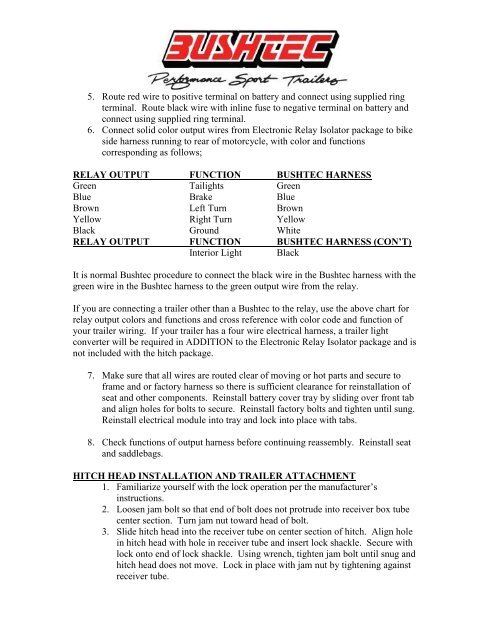
5. Route red wire to positive terminal on battery and connect using supplied ring<br />
terminal. Route black wire with inline fuse to negative terminal on battery and<br />
connect using supplied ring terminal.<br />
6. Connect solid color output wires from Electronic Relay Isolator package to bike<br />
side harness running to rear of motorcycle, with color and functions<br />
corresponding as follows;<br />
RELAY OUTPUT FUNCTION BUSHTEC HARNESS<br />
Green Tailights Green<br />
Blue Brake Blue<br />
Brown Left Turn Brown<br />
Yellow Right Turn Yellow<br />
Black Ground White<br />
RELAY OUTPUT FUNCTION BUSHTEC HARNESS (CON’T)<br />
Interior Light Black<br />
It is normal <strong>Bushtec</strong> procedure to connect the black wire in the <strong>Bushtec</strong> harness with the<br />
green wire in the <strong>Bushtec</strong> harness to the green output wire from the relay.<br />
If you are connecting a trailer other than a <strong>Bushtec</strong> to the relay, use the above chart for<br />
relay output colors and functions and cross reference with color code and function of<br />
your trailer wiring. If your trailer has a four wire electrical harness, a trailer light<br />
converter will be required in ADDITION to the Electronic Relay Isolator package and is<br />
not included with the hitch package.<br />
7. Make sure that all wires are routed clear of moving or hot parts and secure to<br />
frame and or factory harness so there is sufficient clearance for reinstallation of<br />
seat and other components. Reinstall battery cover tray by sliding over front tab<br />
and align holes for bolts to secure. Reinstall factory bolts and tighten until sung.<br />
Reinstall electrical module into tray and lock into place with tabs.<br />
8. Check functions of output harness before continuing reassembly. Reinstall seat<br />
and saddlebags.<br />
HITCH HEAD INSTALLATION AND TRAILER ATTACHMENT<br />
1. Familiarize yourself with the lock operation per the manufacturer’s<br />
instructions.<br />
2. Loosen jam bolt so that end of bolt does not protrude into receiver box tube<br />
center section. Turn jam nut toward head of bolt.<br />
3. Slide hitch head into the receiver tube on center section of hitch. Align hole<br />
in hitch head with hole in receiver tube and insert lock shackle. Secure with<br />
lock onto end of lock shackle. Using wrench, tighten jam bolt until snug and<br />
hitch head does not move. Lock in place with jam nut by tightening against<br />
receiver tube.